Table of Contents
Advertisement
Quick Links
Advertisement
Table of Contents

Related Manuals for Renishaw TS20


Summary of Contents for Renishaw TS20
- Page 1 Installation guide TS20 probe system www.renishaw.com/ts20 #renishaw...
- Page 2 Compliance information for this product is available by scanning the QR code or visiting www.renishaw.com/mtpdoc...
-
Page 3: Table Of Contents
TS20 probe with straight stylus . . . . . . . . . . . . . . . . . . . . . . . . . . . . . . . . . . . . . . . . . . . . . . . . . . . .3-2 TS20 probe with cranked stylus for applications where the straight stylus is not suitable . . . . . . . .3-3 Overtravel . - Page 4 This page is intentionally left blank . TS20 probe system...
-
Page 5: Before You Begin
Renishaw office. Renishaw warrants its equipment and software for a limited period (as set out in the Standard Terms and Conditions), provided that they are installed and used exactly as defined in associated Renishaw documentation. -
Page 6: Safety
. Information to the equipment installer All Renishaw equipment is designed to comply with the relevant UK, EU and FCC regulatory requirements. It is the responsibility of the equipment installer to ensure that the following guidelines are adhered to, in order for the product to function in accordance with these regulations: •... -
Page 7: Ts20 Basics
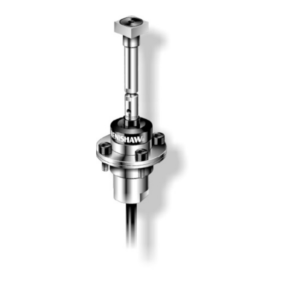
Automatic arm Introduction The TS20 is a 2D touch-trigger probe which can be used for tool setting applications on CNC lathes . During a tool setting rountine, each turret mounted tool is driven against the square tip stylus . When contact is made, a trigger signal is generated and tool offsets are automatically recorded in the machine control registers . -
Page 8: Ts20 Mounted On An Automatic Arm With Mi 8-4, Hsi, Or Hsi-C Interface
TS20 mounted on an automatic arm with MI 8-4, HSI, or HSI-C interface MI 8 interface An inhibit input enables an optical transmission type inspection probe and interface to be used on the same machine input as the TS20 . -
Page 9: System Installation
Ensure the probe cable is routed away from other cables carrying high currents . Probe false trigger The TS20-SCM should be installed on machines with a stable power supply i .e . Interference free . If false triggers occur, investigate the power supply rails for interference . -
Page 10: Specification
Specification TS20 probe with straight stylus Sense directions Normally ±X and ±Z axes of a lathe Uni-directional repeatability. 2 μm (0.00008 in) Valid for test velocity of 480 mm/min Maximum mean 2 sigma (2σ) value (1 .57 ft/min) at stylus tip... -
Page 11: Ts20 Probe With Cranked Stylus For Applications Where The Straight Stylus Is Not Suitable
TS20 probe with cranked stylus for applications where the straight stylus is not suitable 0 .02 mm (0 .0008 in) in Z direction 0 .03 mm (0 .0012 in) in X direction Non probing direction 39 mm (1.53 in) 34 mm (1.34 in) σ... -
Page 12: Overtravel
3.0 mm (0.12 in) 1.2 mm (0.05 in) 2.3 mm (0.09 in) TS20 probe with signal conditioning module ‘O’ ring supplied may be fitted in groove to seal probe mounting. Recommended ‘O’ ring dimensions Ø1 × 18,1 ID (Ø0 .039 × 0 .71 ID) (0 .12) 1 .6 (0 .063) -
Page 13: Stylus Fitting Instructions
NOTE: Break stem - please quote the part number when ordering a replacement stem . Break stem Break stem Break stem Application Application Application part number part number part number 25 mm (tooling) M-2008-0333 32 mm (tooling) M-2008-0604 40 mm (tooling) M-2008-0605 www.renishaw.com/ts20... -
Page 14: Stylus Alignment In X And Z Axes
. When alignment is achieved, tighten the clamping screws . Signal conditioning module 2950 (116) 32 (1 .26) 47 (1 .85) 32 (1 .26) Ø15 (0 .59) MINIMUM clearance Ø8 (Ø0 .32) TS20 probe system: System installation... -
Page 15: Ts20 Probe With Signal Conditioning Module
19 .3 (0 .76) (11 .6) Electrical specification TS20 with signal conditioning module (SCM) The TS20 probe is designed to be used wIth a load resistor. Minimum load resistor at 30 V 1K2 Ohms Maximum supply voltage 30 V Maximum current 25 mA - probe seated Minimum supply voltage 9 V... -
Page 16: Electrical Characteristics At 20° C (68° F)
B - Resistance in negative lead Probe Minimum Typical Maximum Minimum Typical Maximum Output voltage (Vo) 3.9 V 20.1 V 20.5 V (probe seated) Output voltage (Vo) 21.7 V 22.5 V 1.5 V 2.3 V (probe deflected) TS20 probe system: System installation... -
Page 17: Parts List
A-6527-1000 HSI-C probe system interface, support card and packaging . STYLI for TS20 . For more information, see “Stylus fitting instructions” on page 3-5 . 25 mm (tooling) A-2008-0601 Straight stylus with square tip stylus 10 x 10 mm (0 .39 x 0 .39 in) . - Page 18 UK@renishaw.com © 2002–2022 Renishaw plc . All rights reserved . This document may not be copied or reproduced in whole or in part, or transferred to any other media or language by any means, without the prior written permission of Renishaw .
Need help?
Do you have a question about the TS20 and is the answer not in the manual?
Questions and answers