Advertisement
Table of Contents
- 1 Using the PXI-8150B in a PXI-1020 Chassis
- 2 Step 1. Switch Mouse Routing for Internal Connection
- 3 Step 2A. Create a Boot Disk
- 4 Step 2B. Copy BIOS Update Files to Boot Disk
- 5 Step 2D. Set the Controller BIOS to Enable the LCD Signals
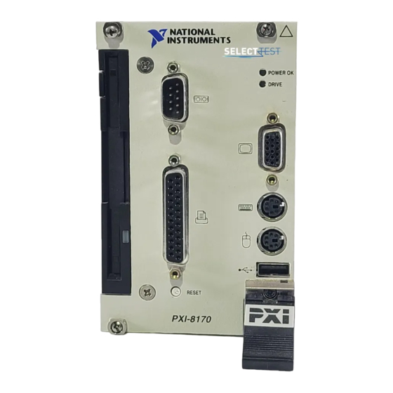
- 6 Using the PXI-8170 Series in a PXI-1020 Chassis
- 7 Step 2. BIOS Setup for LCD Support
- Download this manual
NOTE TO USERS
U
SING THE
S
C
ERIES
ONTROLLERS IN THE
Using the PXI-8150B in a PXI-1020 Chassis
Note
Before getting started, you must have an external VGA monitor. If your PXI
controller came with Windows NT, you must have access to a PC with Windows 98/95
installed to create a boot disk.
Step 1. Switch Mouse Routing for Internal Connection
National Instruments™, ni.com™ and PXI™ are trademarks of National Instruments Corporation. Product and company names mentioned herein are
trademarks or trade names of their respective companies.
322616B-01
© Copyright 1999, 2000 National Instruments Corp. All rights reserved.
PXI -8150B
™
This document describes how to set up your PXI-8150B or PXI-8170 series
controller card in a PXI-1020 chassis.
Slide switch S2 away from the controller front panel as shown below.
S2
Figure 1. Switch Used for PXI-1020 Setup on a PXI-8150B Series CPU Board
PXI-8170
AND
PXI-1020 C
HASSIS
February 2000
Advertisement
Table of Contents

Related Manuals for National Instruments PXI-8150B Series


Summary of Contents for National Instruments PXI-8150B Series
- Page 1 Slide switch S2 away from the controller front panel as shown below. Figure 1. Switch Used for PXI-1020 Setup on a PXI-8150B Series CPU Board National Instruments™, ni.com™ and PXI™ are trademarks of National Instruments Corporation. Product and company names mentioned herein are trademarks or trade names of their respective companies.
- Page 2 Step 2. Update the Controller BIOS to Route the Video Signals to the LCD Display This step involves four substeps: creating a boot disk, copying the BIOS update files to your newly created boot disk, setting the controller boot sequence to boot from the floppy drive, and setting the BIOS to enable the LCD signals.
- Page 3 640 × 480 resolution. Shut down Windows and power off your PXI-1020 chassis. Remove the VGA cable from the PXI controller. Reboot the system and verify that your LCD is working. © National Instruments Corporation Using the PXI-8150B/8170 Series in a PXI-1020 Chassis...
- Page 4 Using the PXI-8170 Series in a PXI-1020 Chassis Step 1. Set the LCD Display Resolution, Keyboard Routing, and Mouse Routing As shown in Figure 2, set the following switches: Set switch S1 to set the keyboard for front panel connection. Set switch S2 to set the mouse routing for internal connection.
- Page 5 CRT is enabled. If a CRT is not connected at boot, only the LCD is enabled. Note During the initial boot process, both the LCD and CRT displays are enabled. © National Instruments Corporation Using the PXI-8150B/8170 Series in a PXI-1020 Chassis...
Need help?
Do you have a question about the PXI-8150B Series and is the answer not in the manual?
Questions and answers