
Related Manuals for TPS Tenney TUJR

Summary of Contents for TPS Tenney TUJR
- Page 1 Operation and Maintenance Manual Tenney Junior Environmental Test Chambers Model TUJR Models TJR/TUJR Order Number: 113119 Revision Date: 01-25-15 Model TJR...
- Page 2 COPYRIGHT© 2014 THERMAL PRODUCT SOLUTIONS. ALL RIGHTS RESERVED REPRODUCTION OF THIS MANUAL IN ANY MEDIUM WITHOUT THE EXPRESS PERMISSION OF THERMAL PRODUCT SOLUTIONS IS PROHIBITED. LIMITED RIGHTS NOTICE TECHNICAL DOCUMENTATION/DATA This technical manual shall not, without the written permission of Thermal Product Solutions be either (a) used, released, disclosed, or reproduced in whole or in part or (b) used in whole or in part for manufacture except that (i) such release, disclosure or use is necessary for emergency repair or overhaul;...
-
Page 3: Table Of Contents
Table of Contents INTRODUCTION ............................1 ............................1 ONTACT NFORMATION ............................ 1 ARTS AND ERVICE NQUIRES ............................2 ECHNICAL PECIFICATIONS SAFETY ..............................3 ................................3 YMBOLS ................................4 ARNINGS SYSTEM OVERVIEW ............................ 6 ................................7 PPLICATION ....................... 7 NVIRONMENTAL ONDITIONING UNCTIONS ............................. - Page 4 ..........................21 OOST OOLING YSTEM ..............................21 PERATION TEMPGARD IV IV A ....................22 LARM AND HUTDOWN IRCUIT ........................23 NTRINSICALLY NTERIOR ESIGN ..............................23 VERVIEW ..........................23 NTRINSIC ESIGN EATURES ........................23 HEATHED ELECTRICAL HEATERS ......................24 EATER URFACE EMPERATURE ONTROL LV L...
- Page 5 OPERATION ............................. 40 ............................ 40 TANDARD ONTROL ANEL .......................... 41 TANDARD PERATION ROCEDURE IV IV I ......................42 PERATION WITH EMPGARD NSTALLED ............................42 PERATION ROCEDURE ............................... 43 LARMS IV IV A –WATLOW EZ ................... 44 EMPGARD LARM ETPOINT NTRY ........................
- Page 6 THIS PAGE INTENTIONALLY LEFT BLANK P a g e Table of Contents...
-
Page 7: 1.0 Introduction
1.0 Introduction Congratulations on purchasing a chamber from one of the fine divisions of Thermal Product Solutions. Your chamber has been designed to operate with the reliability you expect for the demands you impose on your product and research testing. We truly hope that every aspect of chamber design and quality will measure up to your strictest standards. -
Page 8: Technical Specifications
Technical Specifications This table shows the major mechanical, electrical and environmental specifications for this unit. Unit Type Model Numbers: Model TJR Tenney Junior - Benchtop Unit Model TU-JR Tenney Junior - Upright Unit Mechanical Shipping Weight: 260 lbs. 16" W x 11" D x 12" H = 1.22 Ft (406.4 W x 279.4 D x 304.8 H Internal Capacity: Millimeters) -
Page 9: 2.0 Safety
2.0 Safety It is important that you read and understand all Warning statements listed throughout the manual! Symbols Various symbols are used throughout the manual to alert the reader to a potentially dangerous situation. Indicates a potentially hazardous situation which, if not avoided, could result in death or serious injury. -
Page 10: Warnings
Warnings 1. Read this entire Operation Manual, as well as the vendor manuals and cut-sheets provided before operating this equipment! Failure to adhere to any Safety Warning, or failure to follow the proper operating procedures listed throughout any of the information provided, could cause damage to your equipment, personal injury, or death. - Page 11 15. Refrigerant under high pressure is used. Only qualified refrigeration mechanic personnel should ever be permitted to perform any service-related procedure on the refrigeration system. 16. Do not adjust any mechanical components such as refrigeration valves or any electrical components except as directed in this manual.
-
Page 12: 3.0 System Overview
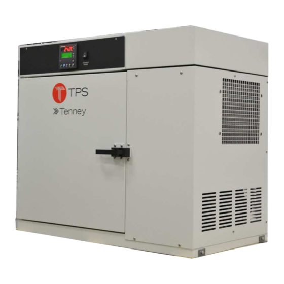
3.0 System Overview Control Panel Chamber Workspace Machinery Compartment Machinery Compartment Figure 1 Model TUJR Front View Control Panel Chamber Workspace Machinery Compartment Figure 2 Model TJR Front View P a g e Tenney Junior Test Chambers-Models TJR and TUJR... -
Page 13: Application
Application The Tenney Junior family of environmental test chambers are innovative reach-in types that provide a wide range of temperature conditioning with a set of diverse optional conditioning equipment. This manual applies to the following models in the Tenney Junior family which employ the Watlow F4 profiling type controller. Environmental Conditioning Functions •... -
Page 14: Heating-All Models
Heating-All Models Heating of the chamber is achieved with the use of open air low mass nichrome wire heating elements. These elements have low thermal lag and provide rapid response to the controller's demands. The elements are configured in a serpentine pattern within stainless steel racks and are supported with ceramic insulators. Heater racks are installed in the conditioning plenum. -
Page 15: Cooling-All Models
Cooling-All Models Cooling of the chamber is achieved by re-circulating chamber air through a refrigerated cooling coil in the chamber conditioning plenum. Non-CFC refrigerants are used. The chamber is equipped with a cascade refrigeration system that uses capillary tube type refrigerant metering to the cooling coils. - Page 16 Pressure Air-Cooled Switch PS1 Condenser High Stage Low Stage Compressor Compressor Figure 5 TJR Refrigerant System-Rear View P a g e Tenney Junior Test Chambers-Models TJR and TUJR...
-
Page 17: Capillary Tube Control Description
Capillary Tube Control Description This system employs capillary tube type refrigerant control. A long length of seamless copper tubing with a small internal diameter is used to feed the evaporator coil. The tube acts as an automatic throttle in controlling refrigerant pressure and flow to the evaporator. With the compressor running, a high pressure is maintained on the inlet to the capillary tube, and a low pressure is maintained in the evaporator. -
Page 18: High Pressure Cut-In Switch Ps1
High Pressure Cut-In Switch PS1 An Artificial Loading solenoid valve SV will be energized by the High Pressure Cut-in Switch PS1 when low stage compressor head pressures reaches 280 PSI. This action dumps refrigerant into the expansion tank for storage until the pressure drops to 220 PSI. Compressor Motor Overloads A motor overload protective device is installed in the windings of each compressor, which will open if the motor windings exceed a preset temperature. -
Page 19: Over Temperature Protection
Chamber air is conditioned in the ceiling plenum where the circulation fan, heater elements, and refrigeration coil are located. A propeller type fan driven by an externally mounted motor generates airflow. The plenum cover prevents direct heat radiation to the workspace. Process air is drawn up into the left side of the plenum. -
Page 20: Watlow F4 Temperature Controller
Watlow F4 Temperature Controller Features Temperature conditions may be controlled with the standard Watlow F4 Controller. The WF4 is a powerful ¼ DIN profiling type controller with the following features. Single Channel Profiling: Forty Profiles, 256 Steps Automatic & Manual Control 1 Input: Universal Type (RTD is Std.) 4 Digital Inputs 2 Auxiliary Analog Inputs - Optional... -
Page 21: Keys
Important! The configuration set-up is mainly provided for your reference. Not all of the parameters shown apply to your chamber. Changes to some of the set-up parameters may drastically affect your chamber performance and void your warranty. Contact the TPS Service Dept. before attempting any changes. P a g e... -
Page 22: 4.0 Options
4.0 Options There are several options that are available for this series that can be ordered as required. Boost Heat As an option, your chamber may be equipped with the boost heat feature, which includes extra heaters to provide rapid increases in temperature. As the main controller’s heat output energizes the main heater bank, it will also energize an internal On-Delay timer. - Page 23 Your chamber will require a compressed air supply for the Dry Air Purge System option. The system employs a twin tower heatless desiccant dryer that is mounted on the back side of the chamber. The compressed air supply should be clean and dry, and range from 80 PSIG min. to 100 PSIG max. The connection type is ¼” FPT.
-
Page 24: Gn 2 Purge System
Purge System Your chamber will require a supply of gaseous nitrogen for the GN2 Purge System option. The supply may range up to 100 PSIG maximum. The connection is type 1/8” NPT. Make sure the connection is secure. Reference the corresponding “Option” section in this manual and your chamber specifications for more details. -
Page 25: Ln 2 Boost Cooling System
Boost Cooling System The LN Boost Cooling System is provided to increase the rate or limit of cooling beyond the means of the refrigeration system. Boost cooling is achieved by injecting liquid nitrogen into the chamber through a header pipe in the conditioning section. LN has a boiling point of -196 degrees Celsius (-320 deg. - Page 26 Flow Adjustment Vent Valve LN2 Injection Supply Inlet Figure 13 LN Supply System P a g e Tenney Junior Test Chambers-Models TJR and TUJR...
-
Page 27: Co 2 Boost Cooling System
Boost Cooling System The CO Boost Cooling System option may be provided to increase the rate of cooling beyond the means of the refrigeration system. Boost cooling is achieved by injecting liquid carbon dioxide into the chamber through an orifice within an injection port. CO has a boiling point of -78.5 degrees Celsius (-109.3 deg. -
Page 28: Tempgard Iv Iv Alarm And Shutdown Circuit
TEMPGARD IV IV Alarm and Shutdown Circuit A comprehensive alarm and shutdown circuit may be provided for protection against product over/under temperature. This optional feature utilizes a Watlow EZ Zone Controller configured as a Tempgard IV IV temperature protector. The EZ Zone is a microprocessor based controller that incorporates programmable high and low temperature limits. -
Page 29: Intrinsically Safe Interior Design
Intrinsically Safe Interior Design Overview Intrinsically safe equipment has been incorporated into the chamber interior design to help protect the chamber from an explosive condition that could arise when processing with flammable volatiles or combustibles. Explosion relief equipment is included with this design. Please note that using the equipment below does not automatically classify your chamber as a Class A type chamber under NFPA 86. -
Page 30: Heater Surface Temperature Control
Your equipment configuration may be slightly different from what is shown. Older style heaters are larger in diameter. Heater Surface Temperature Control Surface temperature of each sheathed heater is monitored by two separate Watlow LV Limit Controllers to prevent auto ignition of combustible vapors / materials processed in the chamber. -
Page 31: Watlow Lv Limit Controller
Configuration #2: The second LV Limit Controller is used to remove power from Master Contactor 1CON and the conditioning control circuitry when a different – slightly higher limit setpoint is reached. These T/C Tube controllers are normally designated 1TS, 3TS, 5TS, Wire Entry T/C Tube etc. -
Page 32: Intrinsic Safety Barriers
Intrinsic Safety Barriers Signal wires from RTDs, thermocouples, or transducers are connected to intrinsic safety barriers in the control compartment. Intrinsically safe equipment is defined as “equipment and wiring which is incapable of releasing sufficient electrical or thermal energy under normal or abnormal conditions to cause ignition of a specific hazardous atmospheric mixture in its most easily ignited concentration.”... - Page 33 Door Safety Chain Brixon Door Latch Figure 21 Explosion Relief Features P a g e Tenney Junior Test Chambers-Models TJR and TUJR...
-
Page 34: Data And Communications Ports
Data and Communications Ports Three types of communication to external devices are offered as options. RS-485 Interface RS-485 is a multipoint communications standard set by the Electronics Industry Alliance (EIA) and Telecommunications Industry Association (TIA). RS-485 supports several connection types, including DB-9 and DB-37. -
Page 35: Linktenn32 Software
LinkTenn32 supports the following controllers: TPS - VersaTenn III, IV, and V, Blue M Pro550 / 750, Watlow 942 & F4, and Partlow MIC 1462 Controllers. The major features provided include: •... -
Page 36: 4.10 Chart Recorder
4.10 Chart Recorder As an option, your chamber may be provided with either a circular or strip type chart recorder to record temperature versus time. This recorder is typically a one-pen type, which also digitally displays the process value. A 100 ohm platinum RTD is used for temperature measurement. It is placed in the discharge air of the chamber plenum. -
Page 37: 5.0 Installation
5.0 Installation Follow the steps in this section to ensure a safe and accurate installation of your unit. Delivery and Uncrating of Unit Inspect equipment and shipping crate immediately upon receipt. If any damage is apparent, you should discuss it with the trucking delivery person and contact the transportation company immediately. Make notes of any damage on the Bill Of Lading. -
Page 38: Air Supply Connection
• Do not position the chamber in a manner that would make it difficult to operate your main power disconnect switch. See “Power Connection” below. • Make sure the chamber is leveled when set up. Very Important! Upon completion of the initial installation of the chamber and upon completion of any maintenance procedure, make sure that all access panels that have been removed are reinstalled securely before operating the unit. -
Page 39: Gn 2 Connection
Connection Your chamber will require a supply of gaseous nitrogen for the GN Purge System option. The GN supply may range up to 100 PSIG maximum. The connection is type 1/8” FPT. Make sure the connection is secure. Reference the corresponding “Option” section in this manual for a detailed operation description. Gaseous nitrogen displaces oxygen. -
Page 40: Ln 2 Connection
Connection Your chamber will require a supply of liquid nitrogen for the LN2 Boost Cooling option. The supply may range up to 40 PSIG maximum. The connection is type 1/8” NPT. Make sure the connection is secure. Reference the corresponding “Option” section in this manual and your chamber specifications for more details. A Strato-flo check valve is mounted on the side of the chamber to insure that the chamber does not become pressurized. -
Page 41: Ln 2 Flow Adjustment
Flow Adjustment LN2 systems are provided with a manually set flow adjusting valve, which permits the adjustment of Solenoid nitrogen flow to avoid incomplete evaporation at Valve LN2SOL varying LN2 supply pressures. As the chamber cools to the extreme cold temperature limit, Flow complete evaporation of liquid nitrogen may not Adjustment... -
Page 42: Co 2 Connection
Connection Your chamber will require a supply of liquid carbon dioxide for the CO Boost Cooling option. The supply may range up to 1000 PSIG. The connection is type 1/4” 90° Flare. Make sure the connection is secure. Reference the corresponding “Option” section in this manual for a detailed operation description. Carbon Dioxide gas displaces oxygen. -
Page 43: Power Supply Specifications And Connection
Otherwise, erratic operation and damage may occur to your equipment, which may void your warranty. If you have any questions, please call the TPS Service Department. One of the most common causes of equipment malfunction is low line voltage as the power source to the unit. -
Page 44: Making The Power Supply Connection To The Chamber
- 60 HERTZ SUPPLIES - - 50 HERTZ SUPPLIES - LINE VOLTAGE MIN. / MAX. TABLE LINE VOLTAGE MIN. / MAX. TABLE Chamber Minimum Maximum Chamber Minimum Maximum Voltage Voltage Voltage Voltage Voltage Voltage Rating Rating Operation outside these 50 Hz limits can result in damage Supply Operation outside these... -
Page 45: Application Of Power
Figure 28 TJR Power Cable and Plug Application of Power • Before energizing any equipment, make a visual inspection for loose components, electrical connections, fittings, etc. Shut all operating switches to the “OFF” position before energizing. • Have trained personnel start and check out the equipment before its first cycle. P a g e Tenney Junior Test Chambers-Models TJR and TUJR... -
Page 46: 6.0 Operation
6.0 Operation Standard Control Panel The Control panel is used to control all operator functions of the chamber. • Power ON/OFF Switch-Controls power to the chamber. The integral green light is on when power is on to the chamber. • Chamber ON/OFF Light Switch (optional) - Turns the light on or off in the chamber. -
Page 47: Standard Operationp
Standard Operation Procedure Do not open chamber doors until chamber temperature drops below 200° F (93° C) when applicable. Human exposure to temperature extremes can cause injury. Take appropriate precautions when handling product. Do not open chamber door after operating at extreme low temperatures. Human exposure to temperature extremes can cause injury. -
Page 48: Operation With Tempgard
Operation with Tempgard IV IV Installed Figure 30 Tempgard IV Controller Audible Buzzer Activates when the alarm setpoint is exceeded. Watlow EZ Zone Used to program high or low limit temperature setpoints. This button is pressed to reset an alarm activation. See 6.4.1 for a detailed RESET description. -
Page 49: Alarms
Important: Check to see if any features or optional equipment must be turned on with an Event Output from the main controller. If an Event Output were supplied, a Controller Event Output Label with the Event Output listing would be installed on the side of the chamber. Event Outputs are described either in one of the various “Option”... -
Page 50: Tempgard Iv Iv Alarm
Tempgard IV IV Alarm Setpoint Entry–WATLOW EZ The purpose of this section is to explain how to set your low & high temperature alarm setpoints with the optional Watlow EZ Zone Tempgard IV IV. This feature is normally used for product over / under temperature protection and can be changed for each process cycle desired. -
Page 51: Saving Andr
Saving and Restoring User Settings (Copied from the Watlow Limit Controller Manual) Recording setup and operations parameter settings for future reference is very important. If you unintentionally change these, you will need to program the correct settings back into the controller to return the equipment to operational condition. - Page 52 Periodic Maintenance Tasks Period Assembly Task drive up compressor head pressure, causing it to trip out. If necessary, clean with a brush or vacuum cleaner. Frequency of cleaning depends upon the air quality at the chamber. The condenser fan should also be checked for cleanliness. Make sure the fan spins freely.
-
Page 53: Preventative Maintenance
Preventative Maintenance Schedule / Log For each of the items to be inspected, refer to item description sections for details on maintenance and service. PREVENTATIVE MAINTENANCE SCHEDULE / LOG Inspection Period Actual Date Actual Date Actual Date Actual Date ITEM TO BE Inspected / Inspected / Inspected /... -
Page 54: 8.0 Troubleshooting
The information here should also help you in localizing trouble so that you can better describe the malfunction when contacting the TPS Service Department. Refer to the appropriate electrical and refrigeration drawings when using these troubleshooting suggestions. - Page 55 Starting capacitor is defective Replace Internal compressor problem Measure winding resistance, test for grounds, contact TPS Service 7. Repeated shorting or blowing Excessive start time, voltage too low Correct low line voltage problem of start capacitors 8. Compressor starts, hums, runs...
- Page 56 Noisy compressors Compressor loose on mounts Tighten hold down nuts. 15. Noisy compressors, even Broken springs within compressor Replace compressor - Call TPS with secure hold-downs housing for assistance P a g e Tenney Junior Test Chambers-Models TJR and TUJR...
-
Page 57: 9.0 Maintenance And Servicing
9.0 Maintenance and Servicing Refrigeration System The refrigeration system is permanently sealed and a periodic oil change is NOT required. If a loss of cooling performance is noted, immediately check the condenser for restricted air flow. All motors are permanently lubricated; therefore, greasing or oiling is not required. Introduction Only qualified service personnel should ever be permitted to perform any service related procedure on this chamber! - Page 58 9.1.3.1 High Stage The high stage is a conventional single-stage system having a compressor, air or water cooled condenser, expansion valve, and evaporator. The evaporator is the cascade condenser, serving the low stage. Modern systems use R404a in the high stage, making -50 deg. F refrigerant temperature possible at 0 PSIG suction pressure.
-
Page 59: Load Limits
Load Limit Switch 9.1.3.8 A high pressure cut-in sensor monitors the pressure inside the low stage compressor and will activate the Load Limit Switch 4PS when the low stage discharge pressure reaches 280 PSIG. This will energize the Artificial Loading solenoid 14SOL. 4PS will be deactivated when the pressure falls to 240 PSIG. 9.1.3.9 Artificial Loading In response to the Thermostat switch TS or the Load Limit switch 4PS, the Artificial Loading solenoid will... -
Page 60: Evacuation
Evacuation Refrigerants R23 and R404a are expensive and there are times when charges must be recovered. A contaminated system must be cleaned and evacuated regardless of refrigerant expense. If there is a possibility that moisture, non-condensable materials, or the wrong refrigerant contaminated a system, recover the charge and evacuate. -
Page 61: Spare Parts
Spare Parts Spare parts are available for the small water supply level reservoir from the TPS Service Department. However, there are no internal spare parts available for the main generator housing. The entire generator housing would need to be replaced if it is found to be defective. -
Page 62: 10.0 Drawings And Oem Manuals
10.0 Drawings and OEM Manuals Drawing Name Drawing # Electrical Schematic – Special Chambers, e.g., Model TJR-INS D800 Electrical Schematic w/ WF4 (Standard Chambers) E - 3362 - 4 Electrical Schematic w/ WF4 (CE Marked Chambers Only) E - 3417 - 4 Refrigeration Schematic (Standard Chambers) R - 1851 - 4 Refrigeration Schematic (CE Marked Chambers Only)
Need help?
Do you have a question about the Tenney TUJR and is the answer not in the manual?
Questions and answers