Table of Contents
Advertisement
Quick Links
UM3097
User manual
Source measurement unit (SMU) and debugger/programmer for
STM32 microcontrollers
Introduction
STLINK-V3PWR
is a two-in-one standalone debugger probe and a source measurement unit (SMU) designed to synchronize
code execution with a power consumption of STM32 applications in real time. This tool is specifically adapted for power
consumption optimization (patent pending).
STLINK-V3PWR can be used as a standalone source measurement unit to supply power and measure the current consumption
of the target application. The product keeps the output voltage constant during fast current transient from very low current to
high current.
STLINK-V3PWR is also a standalone debugging and programming probe for STM32 microcontrollers. The product embeds a
multi-path bridge interface with an integrated level shifter to adapt to the target application I/Os voltage.
®
STLINK-V3PWR USB Type-C
connector allows data communication with the host PC and sinks up to 5 V/3 A to supply both
the probe and the target application, via the SMU and the auxiliary output.
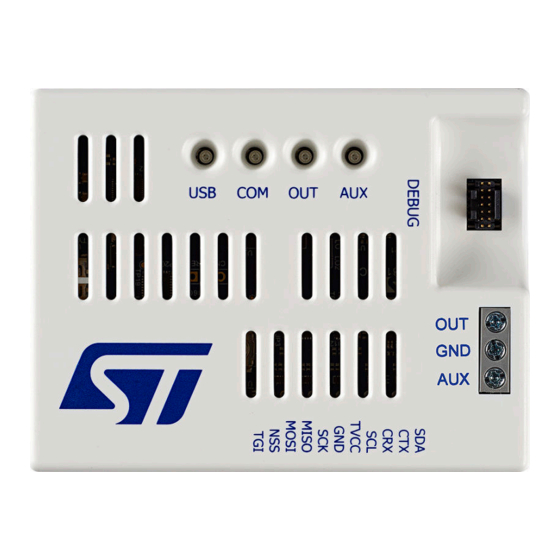
Figure 1.
STLINK-V3PWR top, bottom, and cable views
Picture is not contractual.
UM3097 - Rev 1 - March 2023
www.st.com
For further information contact your local STMicroelectronics sales office.
Advertisement
Table of Contents

Related Manuals for ST STLINK-V3PWR


Summary of Contents for ST STLINK-V3PWR
-
Page 1: Figure 1. Stlink-V3Pwr Top, Bottom, And Cable Views
(patent pending). STLINK-V3PWR can be used as a standalone source measurement unit to supply power and measure the current consumption of the target application. The product keeps the output voltage constant during fast current transient from very low current to high current. -
Page 2: Features
UM3097 Features Features • 1‑Quadrant source measurement unit with high resolution, and measurement flexibility: – Programmable voltage source from 1.6 to 3.6 V – Output current rating 500 mA with overcurrent protection (OCP) at 550 mA – Programmable sampling rate from 1 SPS to 100 kSPS –... -
Page 3: Ordering Information
UM3097 Ordering information Ordering information To order the STLINK-V3PWR SMU and in-circuit debugger/programmer for STM32, refer to Table Table 1. Ordering information Order code Reference Description Debug board for STM32 microcontrollers including STLINK-V3PWR STLINK-V3PWR simultaneous current measurement UM3097 - Rev 1... -
Page 4: Development Environment
The driver installation is not mandatory since Windows 10 but allocates an ST‑specific name to the ST-LINK COM port in the system device manager. For details information regarding the ST-LINK USB driver, refer to the technical note Overview of ST-LINK derivatives (TN1235). -
Page 5: Glossary
UM3097 Glossary Glossary Table 3. Glossary Term Meaning Auxiliary output voltage Target application Target product application embedding an STM32 MCU with peripherals Ground Over current protection Main output voltage Over voltage protection SMPS Switched‑mode power supply Source measure unit UM3097 - Rev 1 page 5/30... -
Page 6: Product Information
“JTAG 20 Pin 2.54 mm to 10 Pin 1.27 mm adapter”) STLINK-V3PWR connectors and LEDs identification This section aims to identify the location of the STLINK-V3PWR connectors and LEDs. They are illustrated with the silkscreen on the casing serving as a functional reference for most connectors. A connection overview is given here: ®... -
Page 7: Usb Connection With A Host Pc
5.3.2 Detailed description For the data interface, the STLINK-V3PWR’s USB-C must be connected to a USB HS host port. USB FS (full speed) or USB LS (low speed) modes are not supported. Connecting STLINK-V3PWR to a USB SS (super speed) host port is also possible as the USB SS port runs in HS mode. -
Page 8: Mechanical Information
OUT and AUX disabled and the USB LED lights in orange color. Note: Connection to a USB charger is not a functional use case for STLINK-V3PWR. In that case, USB LED lights in green color (valid power source) and COM LED blinks red color (waiting for USB enumeration). Refer to Section 7.6 LEDs... -
Page 9: Quick Start
Quick start This section describes how to start with STLINK-V3PWR to make power measurements: Check that the bundle is complete (STLINK-V3PWR with three flat cables and a bundle of four wire jumpers). Install or update the power measurement software (for example STM32CubeMonitor-Power). -
Page 10: Software Configuration
Software configuration Launch the STM32CubeMonitor-Power application. Select the COM port of the device. Figure 5. STM32CubeMonitor-Power setting Click on the "TAKE CONTROL" button to handle the STLINK-V3PWR probe. – ACQUISITION & REPLAY: – Set "Sampling Frequency" to 20000 Hz [recommended value] –... -
Page 11: Stlink-V3Pwr Functional Description
Level shifter Bridge SMU output (OUT) The STLINK-V3PWR’s SMU output is accessible on the POWER’s 3‑pin screw connector between the OUT pin (positive node) and GND pin (negative node). Figure 7 provides a block diagram of the SMU. Figure 7. -
Page 12: Voltage Source
UM3097 SMU output (OUT) The STLINK-V3PWR’s SMU operates as a 1‑quadrant voltage source and current meter. The SMU operating area is illustrated in Figure Figure 8. STLINK-V3PWR SMU operating area short-circuit overcurrent +500 mA operating measurement area +1.6 V +3.6 V 7.2.1... -
Page 13: Self-Calibration Management
Sampling rate selection does not impact the current measurement DC accuracy. 7.2.3 Self‑calibration management STLINK-V3PWR has built‑in self‑calibration circuitry to compensate for the current measurements offset due to temperature variation. A self-calibration is automatically performed during current measurements acquisition every +/- 5°C temperature change inside STLINK-V3PWR. -
Page 14: Auxiliary Power Source Output (Aux)
13). Warning: As STLINK-V3PWR is supplied from a host PC USB port, the host PC USB port should be able to support the equivalent amount of power consumed on the AUX output. Else, the host PC USB port OCP might trigger; making STLINK-V3PWR turn OFF. Accordingly, it is ®... -
Page 15: Target Voltage Connection (T_Vcc)
On the BRIDGE connector, the functionality is available with or without hardware flow control (CTS/RTS). On the BRIDGE connector TXD signal is the Rx for the target (Tx for STLINK-V3PWR), the RXD signal is the Tx for the target (Rx for STLINK-V3PWR), the CTS signal is the RTS for the target (CTS for STLINK-V3PWR) and the RTS signal is the CTS for the target (RTS for STLINK-V3PWR). -
Page 16: Bridge Functions
I/O software configuration through the public ST bridge software interface. LEDs management STLINK-V3PWR has four bi‑color LEDs which allow the user to know the status of the product at any time. The assigned function of each LED is noticed on the housing. -
Page 17: Table 7. Com Led
Orange The last communication with the target has failed STLINK-V3PWR is in the idle state (the USB enumeration with the PC is finished and the STLINK-V3PWR is waiting for an application to connect). The first enumeration with the PC is taking place. If an STLinkUpgrade application is running, Blinking red the firmware is being programmed. -
Page 18: Electrical And Performance Parameters
Electrical and performance parameters In this section, all parameters are not guaranteed: They are extracted from the design phase and the product validation on a few STLINK-V3PWR samples. They are not issued from characterization or a calibration process. Absolute maximum rating Table 10. -
Page 19: Aux Output (Aux) Voltage Source Characteristics
UM3097 AUX output (AUX) voltage source characteristics Symbol Parameter Conditions Min. Typ. Max. Unit Overcurrent 1.6 V < V < 3.6 V protection threshold Short circuit = 3.6 V protection = 1.6 V threshold OCP blanking 1.6 V < V <... -
Page 20: Debug And Bridge Performance
Debug and bridge performance Table 14 gives an overview of the achievable maximal performances with STLINK-V3PWR on different communication channels. Those performances are also depending on the overall system context (target included), so they are not guaranteed to be always reachable. For instance, a noisy environment or connection quality can impact system performance. -
Page 21: Board Connectors Description
Type Definition Signal is an input for STLINK-V3PWR and an output for the target application Signal is an output for STLINK-V3PWR and an input for the target application Bidirectional signal or can be configured as input or output (default input) -
Page 22: Bridge (I 2 C, Can, Spi, Uart, And Gpio)
2. Input reference voltage for debug interface level shifters (must be connected into target application onto VDDIO domain) 3. T_SWO: SWO is optional, and required only for Serial Wire Viewer (SWV) trace. 4. Tied to GND by the STLINK-V3PWR firmware after its initialization. Might be used by the target for the detection of the tool. Note:... -
Page 23: Flat Ribbons
3. Optional loopback of T_JCLK on the target application side. Not connected on the STLINK-V3PWR side. 4. NC means not connected. 5. Tied to GND by the STLINK-V3PWR firmware after its initialization. Might be used by the target application to detect the STLINK-V3PWR connection or might be connected to GND. -
Page 24: Federal Communications Commission (Fcc) And Ised Canada Compliance
UM3097 Federal Communications Commission (FCC) and ISED Canada Compliance Statements Federal Communications Commission (FCC) and ISED Canada Compliance Statements 11.1 FCC Compliance Statement Part 15.19 This device complies with Part 15 of the FCC Rules. Operation is subject to the following two conditions: (1) this device may not cause harmful interference, and (2) this device must accept any interference received, including interference that may cause undesired operation. -
Page 25: Revision History
UM3097 Revision history Table 21. Document revision history Date Revision Changes 16-Mar-2023 Initial release. UM3097 - Rev 1 page 25/30... -
Page 26: Table Of Contents
Product content ..............6 STLINK-V3PWR connectors and LEDs identification ....... . . 6 USB connection with a host PC. - Page 27 UM3097 Contents 7.4.5 Baud rate computing ........... . . 15 Bridge functions.
-
Page 28: List Of Tables
UM3097 List of tables List of tables Table 1. Ordering information..............3 Table 2. -
Page 29: List Of Figures
STLINK-V3PWR top, bottom, and cable views ........ - Page 30 ST’s terms and conditions of sale in place at the time of order acknowledgment. Purchasers are solely responsible for the choice, selection, and use of ST products and ST assumes no liability for application assistance or the design of purchasers’...
Need help?
Do you have a question about the STLINK-V3PWR and is the answer not in the manual?
Questions and answers