
Related Manuals for ABB SCC-E


Summary of Contents for ABB SCC-E
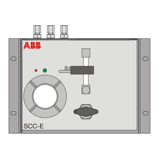
- Page 1 Analyze Continuous Gas Analyzers – Sample Conditioning SCC-E Sample Gas Feed Unit Operator’s Manual 42/23 58 EN Rev. 1 SCC-E...
-
Page 2: Table Of Contents
Checking the Gas Paths for Leaks Troubleshooting Chapter 5 Shutting Down and Packing the Feed Unit Shutting Down the Feed Unit Packing the Feed Unit Appendix Description Circuit Diagrams SCC-E Sample Gas Feed Unit Operator’s Manual 42/23-58 EN Rev. 1... -
Page 3: Preface
This operator’s manual contains all the information you need to install, commission, Operator’s Manual operate and maintain the SCC-E sample gas feed unit safely and in accordance with the regulations. This operator’s manual contains information on all the function units of the sample gas feed unit. -
Page 4: General Safety Information
Additional If the information in this manual does not cover a particular situation, ABB Service Information is prepared to supply additional information as needed. -
Page 5: Safety Tips For Handling Electronic Measurement Devices
The possibility of safe operation is excluded: • If the unit is visibly damaged • If the unit is no longer operational • After prolonged storage under adverse conditions • After severe transport stresses. 42/23-58 EN Rev. 1 SCC-E Sample Gas Feed Unit Operator’s Manual... -
Page 6: Preparing The Installation
Preparing the Installation Normal Operation Normal Operation The SCC-E sample gas feed unit is designed for continuous dosed sample gas feeding. The SCC-E sample gas feed unit with Peltier cooler is additionally designed for cooling the sample gas and separating and removing the condensate. -
Page 7: Power Supply
Quantity Description SCC-E Sample Gas Feed Unit Operator’s Manuals (1 copy in German, 1 in English) Diaphragm Pump Spare Parts Set The mounting brackets are fitted in the factory. 42/23-58 EN Rev. 1 SCC-E Sample Gas Feed Unit Operator’s Manual... -
Page 8: Dimensional Drawing
• The mounting brackets are fitted in the factory, with about 2.5 cm projection to the rear wall. • Slope max. 5°. SCC-E Sample Gas Feed Unit Operator’s Manual 42/23-58 EN Rev. 1... -
Page 9: Sample Gas Feed Unit Installation
Unscrew the mounting brackets from the rear of the side panels. If necessary, exchange the fittings flange on the case cover with the blank flange on the rear wall. Take care not to bend or squash any hoses. 42/23-58 EN Rev. 1 SCC-E Sample Gas Feed Unit Operator’s Manual... -
Page 10: Connecting The Sample Gas Pipes
The gas connections are PPH screw connections for DN 4/6 mm hose. Connect Gas Pipes Connect the gas pipes to the gas inlets and outlet. The gas pipes should be made from material that is suited to the measuring task. SCC-E Sample Gas Feed Unit Operator’s Manual 42/23-58 EN Rev. 1... -
Page 11: Connecting The Electrical Cables
Connect the power supply leads to the power supply. The sample gas feed unit may start when the power supply is connected. 42/23-58 EN Rev. 1 SCC-E Sample Gas Feed Unit Operator’s Manual... -
Page 12: Sample Gas Feed Unit Start-Up
“Pump” push-button is pressed (lights up green). The sample gas may be switched on. Set the sample gas flow using the needle valve (max. 70 l/h). SCC-E Sample Gas Feed Unit Operator’s Manual 42/23-58 EN Rev. 1... -
Page 13: Sample Gas Pump Control
< 2,5 °C Lights up yellow too low < 0 °C Off (status alarm + pump off) See section “Troubleshooting” for further information on cooler problems (see page 22). 42/23-58 EN Rev. 1 SCC-E Sample Gas Feed Unit Operator’s Manual... -
Page 14: Maintenance
Start the feed unit again: Switch on power supply to feed unit. The sample gas flow should only be restarted after the lead time period. Continued on next page SCC-E Sample Gas Feed Unit Operator’s Manual 42/23-58 EN Rev. 1... - Page 15 Replacing the Condensate Pump Hose, continued Fig. 4 Condensate Pump, Hose and Pump Head with Roller Mounting 1 Moving belt 3 Hose 5 Pressure rollers 2 S-clip 4 Hose connections 6 Dovetail guides 42/23-58 EN Rev. 1 SCC-E Sample Gas Feed Unit Operator’s Manual...
-
Page 16: Replacing The Condensate Pump Pressure Rollers And Springs
Start the feed unit again: Switch on power supply to feed unit. The sample gas flow should only be restarted after the lead time period. Continued on next page SCC-E Sample Gas Feed Unit Operator’s Manual 42/23-58 EN Rev. 1... - Page 17 5 Roller Mounting 2 S-clip 6 Pressure Springs (x 4) 3 Nuts for Securing the Pump Head (x 2) 7 Roller Axle 4 Pump Head 8 Pressure Roller (x 2) 42/23-58 EN Rev. 1 SCC-E Sample Gas Feed Unit Operator’s Manual...
-
Page 18: Replacing The Diaphragm And Valve Plates In The Diaphragm Pump
Mark both pump hoses: The pump inlet hose is connected to the diaphragm filter outlet and the pump outlet hose is con- nected to the flow meter inlet. Continued on next page SCC-E Sample Gas Feed Unit Operator’s Manual 42/23-58 EN Rev. 1... - Page 19 Check all the parts for dirt and, if necessary, clean them with a dry cloth or compressed air. Do not use solvents for cleaning as they can attack the plastic parts. Continued on next page 42/23-58 EN Rev. 1 SCC-E Sample Gas Feed Unit Operator’s Manual...
- Page 20 Check that the gas feed paths have no leaks (see instructions on p. 21). Switch on power supply to feed unit. The sample gas flow should only be restarted after the lead time period. SCC-E Sample Gas Feed Unit Operator’s Manual 42/23-58 EN Rev. 1...
-
Page 21: Checking The Gas Paths For Leaks
Using a U-pipe manometer, for example (pipe diameter 7 to 8 mm), check the drop in pressure; this must not exceed 0.1 mbar per minute. Similarly, check for leaks from the other side. 42/23-58 EN Rev. 1 SCC-E Sample Gas Feed Unit Operator’s Manual... -
Page 22: Troubleshooting
Check Peltier element voltage at terminals X2-3 and indication = room defective X2-4 (see circuit diagram on page 26): Voltage > 13 VDC ⇒ transistor defective; replace transistor T1. temperature, LED K1 lights up constantly SCC-E Sample Gas Feed Unit Operator’s Manual 42/23-58 EN Rev. 1... -
Page 23: Shutting Down And Packing The Feed Unit
The amount of drying agent used should be adequate for the package volume and the planned shipping time (at least 3 months). The box should also be lined with a double layer of bitumen paper. 42/23-58 EN Rev. 1 SCC-E Sample Gas Feed Unit Operator’s Manual... -
Page 24: Description
• without cooler (see Fig. 7) and • with Peltier cooler and condensate pump (see Fig. 8). Design The SCC-E sample gas feed unit is produced in a 1/2 19-inch casing. It contains in the version without cooler • a diaphragm pump, •... -
Page 25: Circuit Diagrams
Circuit Diagrams Fig. 9 Version without Cooler: Circuit Diagram Continued on next page 42/23-58 EN Rev. 1 SCC-E Sample Gas Feed Unit Operator’s Manual... - Page 26 Circuit Diagrams, continued Fig. 10 Version with Peltier Cooler: Circuit Diagram SCC-E Sample Gas Feed Unit Operator’s Manual 42/23-58 EN Rev. 1...
- Page 28 ABB. the information contained herein without notice. ABB has Sales & Customer Support expertise Printed in the Fed. Rep. of Germany (10.03) in over 100 countries worldwide.