Table of Contents
Advertisement
Advertisement
Table of Contents

Related Manuals for Husqvarna LT 5005


Summary of Contents for Husqvarna LT 5005
- Page 1 Workshop manual LT 5005, LT 6005, LT 6005 H, LT 8005 English 1726 - 001 -...
-
Page 2: Table Of Contents
2.1 Safety definitions............4 8 Technical data 2.2 General safety instructions........4 2.3 Special safety instructions........4 8.1 Technical data LT 5005, LT 6005, LT 6005 H..49 2.4 Symbols on the product LT 5005, LT 6005, LT 8.2 Technical data LT 8005........50 6005 H................4 2.5 Symbols on the product LT 8005...... -
Page 3: Introduction
WARNING: All personnel that repair or do servicing on the product must read and understand the safety instructions in this workshop manual. 1.6 Servicing tools The manual gives information about necessary servicing tools. Always use original tools from Husqvarna. 1726 - 001 - Introduction - 3... -
Page 4: Safety
Note: Used to give more information that is necessary in a given situation. 2.4 Symbols on the product LT 5005, LT 6005, LT 6005 H 2.2 General safety instructions Be careful and use the product correctly. -
Page 5: Symbols On The Product Lt 8005
Note: Other symbols/decals on the product refer to emission of the product is specified in special certification requirements for some markets. Technical data LT 5005, LT 6005, LT 6005 H on page 49 and on the label. This product is in compliance with applicable EC directives. -
Page 6: Prepare And Do Servicing On The Product
3 Prepare and do servicing on the product 3.1 Maintenance schedule LT 5005, LT 6005, LT 6005 H O = Refer to the engine manual for instructions. General product maintenance Before use, After the first Weekly, Yearly, each each 10 h... - Page 7 General product maintenance Before use, After the first Weekly, Yearly, each each 10 h 20 h each 100 h 500 h Make sure that there are no fuel or oil leaks. Clean the product. Make sure that nuts and screws are tightened. Examine the throttle control for damage.
-
Page 8: Servicing Data
4 Servicing data 4.1 Servicing data - handle and covers LT 5005, LT 6005, LT 6005 H 8 Nm 23 Nm 23 Nm 8 Nm 23 Nm 8 Nm 8 Nm 8 Nm 8 Nm 8 - Servicing data 1726 - 001 -... -
Page 9: Servicing Data - Fuel Tank Lt 5005, Lt 6005, Lt 6005 H
4.2 Servicing data - fuel tank LT 5005, LT 6005, LT 6005 H 8 Nm 8 Nm 8 Nm 1726 - 001 - Servicing data - 9... -
Page 10: Servicing Data - Engine Lt 5005, Lt 6005, Lt 6005 H
4.3 Servicing data - engine LT 5005, LT 6005, LT 6005 H 23 Nm 8 Nm 23 Nm 24 Nm 45 Nm 45 Nm 45 Nm 26 Nm 10 - Servicing data 1726 - 001 -... -
Page 11: Servicing Data - Spring Unit Lt 5005, Lt 6005, Lt 6005 H
4.4 Servicing data - spring unit LT 5005, LT 6005, LT 6005 H 26 Nm 8.4 Nm 40 Nm 117 Nm (LT 5005) 154 Nm (LT 6005, LT 6005 H) 26 Nm 8.4 Nm 100 Nm 1726 - 001 -... -
Page 12: Servicing Data - Handle And Fuel Tank Lt 8005
4.5 Servicing data - handle and fuel tank LT 8005 8 Nm 23 Nm 23 Nm 23 Nm 23 Nm 12 - Servicing data 1726 - 001 -... -
Page 13: Servicing Data - Engine Lt 8005
4.6 Servicing data - engine LT 8005 24 Nm 26 Nm 45 Nm 8 Nm 45 Nm 45 Nm 1726 - 001 - Servicing data - 13... -
Page 14: Servicing Data - Spring Unit Lt 8005
4.7 Servicing data - spring unit LT 8005 26 Nm 8.4 Nm 40 Nm 154 Nm 26 Nm 8.4 Nm 100 Nm 14 - Servicing data 1726 - 001 -... -
Page 15: Servicing Tools
5 Servicing tools 5.1 Servicing tools overview Item Description Article number/ Source Soft hammer For general use. Screwdriver For general use. Torque wrench For general use. Hex key For general use. Socket wrench For general use. Wrench For general use. Snap ring pliers To remove the snap rings. - Page 16 Item Description Article number/ Source Inner puller To remove the bearings. Internal puller To remove the needle bearings. 16 - Servicing tools 1726 - 001 -...
-
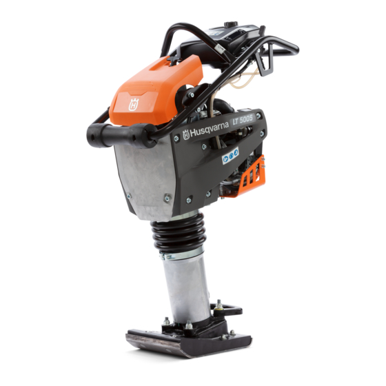
Page 17: Product Overview For Repair And Servicing
6 Product overview for repair and servicing 6.1 Product overview LT 5005, LT 6005, LT 6005 H 1. Fuel tank 11. Fuel filter 2. Air filter latch 12. Oil drain plug 3. Hour meter 13. Oil tank / dipstick 4. Vibration damping units 14. -
Page 18: Product Overview Lt 8005
6.2 Product overview LT 8005 1. Vibration damping units 2. Type plate 3. Throttle control 4. Fuel tank 5. Handle 6. Fuel filter 7. Air filter 8. Starter rope handle 9. Oil tank / dipstick 10. Oil drain plug 11. Rammer leg 12. -
Page 19: Repair And Servicing
• Always use original spare parts. 7.2 Air filter 7.2.1 To clean or replace the air filter LT 5005, LT 6005, LT 6005 H WARNING: Use approved respiratory protection when you clean or replace the air filter. Discard used air filters correctly. The dust in the air filter is dangerous to your health. - Page 20 3. Remove the air filter from the air filter housing. 10. Fold the air filter cover down and put the rubber latch back to the locked position of the air filter cover. Note: Make sure that the rubber latch of the air filter cover is correctly attached.
-
Page 21: Carburetor
LT 6005 H 1. Make sure that the air filter is clean. Refer to clean or replace the air filter LT 5005, LT 6005, LT 6005 H on page 19 . 2. Start the engine and let the engine become warm. - Page 22 7.3.3 To adjust the full throttle speed LT 8005 4. Install 2 washers (A) between the 2 nuts (B) on the throttle cable (C). 1. Make sure that the air filter is clean. Refer to clean or replace the air filter LT 8005 on page 20 . 2.
-
Page 23: Engine
9. Install the spring and the throttle cable stop. 7.4 Engine 7.4.1 To do a check of the engine oil level LT 5005, LT 6005, LT 6005 H 1. Put the product in an upright position. - Page 24 Refer to Technical data container. LT 5005, LT 6005, LT 6005 H on page 49 for the correct type of oil. 7.4.2 To do a check of the engine oil level LT 8005 1. Put the product in an upright position.
- Page 25 7.4.5 To remove and install the engine LT 5005, water. LT 6005, LT 6005 H 1. Remove the 8 bolts and the bottom cover. 1. Put a container below the drain plug for the engine oil.
- Page 26 3. Remove the clamp and disconnect the 2 hoses for 5. Disconnect the hose from the carburetor. the air filter. 6. Remove the screw and the throttle cable. 4. Disconnect the fuel hose. 26 - Repair and servicing 1726 - 001 -...
- Page 27 7. Remove the tape and disconnect the cable. 9. Disconnect the 2 cables and remove the rear cover. 8. Remove the screw on the muffler. 10. Remove the bolt. 1726 - 001 - Repair and servicing - 27...
- Page 28 11. Remove the bolt. 13. Remove the engine. 14. Install in the opposite sequence. Clean the surfaces between the flange and the crankcase before you install the engine. 12. Remove the 4 nuts. 28 - Repair and servicing 1726 - 001 -...
- Page 29 7.4.6 To remove and install the engine LT 8005 3. Remove the throttle cable. 1. Remove the 5 bolts (A) and the bottom cover (B). 2. Remove the throttle cable stop and the spring. 4. Disconnect the hose for the fuel filter and the hose for the fuel tank.
-
Page 30: Handle
5. Remove the 4 nuts and the engine. 7.5.1 To remove and install the handle unit LT 5005, LT 6005, LT 6005 H 1. Remove the 8 bolts and the bottom cover. 6. Install in the opposite sequence. Clean the surfaces between the flange and the crankcase before you install the engine. - Page 31 3. Remove the clamp and disconnect the 2 hoses for 5. Disconnect the hose from the carburetor. the air filter. 6. Remove the screw and the throttle cable. 4. Disconnect the fuel hose. 1726 - 001 - Repair and servicing - 31...
- Page 32 7. Remove the tape and disconnect the cable. 9. Disconnect the 2 cables and remove the rear cover. 8. Remove the screw on the muffler and disconnect the 10. Remove the bolt. cables. 32 - Repair and servicing 1726 - 001 -...
- Page 33 11. Remove the bolt. 13. Remove the handle unit. 14. Install in the opposite sequence. 12. Remove the 4 screws from the bracket. 1726 - 001 - Repair and servicing - 33...
- Page 34 7.5.2 To remove and install the handle unit 3. Disconnect the hose from the fuel filter and the hose from the fuel tank. LT 8005 1. Remove the throttle cable stop and the spring. 4. Remove the 4 screws. 2. Remove the throttle cable. 34 - Repair and servicing 1726 - 001 -...
-
Page 35: Centrifugal Clutch
LT 8005 on page 34 . To remove and install 3. Remove the engine. Refer to the engine LT 5005, LT 6005, LT 6005 H on page 25 To remove and install the engine LT 8005 on page 29 . - Page 36 4. Remove the 4 screws and the cover. Discard the O- 8. Remove the snap ring with snap ring pliers. ring. 5. Remove the snap ring with snap ring pliers. 9. Remove the gear wheel with 2 M8 screws. 6. Remove the crankshaft with a puller. 7.
- Page 37 10. Remove the snap ring from the gear wheel with 12. Remove the needle bearing with a puller. snap ring pliers. 13. Remove the snap ring from the shaft. 11. Remove the bearing with a puller. 1726 - 001 - Repair and servicing - 37...
- Page 38 14. Remove the shaft with a press tool. 17. Remove the needle bearing with a bearing puller. 15. Remove the seal and the snap ring with snap ring pliers. 7.7.2 To assemble the crankcase 1. Clean the parts and surfaces of the crankcase. 2.
- Page 39 3. Install the bearing with a press tool. 7. Install the snap ring with snap ring pliers. 4. Install the snap ring with snap ring pliers. 8. Install the internal snap ring (C) on the shaft. 9. Install the bearing (D) on the gear wheel with a 5.
- Page 40 10. Install the external snap ring with snap ring pliers. 12. Install the internal snap ring with snap ring pliers. 11. Install the gear wheel with a press tool. 13. Install the bearing to the crankshaft with a press tool. 14.
-
Page 41: Rammer Leg And Rammer Shoe
LT 5005, LT 6005, LT 6005 H To remove and install 1. Remove the engine. Refer to the engine LT 5005, LT 6005, LT 6005 H on page 25 . 2. Remove the 4 screws. To remove and install the 16. - Page 42 4. Lift the crankcase and push down the outer tube. 6. Remove the piston bolt. Make sure that there is a distance (A) between the crankcase and outer tube. 7. Remove the spring unit. 5. To keep the distance between the crankcase and the outer tube, put a spacer between the piston rod and the outer tube.
- Page 43 7.8.2 To remove and install spring unit LT 8005 4. Lift the crankcase and push down the outer tube. Make sure that there is a distance (A) between the To remove and install 1. Remove the engine. Refer to crankcase and outer tube. the engine LT 8005 on page 29 .
- Page 44 7. Remove the spring unit. To remove and 1. Remove the spring unit. Refer to install the spring unit LT 5005, LT 6005, LT 6005 H on page 41 and To remove and install spring unit LT 8005 on page 43 .
- Page 45 7.8.4 To remove the bellows for the rammer leg To remove and install 1. Remove the engine. Refer to the engine LT 5005, LT 6005, LT 6005 H on page 25 To remove and install the engine LT 8005 on page 29 .
- Page 46 To remove and install 5. Remove the lower clamp (D). 5. Install the spring unit. Refer to the spring unit LT 5005, LT 6005, LT 6005 H on 6. Remove the bellows. page 41 and To remove and install spring unit LT 8005 on page 43 .
- Page 47 47 . 2. Remove the M8 bolts. 2. Replace the rammer shoe. Note: The LT 5005, LT 6005, LT 6005 H has 8 bolts. The LT 8005 has 14 bolts. 3. Torque the 6 M12 bolts to 78 Nm.
- Page 48 7.8.9 To replace the oil in the rammer leg 1. Put a container below the oil drain plug. 2. Remove the oil drain plug. 3. Let the oil run out into the container. 4. Install the oil drain plug and tighten it. Make sure that the sealing washer is not damaged.
-
Page 49: Technical Data
8 Technical data 8.1 Technical data LT 5005, LT 6005, LT 6005 H LT 5005 LT 6005, LT 6005 H Rammer leg Rammer leg Rammer leg Rammer leg width 153 mm/6 width 230 mm/9 width 230 mm/9 width 280 mm/11 Weight with empty tanks, kg/lb 60/132.3... -
Page 50: Technical Data Lt 8005
8.2 Technical data LT 8005 LT 8005 Rammer shoe width 280 LT 8005 Rammer shoe width 330 mm/11 in. mm/13 in. Weight (uncrated, incl. oil, empty 96/212 97/214 tanks) kg/lb Operation weight (EN500, incl. hy- 98/216 99/218 draulic oil in the rammer leg and ½ fuel tank), kg/lb Engine brand / Type Hatz / 1B20R... - Page 51 1726 - 001 - Technical data - 51...
- Page 52 1142885-26 2021-11-17...