Table of Contents
Advertisement
Quick Links
Intelligent Power Mate
iSitePower-M
Introduction
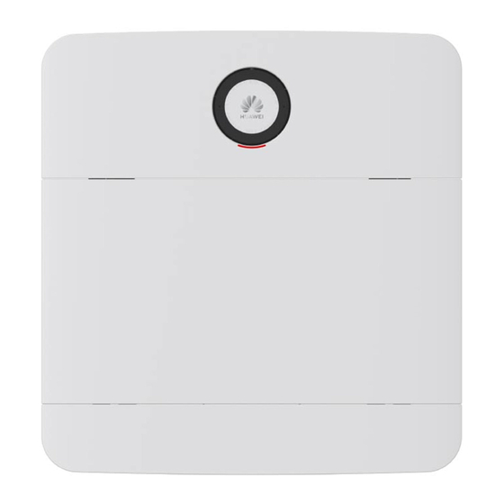
iSitePower-M is a small-scale hybrid power solution. It integrates power supply, backup power, and
management. It is widely used in off-grid and unreliable grid areas and provides reliable and stable
backup power for residences, apartments, shops, and emergency scenarios.
iSitePower-M features a high-density design, small size, light weight, and IP65 protection level. It can
be installed indoors, or on outdoors
Application
Indoor & outdoor scenario, wall-mounted/floor-mounted
Off-grid and unreliable grid areas, civil and commercial backup power
Residences, apartments, shops, and emergency scenarios
Power
Module
Battery
Module
Status
indicator
Advertisement
Table of Contents

Related Manuals for Huawei iSitePower-M ISP-M-MAB05B1


Summary of Contents for Huawei iSitePower-M ISP-M-MAB05B1
- Page 1 Intelligent Power Mate iSitePower-M Introduction iSitePower-M is a small-scale hybrid power solution. It integrates power supply, backup power, and management. It is widely used in off-grid and unreliable grid areas and provides reliable and stable backup power for residences, apartments, shops, and emergency scenarios. iSitePower-M features a high-density design, small size, light weight, and IP65 protection level.
- Page 2 Product parameters Single power module: 700 mm x 246 mm x 152 mm Single battery module: 700 mm x 390 mm x 158 mm Base (mandatory for floor installation): 700 mm x 55 mm x Dimensions (W x H x D) 147 mm Base (mandatory for wall-mounted installation): 700 mm x 118 mm x 184 mm...
- Page 3 Copyright © Huawei Technologies Co., Ltd. 2021. All rights reserved. HUAWEI TECHNOLOGIES CO., LTD. No part of this document may be reproduced or transmitted in any form or by any means without prior written consent of Huawei Huawei Industrial Base Technologies Co., Ltd.
- Page 4 V100R002C00 User Manual (MAP05A1, MAB05B1) Issue Date 2022-10-28 HUAWEI DIGITAL POWER TECHNOLOGIES CO., LTD.
- Page 5 Notice The purchased products, services and features are stipulated by the contract made between Huawei Digital Power Technologies Co., Ltd. and the customer. All or part of the products, services and features described in this document may not be within the purchase scope or the usage scope. Unless otherwise specified in the contract, all statements, information, and recommendations in this document are provided "AS IS"...
-
Page 6: About This Document
Indicates a potentially hazardous situation which, if not avoided, could result in equipment damage, data loss, performance deterioration, or unanticipated results. NOTICE is used to address practices not related to personal injury. Issue 03 (2022-10-28) Copyright © Huawei Digital Power Technologies Co., Ltd. - Page 7 Added the label description. ● Added the description of application scenarios. ● Updated the description of battery recharge. ● Updated some specifications. Issue 01 (2021-09-30) This is the first official release. Issue 03 (2022-10-28) Copyright © Huawei Digital Power Technologies Co., Ltd.
-
Page 8: Table Of Contents
4.4 Solar-Genset Hybrid Scenario............................39 5 System Installation....................... 43 5.1 Installation Preparations..............................43 5.1.1 Checking Before the Installation..........................43 5.1.2 Tools and Instruments..............................44 5.1.3 Determining the Installation Position........................46 Issue 03 (2022-10-28) Copyright © Huawei Digital Power Technologies Co., Ltd. - Page 9 8.3.3 Installing PV Input Power Cables..........................95 8.3.4 Install the AC Output Power Cable..........................96 8.3.5 Install the AC Input Power Cable..........................97 8.3.6 Installing Cables in a Parallel System......................... 99 Issue 03 (2022-10-28) Copyright © Huawei Digital Power Technologies Co., Ltd.
- Page 10 10.5 Storage with Low SOC..............................152 11 FAQs............................. 154 11.1 Uneven Ground During the Installation........................154 11.2 Tools for Preparing PV Cables............................154 11.3 Special Cables..................................154 11.4 Removing Power Terminals............................154 11.5 Power-On.................................... 155 Issue 03 (2022-10-28) Copyright © Huawei Digital Power Technologies Co., Ltd.
- Page 11 B Preparing the Cable and Terminal..................162 B.1 Preparing a Cord End Terminal............................. 162 B.2 Preparing an OT Terminal............................... 162 B.3 Preparing a PV Input Power Cable..........................163 B.4 Stripping Length................................. 164 Issue 03 (2022-10-28) Copyright © Huawei Digital Power Technologies Co., Ltd.
-
Page 12: Safety Precautions
Equipment damage due to force majeure, such as earthquakes, fire, and storms ● Damage caused during transportation by the customer ● Damage caused by storage conditions that do not meet the requirements specified in related documents Issue 03 (2022-10-28) Copyright © Huawei Digital Power Technologies Co., Ltd. - Page 13 ● In the case of a fire, immediately leave the building or the equipment area, and turn on the fire alarm bell or make an emergency call. Do not enter the building on fire in any case. Issue 03 (2022-10-28) Copyright © Huawei Digital Power Technologies Co., Ltd.
-
Page 14: Personnel Requirements
You shall not reverse engineer, decompile, disassemble, adapt, add code to the device software or alter the device software in any other way, research the internal implementation of the device, obtain the device software source code, infringe on Huawei's intellectual property, or disclose any device software performance test results. - Page 15 To ensure safety, comply with the following requirements: – Cables can be laid or installed only when the temperature is higher than 0°C. Handle cables with caution, especially at a low temperature. Issue 03 (2022-10-28) Copyright © Huawei Digital Power Technologies Co., Ltd.
-
Page 16: Battery Safety
Batteries are not maintained based on the operation guide, such as failure to check battery terminals regularly. ● Batteries are stolen. ● The warranty period of batteries has expired. Issue 03 (2022-10-28) Copyright © Huawei Digital Power Technologies Co., Ltd. - Page 17 ● Use tools correctly to avoid hurting people or damaging the equipment. Issue 03 (2022-10-28) Copyright © Huawei Digital Power Technologies Co., Ltd.
- Page 18 During installation, ensure that the screws are tightened properly using a torque wrench and check them regularly. ● After installing the equipment, remove idle packing materials such as cartons, foam, plastics, and cable ties from the equipment area. Issue 03 (2022-10-28) Copyright © Huawei Digital Power Technologies Co., Ltd.
- Page 19 ● Overheating may cause batteries to deform and leak corrosive electrolyte or toxic gas. Keep away from the batteries to avoid skin irritation and chemical burns. Issue 03 (2022-10-28) Copyright © Huawei Digital Power Technologies Co., Ltd.
- Page 20 If the batteries leak or are damaged, contact technical support or a battery recycling company for disposal. ● If the batteries are out of service life, contact a battery recycling company for disposal. Issue 03 (2022-10-28) Copyright © Huawei Digital Power Technologies Co., Ltd.
-
Page 21: Storage Requirements
The batteries must be protected against rain and water. ● Relative humidity: 5% to 80% ● Keep batteries away from direct sunlight. Issue 03 (2022-10-28) Copyright © Huawei Digital Power Technologies Co., Ltd. -
Page 22: Transportation Requirements
Being dampened by rains, snows, or falling into water ● Falling or mechanical impact ● Being upside-down or tilted NO TE If any of the preceding exceptions occurs, take the emergency measures. Issue 03 (2022-10-28) Copyright © Huawei Digital Power Technologies Co., Ltd. -
Page 23: Installation Environment Requirements
A salt-affected area refers to the region within 500 meters from the coast or prone to sea breeze. The regions prone to sea breeze vary with weather conditions (such as typhoons and monsoons) or terrains (such as dams and hills). Issue 03 (2022-10-28) Copyright © Huawei Digital Power Technologies Co., Ltd. -
Page 24: Mechanical Safety
Ensure that the ladder is securely positioned. The recommended angle for a ladder against the floor is 75 degrees, as shown in the following figure. An angle rule can be used to measure the angle. Issue 03 (2022-10-28) Copyright © Huawei Digital Power Technologies Co., Ltd. -
Page 25: Commissioning
When the equipment is powered on for the first time, ensure that professional personnel set parameters correctly. Incorrect settings may result in inconsistency with local certification and affect the normal operation of the equipment. Issue 03 (2022-10-28) Copyright © Huawei Digital Power Technologies Co., Ltd. -
Page 26: Maintenance And Replacement
Take out all external tools and parts from the equipment after maintenance is complete. ● If the equipment is not used for a long time, store and recharge batteries according to this document. Issue 03 (2022-10-28) Copyright © Huawei Digital Power Technologies Co., Ltd. -
Page 27: Product Description
Table 2-1 Model description Meaning Value Product label iSitePower-M: hybrid power supply series Version MA: product version Module type P: power module Power level 05: 5kW Design code A1: module number Issue 03 (2022-10-28) Copyright © Huawei Digital Power Technologies Co., Ltd. -
Page 28: Appearance
MA: product version Module type B: battery module Power level 05: 5kWh Design code B1: module number 2.2 Appearance Figure 2-3 Appearance (1) LED indicator (2) Power module (3) Decorative cover Issue 03 (2022-10-28) Copyright © Huawei Digital Power Technologies Co., Ltd. - Page 29 Indicates the battery capacity and that the strip light green product is discharging. NOTE A part of the strip light dims when every 10% of battery power is consumed. Issue 03 (2022-10-28) Copyright © Huawei Digital Power Technologies Co., Ltd.
-
Page 30: System Networking
User Manual (MAP05A1, MAB05B1) 2 Product Description Indicator Status Description Blinking green at Indicates that the product is being charging. an interval of 1.25s 2.3 System Networking Figure 2-5 Networking diagram Issue 03 (2022-10-28) Copyright © Huawei Digital Power Technologies Co., Ltd. - Page 31 (D) Power distribution box (PDB) (E) Load (F) DG (G) Power grid (I) Power distribution cabinet (PDC) The system supports capacity expansion and power expansion. Figure 2-6 System configurations Issue 03 (2022-10-28) Copyright © Huawei Digital Power Technologies Co., Ltd.
- Page 32 In a parallel system, if the number of battery modules in the master product is different from that in the slave product (not recommended), for example, two power modules and five battery modules, the power/capacity of battery modules is 9 kW/25 kWh. Issue 03 (2022-10-28) Copyright © Huawei Digital Power Technologies Co., Ltd.
-
Page 33: Label Description
Refer to Reminds operators to documentation refer to the documentation of the battery module. Operation warning Do not remove the connector when the product is running. Issue 03 (2022-10-28) Copyright © Huawei Digital Power Technologies Co., Ltd. - Page 34 Scan the QR code to connect to the WiFi network of the product and log in to the product to set parameters locally. NO TE The labels are for reference only. Issue 03 (2022-10-28) Copyright © Huawei Digital Power Technologies Co., Ltd.
-
Page 35: Components
(2) PV input ports (3) Battery input ports maintenance switch) (4) COM-PAR (5) COM-BAT (6) Reserved port (communications port between (communications port between parallel power modules) power module and battery module) Issue 03 (2022-10-28) Copyright © Huawei Digital Power Technologies Co., Ltd. - Page 36 Pin 1 Pin 2 (A) Pin 3 (B) Pin 4 (C) Remarks Power (M/S) Module Address Master address Slave address Slave address COM and Dry Contacts Figure 3-4 Wiring terminals Issue 03 (2022-10-28) Copyright © Huawei Digital Power Technologies Co., Ltd.
- Page 37 Password reset will result in system restart, which may interrupt the power supply to loads. Therefore, you are advised not to reset the passwords when power is supplying to loads. Issue 03 (2022-10-28) Copyright © Huawei Digital Power Technologies Co., Ltd.
- Page 38 Table 3-4 COM-PAR pin definitions Signal Description Synchronization Parallel synchronization signal signal 1+ Synchronization signal 1– Synchronization signal 2+ Synchronization signal 2– Synchronization signal 3+ Synchronization signal 3– CANH Parallel high-speed CAN CANL Issue 03 (2022-10-28) Copyright © Huawei Digital Power Technologies Co., Ltd.
-
Page 39: Battery Module
Table 3-6 Pin definitions for the FE port Signal Description Transmit data over FE. Receive data over FE. 4, 5, 7, 8 Null 3.2 Battery Module The standard capacity is 5 kWh. Figure 3-5 Appearance Issue 03 (2022-10-28) Copyright © Huawei Digital Power Technologies Co., Ltd. - Page 40 The preceding port is protected by security mechanisms. Table 3-8 COM pin definition Signal Description START+ Manual ON/OFF switch START- Null Null Null Null CANH CAN bus high level Issue 03 (2022-10-28) Copyright © Huawei Digital Power Technologies Co., Ltd.
-
Page 41: Optional) Ac Parallel Box Acdb220-90-1B
Figure 3-8 ACDB220-90-1B interior (1) Ground point on the door (2) Ground bar (3) Cable bags (4) AC input circuit breaker (5) N wiring terminal (6) AC output circuit breaker Issue 03 (2022-10-28) Copyright © Huawei Digital Power Technologies Co., Ltd. -
Page 42: Application Scenarios
Method 3: Charge the battery module at high irradiance for a maximum of half an hour, it can start properly. If it does not start and no alarm is generated during the charging period, please wait. Issue 03 (2022-10-28) Copyright © Huawei Digital Power Technologies Co., Ltd. -
Page 43: Solar-Only Scenario
In the solar-only scenario, the power system works circularly as follows. The power source preference sequence is solar power > battery. If the solar power is greater than the load power, solar power is supplied to loads and charges batteries. Issue 03 (2022-10-28) Copyright © Huawei Digital Power Technologies Co., Ltd. -
Page 44: Grid Scenario
If the solar power is less than the load power, solar power and battery power are supplied to loads at the same time. If there is no solar power, batteries power loads. 4.2 Grid Scenario Figure 4-3 Grid scenario network diagram (one product) Issue 03 (2022-10-28) Copyright © Huawei Digital Power Technologies Co., Ltd. - Page 45 If grid power is available, grid power is supplied to loads and charges batteries if batteries are not fully charged. If grid power is unavailable or abnormal (such as abnormal frequency, overvoltage, or undervoltage), batteries supply power to loads. Issue 03 (2022-10-28) Copyright © Huawei Digital Power Technologies Co., Ltd.
-
Page 46: Solar-Grid Hybrid Scenario
V100R002C00 User Manual (MAP05A1, MAB05B1) 4 Application Scenarios 4.3 Solar-Grid Hybrid Scenario Figure 4-5 Solar-grid hybrid scenario network diagram (one product) Issue 03 (2022-10-28) Copyright © Huawei Digital Power Technologies Co., Ltd. - Page 47 When solar power is unavailable but grid power is available, grid power is supplied to loads and batteries. When both solar power and grid power are unavailable, batteries supply power to loads. Issue 03 (2022-10-28) Copyright © Huawei Digital Power Technologies Co., Ltd.
- Page 48 V100R002C00 User Manual (MAP05A1, MAB05B1) 4 Application Scenarios Figure 4-7 Setting Discharge DOD for a single-node system Issue 03 (2022-10-28) Copyright © Huawei Digital Power Technologies Co., Ltd.
- Page 49 4 Application Scenarios Figure 4-8 Setting Discharge DOD for a parallel system Parameter Description Value Range Discharge DOD Set the battery depth of 5–90 discharge. The default value is 85. Issue 03 (2022-10-28) Copyright © Huawei Digital Power Technologies Co., Ltd.
-
Page 50: Solar-Genset Hybrid Scenario
The default value is 0.4. 4.4 Solar-Genset Hybrid Scenario Figure 4-9 Solar-genset hybrid scenario network diagram (one product) Issue 03 (2022-10-28) Copyright © Huawei Digital Power Technologies Co., Ltd. - Page 51 When solar power is unavailable, batteries supply power to loads. When the batteries stop discharging when DOD to Start is reached, the genset is started. Issue 03 (2022-10-28) Copyright © Huawei Digital Power Technologies Co., Ltd.
- Page 52 DOD to Start is reached. No Control Mode: The genset startup/shutdown is performed manually. Minimum Charge Set the minimum charge 0–2880 Duration time. The default value is Issue 03 (2022-10-28) Copyright © Huawei Digital Power Technologies Co., Ltd.
- Page 53 The default value is 4. Enable Timed Genset Set whether to shut Disable, Enable Stop down the genset on schedule. The default value is Disable. Issue 03 (2022-10-28) Copyright © Huawei Digital Power Technologies Co., Ltd.
-
Page 54: System Installation
If any item is missing or damaged, contact your dealer. NO TE For details about the number of deliverables, see the Packing List in the packing case. Issue 03 (2022-10-28) Copyright © Huawei Digital Power Technologies Co., Ltd. -
Page 55: Tools And Instruments
Diagonal pliers Wire stripper Flat-head insulated torque screwdriver Phillips insulated Rubber mallet Utility knife torque screwdriver Crimping tool, Cord end terminal Cable cutter model: PV-CZM- crimping tool CZM41100 (preferred)/ CZM22100 Issue 03 (2022-10-28) Copyright © Huawei Digital Power Technologies Co., Ltd. - Page 56 (model: PV-MS- HZ open-end wrench) Multimeter (DC Marker Steel measuring voltage tape measurement range ≥ 600 V Level Hydraulic pliers Heat shrink tubing Heat gun Protective gloves Goggles Anti-dust mask Issue 03 (2022-10-28) Copyright © Huawei Digital Power Technologies Co., Ltd.
-
Page 57: Determining The Installation Position
● The bearing capacity of the ground must be greater than or equal to 500 kg/m Installation Dimensions Reserve sufficient clearance around the product for installation and heat dissipation. Issue 03 (2022-10-28) Copyright © Huawei Digital Power Technologies Co., Ltd. - Page 58 V100R002C00 User Manual (MAP05A1, MAB05B1) 5 System Installation Figure 5-1 Installation dimensions for one product Figure 5-2 Installation space for a parallel system or capacity expansion scenario Issue 03 (2022-10-28) Copyright © Huawei Digital Power Technologies Co., Ltd.
-
Page 59: Installing A Mounting Bracket
Step 1 Cut the marking-off template along the dotted line. Figure 5-3 Cutting the marking-off template Step 2 Mark mounting holes for the base. Issue 03 (2022-10-28) Copyright © Huawei Digital Power Technologies Co., Ltd. - Page 60 Figure 5-5 Marking the mounting holes for battery modules Step 4 Drill holes and install expansion bolts. D ANGER When drilling holes, avoid the water pipes and power cables buried in the wall. Issue 03 (2022-10-28) Copyright © Huawei Digital Power Technologies Co., Ltd.
- Page 61 (the weight of one battery module is 50 kg) are met and appropriate bolts are selected. Figure 5-7 M6 expansion bolt structure (1) Bolt (2) Nut (3) Spring washer (4) Flat washer (5) Expansion sleeve Issue 03 (2022-10-28) Copyright © Huawei Digital Power Technologies Co., Ltd.
-
Page 62: Wall Mounting
Figure 5-8 Standard mounting holes Step 2 Drill holes and install expansion bolts. D ANGER When drilling holes, avoid the water pipes and power cables buried in the wall. Issue 03 (2022-10-28) Copyright © Huawei Digital Power Technologies Co., Ltd. - Page 63 M6 stainless steel expansion bolts by yourself. Figure 5-9 Installing expansion bolts Step 3 Install a wall-mounting bracket. Figure 5-10 Installing a wall-mounting bracket Step 4 Install a wall-mounting bracket cover. Issue 03 (2022-10-28) Copyright © Huawei Digital Power Technologies Co., Ltd.
-
Page 64: Installing Modules
● Two persons are required to move a module. ● Battery modules must be secured to the wall. Installing Modules Step 1 Install a battery module on the base. Figure 5-12 Installing a battery module Issue 03 (2022-10-28) Copyright © Huawei Digital Power Technologies Co., Ltd. - Page 65 Step 3 Install the remaining battery modules and power module from bottom to top. Each time a module is installed, tighten the screws on the left and right, and then secure it against the wall. Figure 5-14 Ground mounting completed Issue 03 (2022-10-28) Copyright © Huawei Digital Power Technologies Co., Ltd.
-
Page 66: Optional) Installing Battery Modules For Capacity Expansion
Step 1 Remove the L-shaped plates from the top cover, rotate them by 180 degrees, and install them back on the top cover. Figure 5-16 Rotating the L-shaped sheets on the top cover Step 2 Install the top cover on the battery module. Issue 03 (2022-10-28) Copyright © Huawei Digital Power Technologies Co., Ltd. -
Page 67: Optional) Installing An Ac Parallel Box
5.5 (Optional) Installing an AC Parallel Box Prerequisites In a parallel system, an AC parallel box must be configured. Step 1 Mark mounting holes. Figure 5-18 Marking mounting holes Step 2 Install expansion bolts. Issue 03 (2022-10-28) Copyright © Huawei Digital Power Technologies Co., Ltd. - Page 68 User Manual (MAP05A1, MAB05B1) 5 System Installation Figure 5-19 Installing expansion bolts Step 3 Install the AC parallel box on the wall. Figure 5-20 Installing the AC parallel box ----End Issue 03 (2022-10-28) Copyright © Huawei Digital Power Technologies Co., Ltd.
-
Page 69: Setting The Dip Switch
● The default address is 0 (Pin 1 to Pin 4: OFF). Step 1 Open the power module maintenance compartment. Figure 6-1 Open maintenance compartment Step 2 Set the DIP switch address. Issue 03 (2022-10-28) Copyright © Huawei Digital Power Technologies Co., Ltd. - Page 70 V100R002C00 User Manual (MAP05A1, MAB05B1) 6 Setting the DIP Switch Figure 6-2 Set the DIP switch address ----End Issue 03 (2022-10-28) Copyright © Huawei Digital Power Technologies Co., Ltd.
-
Page 71: Preparing Cables
Outdoor shielded twisted pair cable Ground cable Outdoor single-core copper cable (standard scenario) NO TICE In capacity expansion scenarios, you need to purchase power cables and signal cables for bottom cascading from Huawei. Issue 03 (2022-10-28) Copyright © Huawei Digital Power Technologies Co., Ltd. -
Page 72: Cables Prepared By The Customer
(customer side) sectional area of the AC input power cable) Ground Ground point Outdoor single-core Main ground cable: 6 mm point on the copper cable module for capacity expansion Issue 03 (2022-10-28) Copyright © Huawei Digital Power Technologies Co., Ltd. -
Page 73: Grid Scenario
● Cable outer diameter: 13.7–16.9 mm AC input Outdoor three-core copper ● Conductor cross- cable (L/N/PE) sectional area: 4–6 mm (customer side) ● Cable outer diameter: 13.7–16.9 mm Issue 03 (2022-10-28) Copyright © Huawei Digital Power Technologies Co., Ltd. - Page 74 ● Cable outer diameter: 16–26 mm AC parallel Ground bar Outdoor single-core ● Conductor cross- copper cable sectional area: 25 mm (customer side) ● Cable outer diameter: 8– 11 mm Issue 03 (2022-10-28) Copyright © Huawei Digital Power Technologies Co., Ltd.
-
Page 75: Solar-Grid Hybrid Scenario
● Cable outer diameter: 5.5–9 mm Ground Ground bar Outdoor single-core Main ground cable: 4–6 point copper cable (same as the cross- (customer side) sectional area of the AC input power cable) Issue 03 (2022-10-28) Copyright © Huawei Digital Power Technologies Co., Ltd. -
Page 76: Solar-Genset Hybrid Scenario
● Cable outer diameter: 13.7–16.9 mm AC input Outdoor three-core copper ● Conductor cross- cable (L/N/PE) sectional area: 4–6 mm (customer side) ● Cable outer diameter: 13.7–16.9 mm Issue 03 (2022-10-28) Copyright © Huawei Digital Power Technologies Co., Ltd. - Page 77 ● Cable outer diameter: 16–26 mm AC parallel AC output Outdoor three-core copper ● Conductor cross- cable (L/N/PE) sectional area: 4–6 mm ● Cable outer diameter: 13.7–16.9 mm Issue 03 (2022-10-28) Copyright © Huawei Digital Power Technologies Co., Ltd.
- Page 78 ● Cable outer diameter: 16–26 mm AC parallel Ground bar Outdoor single-core ● Conductor cross- copper cable (customer sectional area: 25 mm side) ● Cable outer diameter: 8– 11 mm Issue 03 (2022-10-28) Copyright © Huawei Digital Power Technologies Co., Ltd.
-
Page 79: Electrical Connection
The cable colors shown in the electrical connection diagrams provided in this chapter are for reference only. Select cables in accordance with local cable specifications (green and yellow cables are only used for protective grounding). 8.1 Solar-Only Scenario Issue 03 (2022-10-28) Copyright © Huawei Digital Power Technologies Co., Ltd. -
Page 80: Installing Ground Cables
8.1.1 Installing Ground Cables Precautions D ANGER Ensure that the ground cable is securely connected. Otherwise, electric shocks may occur. Procedure Step 1 Install ground cables. Figure 8-1 Installing ground cables ----End Issue 03 (2022-10-28) Copyright © Huawei Digital Power Technologies Co., Ltd. -
Page 81: Installing The Internal Cable
When a communications terminal is connected to a single network cable, a waterproof rubber plug must be installed. Procedure Step 1 Install ground cables. Figure 8-2 Installing ground cables Step 2 Installing battery module power cables. Issue 03 (2022-10-28) Copyright © Huawei Digital Power Technologies Co., Ltd. - Page 82 Lock the communications terminal waterproof gland,Reinstall the waterproof rubber plug. Tighten the locking cap and secure the signal cables using cable clips. Step 4 Install communications cables for other battery modules in sequence. Issue 03 (2022-10-28) Copyright © Huawei Digital Power Technologies Co., Ltd.
-
Page 83: Installing Pv Input Power Cables
Step 1 Use a removal wrench to remove the waterproof gland from the PV input terminal on the power module. NO TE Take out the removal wrench from the decorative cover delivered with the product. Step 2 Install the PV input power cables. Issue 03 (2022-10-28) Copyright © Huawei Digital Power Technologies Co., Ltd. -
Page 84: Install The Ac Output Power Cable
In a single-node system, connect the other end of the AC output power cable to a PDB. In a parallel system, connect the other end of the AC output power cable to the AC parallel box. Procedure Step 1 Connect AC power cables to the terminal connectors. Issue 03 (2022-10-28) Copyright © Huawei Digital Power Technologies Co., Ltd. -
Page 85: Installing Cables In A Parallel System
Figure 8-7 Installing an AC output power cable ----End 8.1.5 Installing Cables in a Parallel System 8.1.5.1 Installing a Ground Cable for the Parallel Box Procedure Step 1 Install a ground cable. Issue 03 (2022-10-28) Copyright © Huawei Digital Power Technologies Co., Ltd. -
Page 86: Installing Ac Output Power Cables In A Parallel System
● The three cables from the AC output circuit breaker to the power modules must be of the same length. Procedure Step 1 Install AC output power cables of the parallel box. Issue 03 (2022-10-28) Copyright © Huawei Digital Power Technologies Co., Ltd. - Page 87 V100R002C00 User Manual (MAP05A1, MAB05B1) 8 Electrical Connection Figure 8-9 Install AC output power cables of the parallel box Issue 03 (2022-10-28) Copyright © Huawei Digital Power Technologies Co., Ltd.
-
Page 88: Installing Communications Cables In A Parallel System
Step 1 Install communications cables between parallel power modules. Figure 8-10 Installing communications cables (1) Build-out resistor Step 2 Connect the FE ports of the master and slave devices using a network cable. Issue 03 (2022-10-28) Copyright © Huawei Digital Power Technologies Co., Ltd. -
Page 89: Grid Scenario
8.2 Grid Scenario 8.2.1 Installing Ground Cables Precautions D ANGER Ensure that the ground cable is securely connected. Otherwise, electric shocks may occur. Procedure Step 1 Install ground cables. Issue 03 (2022-10-28) Copyright © Huawei Digital Power Technologies Co., Ltd. -
Page 90: Installing The Internal Cable
NO TICE When a communications terminal is connected to a single network cable, a waterproof rubber plug must be installed. Procedure Step 1 Install ground cables. Issue 03 (2022-10-28) Copyright © Huawei Digital Power Technologies Co., Ltd. - Page 91 Install battery module power cables. Use a removal wrench to remove the waterproof glands from the battery terminals on the power module. Install power cables between the battery modules and power module. Issue 03 (2022-10-28) Copyright © Huawei Digital Power Technologies Co., Ltd.
- Page 92 Lock the communications terminal waterproof gland,Reinstall the waterproof rubber plug. Tighten the locking cap and secure the signal cables using cable clips. Step 4 Install communications cables for other battery modules in sequence. Issue 03 (2022-10-28) Copyright © Huawei Digital Power Technologies Co., Ltd.
-
Page 93: Install The Ac Output Power Cable
A leakage protection device must be configured for the AC output of the system. The leakage current must be 30 mA. You need to configure and install the device by yourself. Issue 03 (2022-10-28) Copyright © Huawei Digital Power Technologies Co., Ltd. - Page 94 Figure 8-16 Connecting cables to terminals Step 2 Install the AC output power cable and secure the cable using cable clips. Figure 8-17 Installing an AC output power cable ----End Issue 03 (2022-10-28) Copyright © Huawei Digital Power Technologies Co., Ltd.
-
Page 95: Install The Ac Input Power Cable
Step 1 Connect AC power cables to the terminal connectors. Figure 8-18 Connecting cables to terminals Step 2 Install the AC input power cable and secure the cable using cable clips. Issue 03 (2022-10-28) Copyright © Huawei Digital Power Technologies Co., Ltd. -
Page 96: Installing Cables In A Parallel System
Figure 8-19 Installing an AC input power cable ----End 8.2.5 Installing Cables in a Parallel System 8.2.5.1 Installing a Ground Cable for the Parallel Box Procedure Step 1 Install a ground cable. Issue 03 (2022-10-28) Copyright © Huawei Digital Power Technologies Co., Ltd. -
Page 97: Installing Ac Input Power Cables In A Parallel System
● The three cables from the AC input circuit breaker to the power modules must be of the same length. Procedure Step 1 Install AC input power cables of the parallel box. Issue 03 (2022-10-28) Copyright © Huawei Digital Power Technologies Co., Ltd. - Page 98 V100R002C00 User Manual (MAP05A1, MAB05B1) 8 Electrical Connection Figure 8-21 Install AC input power cables of the parallel box (1) Short-circuit plate (2) PDC ----End Issue 03 (2022-10-28) Copyright © Huawei Digital Power Technologies Co., Ltd.
-
Page 99: Installing Ac Output Power Cables In A Parallel System
● The three cables from the AC output circuit breaker to the power modules must be of the same length. Procedure Step 1 Install AC output power cables of the parallel box. Issue 03 (2022-10-28) Copyright © Huawei Digital Power Technologies Co., Ltd. - Page 100 V100R002C00 User Manual (MAP05A1, MAB05B1) 8 Electrical Connection Figure 8-22 Install AC output power cables of the parallel box Issue 03 (2022-10-28) Copyright © Huawei Digital Power Technologies Co., Ltd.
-
Page 101: Installing Communications Cables In A Parallel System
Step 1 Install communications cables between parallel power modules. Figure 8-23 Installing communications cables (1) Build-out resistor Step 2 Connect the FE ports of the master and slave devices using a network cable. Issue 03 (2022-10-28) Copyright © Huawei Digital Power Technologies Co., Ltd. -
Page 102: Solar-Grid Hybrid Scenario
8.3 Solar-Grid Hybrid Scenario 8.3.1 Installing Ground Cables Precautions D ANGER Ensure that the ground cable is securely connected. Otherwise, electric shocks may occur. Procedure Step 1 Install ground cables. Issue 03 (2022-10-28) Copyright © Huawei Digital Power Technologies Co., Ltd. -
Page 103: Installing The Internal Cable
NO TICE When a communications terminal is connected to a single network cable, a waterproof rubber plug must be installed. Procedure Step 1 Install ground cables. Issue 03 (2022-10-28) Copyright © Huawei Digital Power Technologies Co., Ltd. - Page 104 Install battery module power cables. Use a removal wrench to remove the waterproof glands from the battery terminals on the power module. Install power cables between the battery modules and power module. Issue 03 (2022-10-28) Copyright © Huawei Digital Power Technologies Co., Ltd.
- Page 105 Lock the communications terminal waterproof gland,Reinstall the waterproof rubber plug. Tighten the locking cap and secure the signal cables using cable clips. Step 4 Install communications cables for other battery modules in sequence. Issue 03 (2022-10-28) Copyright © Huawei Digital Power Technologies Co., Ltd.
-
Page 106: Installing Pv Input Power Cables
Step 1 Use a removal wrench to remove the waterproof gland from the PV input terminal on the power module. NO TE Take out the removal wrench from the decorative cover delivered with the product. Step 2 Install the PV input power cables. Issue 03 (2022-10-28) Copyright © Huawei Digital Power Technologies Co., Ltd. -
Page 107: Install The Ac Output Power Cable
In a single-node system, connect the other end of the AC output power cable to a PDB. In a parallel system, connect the other end of the AC output power cable to the AC parallel box. Procedure Step 1 Connect AC power cables to the terminal connectors. Issue 03 (2022-10-28) Copyright © Huawei Digital Power Technologies Co., Ltd. -
Page 108: Install The Ac Input Power Cable
● Do not reversely connect or short-circuit the live wire and neutral wire of an AC power cable. ● The PE wire of an AC power cable must be grounded. ● Do not reversely connect AC input power cables. Issue 03 (2022-10-28) Copyright © Huawei Digital Power Technologies Co., Ltd. - Page 109 Step 1 Connect AC power cables to the terminal connectors. Figure 8-32 Connecting cables to terminals Step 2 Install the AC input power cable and secure the cable using cable clips. Issue 03 (2022-10-28) Copyright © Huawei Digital Power Technologies Co., Ltd.
-
Page 110: Installing Cables In A Parallel System
Figure 8-33 Installing an AC input power cable ----End 8.3.6 Installing Cables in a Parallel System 8.3.6.1 Installing a Ground Cable for the Parallel Box Procedure Step 1 Install a ground cable. Issue 03 (2022-10-28) Copyright © Huawei Digital Power Technologies Co., Ltd. -
Page 111: Installing Ac Input Power Cables In A Parallel System
● The three cables from the AC input circuit breaker to the power modules must be of the same length. Procedure Step 1 Install AC input power cables of the parallel box. Issue 03 (2022-10-28) Copyright © Huawei Digital Power Technologies Co., Ltd. - Page 112 V100R002C00 User Manual (MAP05A1, MAB05B1) 8 Electrical Connection Figure 8-35 Install AC input power cables of the parallel box (1) Short-circuit plate (2) PDC ----End Issue 03 (2022-10-28) Copyright © Huawei Digital Power Technologies Co., Ltd.
-
Page 113: Installing Ac Output Power Cables In A Parallel System
● The three cables from the AC output circuit breaker to the power modules must be of the same length. Procedure Step 1 Install AC output power cables of the parallel box. Issue 03 (2022-10-28) Copyright © Huawei Digital Power Technologies Co., Ltd. - Page 114 V100R002C00 User Manual (MAP05A1, MAB05B1) 8 Electrical Connection Figure 8-36 Install AC output power cables of the parallel box Issue 03 (2022-10-28) Copyright © Huawei Digital Power Technologies Co., Ltd.
-
Page 115: Installing Communications Cables In A Parallel System
Step 1 Install communications cables between parallel power modules. Figure 8-37 Installing communications cables (1) Build-out resistor Step 2 Connect the FE ports of the master and slave devices using a network cable. Issue 03 (2022-10-28) Copyright © Huawei Digital Power Technologies Co., Ltd. -
Page 116: Solar-Genset Hybrid Scenario
8.4 Solar-Genset Hybrid Scenario 8.4.1 Installing Ground Cables Precautions D ANGER Ensure that the ground cable is securely connected. Otherwise, electric shocks may occur. Procedure Step 1 Install ground cables. Issue 03 (2022-10-28) Copyright © Huawei Digital Power Technologies Co., Ltd. -
Page 117: Installing The Internal Cable
NO TICE When a communications terminal is connected to a single network cable, a waterproof rubber plug must be installed. Procedure Step 1 Install ground cables. Issue 03 (2022-10-28) Copyright © Huawei Digital Power Technologies Co., Ltd. - Page 118 Install battery module power cables. Use a removal wrench to remove the waterproof glands from the battery terminals on the power module. Install power cables between the battery modules and power module. Issue 03 (2022-10-28) Copyright © Huawei Digital Power Technologies Co., Ltd.
- Page 119 Lock the communications terminal waterproof gland,Reinstall the waterproof rubber plug. Tighten the locking cap and secure the signal cables using cable clips. Step 4 Install communications cables for other battery modules in sequence. Issue 03 (2022-10-28) Copyright © Huawei Digital Power Technologies Co., Ltd.
-
Page 120: Installing Pv Input Power Cables
Step 1 Use a removal wrench to remove the waterproof gland from the PV input terminal on the power module. NO TE Take out the removal wrench from the decorative cover delivered with the product. Step 2 Install the PV input power cables. Issue 03 (2022-10-28) Copyright © Huawei Digital Power Technologies Co., Ltd. -
Page 121: Install The Ac Output Power Cable
In a single-node system, connect the other end of the AC output power cable to a PDB. In a parallel system, connect the other end of the AC output power cable to the AC parallel box. Procedure Step 1 Connect AC power cables to the terminal connectors. Issue 03 (2022-10-28) Copyright © Huawei Digital Power Technologies Co., Ltd. -
Page 122: Install The Ac Input Power Cable
● Do not reversely connect or short-circuit the live wire and neutral wire of an AC power cable. ● The PE wire of an AC power cable must be grounded. ● Do not reversely connect AC input power cables. Issue 03 (2022-10-28) Copyright © Huawei Digital Power Technologies Co., Ltd. - Page 123 Step 1 Connect AC power cables to the terminal connectors. Figure 8-46 Connecting cables to terminals Step 2 Install the AC input power cable and secure the cable using cable clips. Issue 03 (2022-10-28) Copyright © Huawei Digital Power Technologies Co., Ltd.
-
Page 124: Installing Genset Control Signal Cables
NO and COM. For a genset that starts when the dry contact is closed, connect the signal cable to ports NC and COM. Procedure Step 1 Install genset control signal cables. Issue 03 (2022-10-28) Copyright © Huawei Digital Power Technologies Co., Ltd. -
Page 125: Installing Cables In A Parallel System
8.4.7 Installing Cables in a Parallel System 8.4.7.1 Installing a Ground Cable for the Parallel Box Procedure Step 1 Install a ground cable. Figure 8-49 Installing a ground cable ----End Issue 03 (2022-10-28) Copyright © Huawei Digital Power Technologies Co., Ltd. -
Page 126: Installing Ac Input Power Cables In A Parallel System
● The three cables from the AC input circuit breaker to the power modules must be of the same length. Procedure Step 1 Install AC input power cables of the parallel box. Figure 8-50 Install AC input power cables of the parallel box Issue 03 (2022-10-28) Copyright © Huawei Digital Power Technologies Co., Ltd. -
Page 127: Installing Ac Output Power Cables In A Parallel System
● The three cables from the AC output circuit breaker to the power modules must be of the same length. Procedure Step 1 Install AC output power cables of the parallel box. Issue 03 (2022-10-28) Copyright © Huawei Digital Power Technologies Co., Ltd. - Page 128 V100R002C00 User Manual (MAP05A1, MAB05B1) 8 Electrical Connection Figure 8-51 Install AC output power cables of the parallel box Issue 03 (2022-10-28) Copyright © Huawei Digital Power Technologies Co., Ltd.
-
Page 129: Installing Communications Cables In A Parallel System
Step 1 Install communications cables between parallel power modules. Figure 8-52 Installing communications cables (1) Build-out resistor Step 2 Connect the FE ports of the master and slave devices using a network cable. Issue 03 (2022-10-28) Copyright © Huawei Digital Power Technologies Co., Ltd. -
Page 130: Optional) Installing Cables In Capacity Expansion Scenario
● Cables outside the device must be routed through cable pipes. 8.5.1 Installing Ground Cables D ANGER Ensure that the ground cable is securely connected. Otherwise, electric shocks may occur. Procedure Step 1 Install ground cables. Issue 03 (2022-10-28) Copyright © Huawei Digital Power Technologies Co., Ltd. -
Page 131: Installing The Internal Cable
NO TICE When a communications terminal is connected to a single network cable, a waterproof rubber plug must be installed. Procedure Step 1 Installing battery module power cables. Issue 03 (2022-10-28) Copyright © Huawei Digital Power Technologies Co., Ltd. - Page 132 Lock the communications terminal waterproof gland. Reinstall the waterproof rubber plug. Tighten the locking cap and secure the signal cables using cable clips. Step 3 Install communications cables for other battery modules in sequence. Issue 03 (2022-10-28) Copyright © Huawei Digital Power Technologies Co., Ltd.
-
Page 133: Optional) Connecting A Remote Epo Cable
● Prepare the EPO switch and cable before installation. The recommended cable size is 22 AWG. ● Equip the EPO switch with a protective cover to prevent misoperations, and protect the cable with a protective tube. Issue 03 (2022-10-28) Copyright © Huawei Digital Power Technologies Co., Ltd. -
Page 134: Verifying The Installation
Unused terminal and Unused terminals and ports are locked port by waterproof glands. Removal wrench The removal wrench is placed in the original position in the decorative cover. Issue 03 (2022-10-28) Copyright © Huawei Digital Power Technologies Co., Ltd. -
Page 135: Arranging Cables
Check that the cables are correctly connected. Then fasten the cables to the corresponding cable slots. Figure 8-58 Cable hole distribution 8.7.3 Subsequent Operations Procedure Step 1 Close the maintenance compartment door. Issue 03 (2022-10-28) Copyright © Huawei Digital Power Technologies Co., Ltd. - Page 136 Figure 8-59 Closing the maintenance compartment door Step 2 To facilitate cabling, you can cut the decorative cover based on the actual situation. Figure 8-60 Cutting the left decorative cover Issue 03 (2022-10-28) Copyright © Huawei Digital Power Technologies Co., Ltd.
- Page 137 The outlet positions shown in the figure are for reference only. Select an appropriate cable outlet based on the actual cable thickness. Figure 8-62 Cable routes Step 4 Tighten the screws. Issue 03 (2022-10-28) Copyright © Huawei Digital Power Technologies Co., Ltd.
- Page 138 V100R002C00 User Manual (MAP05A1, MAB05B1) 8 Electrical Connection Figure 8-63 Installing the decorative covers ----End Issue 03 (2022-10-28) Copyright © Huawei Digital Power Technologies Co., Ltd.
-
Page 139: System Commissioning
Step 2 Switch on the upstream AC input circuit breaker for the iSitePower-M system. Step 3 After the initial installation and power-on, observe the LED indicator to check the running status. ----End Issue 03 (2022-10-28) Copyright © Huawei Digital Power Technologies Co., Ltd. -
Page 140: Battery Commissioning
The app cannot be installed on a tablet, folding screen, or landscape screen device. Downloading and Installing the NetEco App ● Method 1: Search for NetEco in Huawei AppGallery and download the latest installation package. ● Method 2: Scan the QR code to download and install the latest installation package. - Page 141 V100R002C00 User Manual (MAP05A1, MAB05B1) 9 System Commissioning iSitePower-M App Quick Guide Figure 9-2 QR code of Issue 03 (2022-10-28) Copyright © Huawei Digital Power Technologies Co., Ltd.
-
Page 142: System Maintenance
To ensure that the power system operates properly for a long term, you are advised to perform routine maintenance as described in this chapter. CA UTION Before cleaning the system, connecting cables, and checking the grounding reliability, power off the system. Issue 03 (2022-10-28) Copyright © Huawei Digital Power Technologies Co., Ltd. -
Page 143: Troubleshooting
Major: The power system shuts down or some functions are abnormal due to a fault. ● Minor: Some components of the system are faulty but the system can still operate. Issue 03 (2022-10-28) Copyright © Huawei Digital Power Technologies Co., Ltd. - Page 144 2. Turn on the solar battery maintenance switch module. and AC input switch. 3. If the alarm persists, contact your dealer or Huawei technical support. Issue 03 (2022-10-28) Copyright © Huawei Digital Power Technologies Co., Ltd.
- Page 145 3. The dissipation. power module 3. If the ventilation does not and ambient work temperature are properly. normal, contact your dealer or Huawei technical support. Issue 03 (2022-10-28) Copyright © Huawei Digital Power Technologies Co., Ltd.
- Page 146 2. Power off the system and restart it. 3. If the alarm persists, contact your dealer or Huawei technical support. Issue 03 (2022-10-28) Copyright © Huawei Digital Power Technologies Co., Ltd.
- Page 147 30 minutes or manually cleared using the mobile phone app. 3. Internal overtemperatu re: If the internal temperature exceeds the protection threshold, check whether Issue 03 (2022-10-28) Copyright © Huawei Digital Power Technologies Co., Ltd.
- Page 148 Disconnect loads and let the system run for a period of time. Check whether the alarm is automatically cleared. Issue 03 (2022-10-28) Copyright © Huawei Digital Power Technologies Co., Ltd.
- Page 149 3. Insulation fault: Check whether PV modules, DC cables, and connectors are damaged, whether the insulation layer deteriorates, and whether the ambient humidity is high. Issue 03 (2022-10-28) Copyright © Huawei Digital Power Technologies Co., Ltd.
- Page 150 If yes, no further action is required. If no, go to the next step. 3. Contact Huawei technical support to check the module. Issue 03 (2022-10-28) Copyright © Huawei Digital Power Technologies Co., Ltd.
- Page 151 Reconnect the technical support to AC power check the module. supply and check whether the alarm is cleared. 2. Module address abnormal: Check whether the DIP switch settings are correct. Issue 03 (2022-10-28) Copyright © Huawei Digital Power Technologies Co., Ltd.
- Page 152 AC input is powered on again, check whether the alarm is cleared. 4. Bypass overload: Check whether the maximum AC load power (for example, the transient power when the air Issue 03 (2022-10-28) Copyright © Huawei Digital Power Technologies Co., Ltd.
- Page 153 The phase Check whether the DIP Phase Failure addresses switch settings of phase addresses on incorrectly the power modules are set. different. Multiple power modules have the same phase addresses. Issue 03 (2022-10-28) Copyright © Huawei Digital Power Technologies Co., Ltd.
- Page 154 Clear the alarm on the mobile phone app, and ensure that the load is within the range in the specifications. 4. Internal overtemperatu Issue 03 (2022-10-28) Copyright © Huawei Digital Power Technologies Co., Ltd.
- Page 155 If yes, power off and restart the iSitePower-M system. Check whether the detection circuit can recover automatically after power- off. If the fault persists, call maintenance personnel to Issue 03 (2022-10-28) Copyright © Huawei Digital Power Technologies Co., Ltd.
- Page 156 8. RCD leakage current fault: Check whether the entire power supply loop (including the load) of the system has leakage current and whether the cables are deteriorated or damaged. Issue 03 (2022-10-28) Copyright © Huawei Digital Power Technologies Co., Ltd.
- Page 157 Run the product for a period of time within the load range in the specifications Issue 03 (2022-10-28) Copyright © Huawei Digital Power Technologies Co., Ltd.
- Page 158 Log in to the app and check whether the output power of each power module is the same. (Check whether a parallel CAN communicatio n abnormal alarm, industrial- Issue 03 (2022-10-28) Copyright © Huawei Digital Power Technologies Co., Ltd.
- Page 159 EEPROM in return it to the factory the power for repair. module is faulty, DSP2 redundancy protection is triggered, or the PFC is faulty. Issue 03 (2022-10-28) Copyright © Huawei Digital Power Technologies Co., Ltd.
-
Page 160: Battery Storage And Recharge
At least 2 meters away from heat sources Before storing batteries, disconnect them from external devices. AC mains input voltage at the recharge position: single-phase power grid, 200/208/220/230/240 V AC Issue 03 (2022-10-28) Copyright © Huawei Digital Power Technologies Co., Ltd. - Page 161 If a lithium battery is stored for a long time, capacity loss may occur. After a lithium battery is stored for 12 months at the recommended storage temperature, the irreversible capacity loss rate is 3%–10%. If customers Issue 03 (2022-10-28) Copyright © Huawei Digital Power Technologies Co., Ltd.
- Page 162 Installing Modules and Cables for Battery Recharge WARNING Use standard cables provided by Huawei to connect power modules and battery modules. Do not use non-standard cables (such as extension cables and interconnection cables). If BAT+ and BAT– cables are reversely connected, the device will be damaged.
-
Page 163: Storage With Low Soc
Power-Off SOC Before Storage Maximum Charge Interval SOC>5% 30 days 0≤SOC<5% 7 days Issue 03 (2022-10-28) Copyright © Huawei Digital Power Technologies Co., Ltd. - Page 164 When the battery SOC decreases to 0%, ensure that the battery modules are charged within seven days. Permanent battery faults caused by delayed charge due to customer reasons are beyond the warranty scope. Issue 03 (2022-10-28) Copyright © Huawei Digital Power Technologies Co., Ltd.
-
Page 165: Faqs
There are three methods of using the cable removal tool. Select a proper method based on the actual situation. Figure 11-1 Usage of the removal tool (1) Power parallel port for (2) Battery cascading port (3) PV input port battery modules Issue 03 (2022-10-28) Copyright © Huawei Digital Power Technologies Co., Ltd. -
Page 166: Power-On
System Scenario Query the total system capacity on the app. 11.10 Problem Handling If you have any questions, contact your dealer or Huawei technical support. 11.11 Resetting Password ● Enable/Disable WiFi: Hold down the WiFi switch for at least 10s to enable or disable WiFi. -
Page 167: Genset Settings On The App
When the AC input system is set to Mains+Genset or Genset on the app, the control mode cannot be switched within 12 minutes after the genset is created for the first time. Issue 03 (2022-10-28) Copyright © Huawei Digital Power Technologies Co., Ltd. -
Page 168: A Technical Specifications
● There should be no conductive dust, corrosive gas, or explosion hazard. ● Dust, corrosive substances, pests, molds, and other indicators should be controlled in accordance with Class 4.1 requirements in ETSI EN 300 019-1-4 (V2.2.1). Issue 03 (2022-10-28) Copyright © Huawei Digital Power Technologies Co., Ltd. - Page 169 Note [1]: The output voltage and frequency must be the same as those of the local power grid. Note [2]: Test conditions: 100% DOD, 0.2C rate charge & discharge at 25°C, at the beginning of life. Issue 03 (2022-10-28) Copyright © Huawei Digital Power Technologies Co., Ltd.
- Page 170 6 GHz, 80% AM (1 kHz) modulation is used, and the test level is 10 V/m. Conducted IEC 61000-4-6 susceptibility (CS) 0.15–80 MHz: 10 V, 80% AM (1 kHz) modulation Issue 03 (2022-10-28) Copyright © Huawei Digital Power Technologies Co., Ltd.
-
Page 171: Power Module
Table A-4 System specifications Item Specifications Dimensions (H x W x D) 246 mm x 700 mm x 152 mm Weight about 17 kg Mounting mode Ground-mounted and wall-mounted Issue 03 (2022-10-28) Copyright © Huawei Digital Power Technologies Co., Ltd. -
Page 172: Battery Module
200/208/220/230/240 V AC, default value: 220 V AC Output current Maximum current: 90 A Cabling mode Routed in and out from the bottom Mounting mode Mounted on a wall or pole (optional) IP rating IP55 Issue 03 (2022-10-28) Copyright © Huawei Digital Power Technologies Co., Ltd. -
Page 173: B Preparing The Cable And Terminal
● Wrap the wire crimping area with heat shrink tubing or insulation tape. The heat shrink tubing is used as an example. ● When using a heat gun, protect the equipment from being scorched. Issue 03 (2022-10-28) Copyright © Huawei Digital Power Technologies Co., Ltd. -
Page 174: Preparing A Pv Input Power Cable
● Insert the crimped metal terminals of the positive and negative power cables into the appropriate positive and negative connectors. Then pull the PV input power cables to ensure that they are connected securely. Issue 03 (2022-10-28) Copyright © Huawei Digital Power Technologies Co., Ltd. -
Page 175: Stripping Length
PE wire: 7 mm (customer L/N wire: 17 mm side) AC output 75 mm PE wire: 7 mm (customer L/N wire: 17 mm side) Ground point Ground bar 7 mm (customer side) Issue 03 (2022-10-28) Copyright © Huawei Digital Power Technologies Co., Ltd. - Page 176 L wire: 16 mm (customer N wire: 325 mm N wire: 14 mm side) PE wire: 580 mm PE wire: 14 mm AC parallel Ground bar 14 mm (customer side) Issue 03 (2022-10-28) Copyright © Huawei Digital Power Technologies Co., Ltd.