
Subscribe to Our Youtube Channel
Related Manuals for Evoqua WALLACE & TIERNAN SFC


Summary of Contents for Evoqua WALLACE & TIERNAN SFC
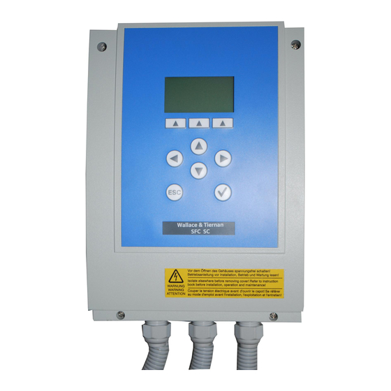
- Page 1 ® WALLACE & TIERNAN MEASURING AND CONTROL SYSTEM Version V:3.08 and later INSTRUCTION MANUAL...
- Page 2 Translation of the original instruction. In some countries, DEPOLOX, OSEC, Barrier, Chem-Ad and Wallace & Tiernan are trademarks of Evoqua, its subsidiaries or affiliated companies. No part of this document may be reproduced in any form (printed, photocopy, microfilm, or any other procedure) or saved, processed, copied, or distributed using electronic data systems - without the express prior written con- sent of Evoqua Water Technologies GmbH.
-
Page 3: Table Of Contents
Contents Contents Introduction ................6 Target groups ......................6 Conventions......................6 Safety..................7 Intended use......................7 General safety instructions ..................7 Warranty conditions....................8 Specific Operating Phases ..................8 Notes on Special Dangers..................8 Description................. 9 Versions........................9 Technical Data ......................9 3.2.1 Electronic module SFC.....................9 3.2.2 Flow block assembly DEPOLOX® 5.................12 3.2.3 VariaSens flow block assembly................14 3.2.4... - Page 4 Contents Outputs ......................... 38 4.3.1 mA output......................38 4.3.2 Relay outputs ......................38 SFC CAN retrofit kit ....................39 Applications ......................40 4.5.1 Application 1 - Process measurement ..............41 4.5.2 Application 2 ......................43 4.5.3 Application 2 - Single feed forward with process measurement......44 4.5.4 Application 2 - Single feedback closed loop control with process measurement 46 4.5.5...
- Page 5 Contents Operation................105 Display and operator controls ................105 Notes on operation .....................108 Menu structure ....................109 Calibration ......................130 6.4.1 Temperature calibration ..................131 6.4.2 3-electrode cell (DEPOLOX® 5 and DEPOLOX® Pool) calibration......131 6.4.3 Membrane sensors calibration................132 6.4.4 pH calibration ......................133 6.4.5 Redox calibration (mV)..................134 6.4.6 Conductivity calibration ..................135 6.4.7...
-
Page 6: Introduction
1. Introduction Introduction CAUTION If this note is not observed, moderate or Target groups minor injury or damage to equipment can result. This instruction manual provides the informa- tion for installation, operating and mainte- nance personnel. It is required for operation CAUTION and maintenance of the unit. -
Page 7: Safety
Furthermore, all inspection and maintenance „Authorized specialists“ are trained technici- work must be performed at the prescribed ans employed by the operator, by Evoqua, or, intervals. if applicable, the service partner. Only quali- The operator bears full and sole responsibility... -
Page 8: Warranty Conditions
If any of the ced parts in accordance with environmen- conditions are not met, the warranty is void. tal regulations! • Installation, commissioning by Evoqua Notes on Special Dangers technicians or trained and authorized spe- cialized personnel, e.g. of contracted com- •... -
Page 9: Description
3. Description Description Version 2 = SFC SC This version only supports application 3 (see 4.5 “Applications”) without the possibility of Versions recording measurements using the sensor There are two versions of the SFC. They differ measuring module. in the type and number of inputs and outputs •... - Page 10 3. Description Operating conditions Ambient temperature 0 – 50 °C Humidity < 80 % Environment Indoor use. No direct sunlight max. altitude 2000 m Atmospheric pressure 75 – 106 kPa Storage temperature -20 – +70 °C Noise emission <45 dB Digital inputs 2x inputs for voltage-free contact (<...
- Page 11 3. Description Relay outputs 4 relay outputs (with Version 1) or 2 relay outputs (with Version 2) (each with two-way switch) Switching values 5 A, 250 V AC, 1250 VA max 5 A, 220 V DC, 150 W max UL/CSA-rating 5 A, 1/6 HP 125, 250 V AC 5 A, 30 V DC, 30 W max 1 A, 30 V DC - 0.24 A, 125 V DC...
-
Page 12: Flow Block Assembly Depolox® 5
3. Description mV measuring Sensor input Redox single rod electrode module for Redox Temperature drift max. 0.2% / 10k Linearity error < 0,1 % Calibration Pre-calibrated Input signal -1000 – +1000 mV Input impedance mS measuring Sensor input LF325 module for Temperature measuring 0 –... - Page 13 3. Description Multi sensor Cable length 650 mm Electrolyte Potassium chloride solution, 3 mol Zero point calibration by stopping flow rate or dechlorinated sample water typ. zero current approx. 1 µA Response time T < 20 sec. Temperature compensation 0 – 50 °C Storage temperature -10°C –...
-
Page 14: Variasens Flow Block Assembly
3. Description 3.2.3 VariaSens flow block assembly Housing Dimensions (WxHxD) 215 x 375 x 155 mm Weight approx. 1.5 kg Connections Sample water PVC hose 6 x 3 mm or PE hose 6 x 1 mm Thread connection G1/2“ or NPT 1/4“ Flow control valve Flow rate approx. -
Page 15: Electrodes
3. Description 3.2.6 Electrodes DES 3-electrode chlo- Measuring system 3-electrode sensor with additional stock rine measuring cell of electrolyte salt (glass electrode) for Principle of operation Potentiostatic amperometry DEPOLOX® Pool flow Temperature compensation 0 – 50 °C block assembly Temperature drift max. -
Page 16: Membrane Sensors
3. Description 3.2.7 Membrane sensors NOTICE Technical data Please refer to the separate instruction manual of the membrane sensors "Free Chlorine FC2", "Total Chlorine TC3", "Chlorine Dioxide CD10.1" and "Ozone OZ10.1". Maximum allowable 0.5 bar (7.25 PSI) only with a suitable flow cell! operating pressure No pressure impulses and/or vibrations. - Page 17 3. Description Connections Power supply + Connecting cable with 5-pin M12 plug CAN bus and 5-pin M12 socket for CAN bus terminal plug or to connect other CAN bus components: M12 socket M12 plug Pin 1 screen Pin 2 +24V Pin 3 Pin 4 CAN high...
-
Page 18: Scope Of Supply
3. Description Scope of supply • CAN sensor measurement module SiDiSens DES NOTICE NOTICE You will find the order numbers under 8. • All retrofit kits or sensor measurement “Complete Units, Retrofit Kits and Spare modules, except for the SiDiSens measu- Parts”. - Page 19 3. Description Overview...
- Page 20 3. Description Free chlorine, ClO 3-electrode measuring cell KMnO Membrane sensor FC1/ Membrane- 1x (only FC2, TC1/TC3, CD7/ covered electrode OZ10.1 CD10.1 or OZ7/OZ10.1 CD10.1) pH 0 – 12 1/2) Redox value -1000 – 1/2) +1,000mV Fluoride 0,20 – 20,00 Conductivity 0,1 –...
-
Page 21: Design
3. Description 3.4.2 Design The electronic module SFC consists of a plastic housing (E) with a removable cover. The hou- The SFC unit has a modular structure and can sing contains: be equipped with various types of sensor mea- suring modules. Several SFC modules can be •... - Page 22 3. Description The following are integrated into the cover: Flow block assembly DEPOLOX® 5 non-pres- surized version • Front panel board with graphic display (B) and interface connections • Insertable strips (C) • SD memory card (D) Fig. 5 Flow block assembly DEPOLOX® 5 cut- away model Fig.
- Page 23 3. Description Flow block assembly VariaSens non-pressu- Flow block assembly DEPOLOX® Pool non- rized version pressurized version Fig. 6 Flow block assembly VariaSens cut- Fig. 7 Flow block assembly DEPOLOX® Pool away model cutaway model A Cell body with cover A Cell body with cover B Plastic housing B Plastic housing...
- Page 24 3. Description Sensor measuring module The sensor measuring module consists of: • Sensor (not with 3-electrode cell DEPO- LOX® 5, mA/V input) • the sensor cable with water-tight housing duct (not with 3-electrode cell DEPOLOX® 5, mA/V input) • Pre-calibrated plug-in card Due to the modular design, simple installation and configuration of sensor measuring modu- les in accordance with the plug-and-play prin-...
-
Page 25: Functions
4. Functions Functions The integrated graphic display displays the fol- lowing: • Measured values General • Mode The SFC is a special measuring and control • Bar graph with limit values device for use in the treatment of potable • Setpoint and measuring range water, industrial process water and pool water. - Page 26 4. Functions The value of the combined chlorine is calcula- Safety functions ted from the difference between the total The following safety functions are integrated chlorine and the free chlorine (optional). This into the control if configured accordingly: requires a free chlorine and total chlorine •...
-
Page 27: Measurement Inputs
4. Functions Flow block assembly DEPOLOX® 5/Varia- When the unit is switched on, the menus are Sens/DEPOLOX® Pool initialized according to the installed sensor These flow block assemblies guarantee a sta- module. Even if the sensor modules are chan- ble measurement signal with: ged at a later date, the user menus are auto- •... - Page 28 4. Functions Mode of operation of the 3-electrode sensor Single-rod 3-electrode sensor for the DEPO- in the flow block assembly DEPOLOX® 5 LOX® Pool for measuring free chlorine The measuring cell in the flow block assembly The disinfection of pool water is carried out DEPOLOX®...
- Page 29 4. Functions Setting guideline Installation notes - Ambient conditions The difference between the µA cell current at The following must be taken into account 0% disinfectant (or sample water stop) and the when installing the 3-electrode measurement: maximum measured value must be within the •...
-
Page 30: Ph Measurement
4. Functions 4.2.2 pH measurement • If the pH electrode is not installed right next to the SFC, extension cables with The pH value is a measured variable in the field plug connectors are available (see 8. of water treatment. It is a measure of the level “Complete Units, Retrofit Kits and Spare of acidity or basicity of a water sample. -
Page 31: Redox Measurement
4. Functions 4.2.3 Redox Measurement Installation notes - Ambient conditions The following must be taken into account The Redox voltage is a measured variable in when installing the Redox measurement: the field of water treatment. The electrical potential present during the Redox reaction is •... -
Page 32: Fluoride Measurement - Fluoride Electrode W2T840142
4. Functions 4.2.4 Fluoride Measurement - Fluoride • The electrode must be immersed at least electrode W2T840142 2 cm deep into the sample water. NOTICE NOTICE No water carrying lines made of copper The fluoride electrode W3T169303 (previos piping may be installed. These would distort version) has been replaced by the fluoride the measurements. -
Page 33: Fluoride Measurement - Fluoride Electrode W3T169303
4. Functions 4.2.5 Fluoride Measurement - Fluoride The electrode can be installed in the flow electrode W3T169303 block assemblies DEPOLOX® 5/DEPOLOX® Pool/VariaSens or in a separate Y-style flow NOTICE through assembly. The fluoride electrode W3T169303 (previos Installation notes - Ambient conditions version) has been replaced by the fluoride The following must be taken into account electrode W2T840142. - Page 34 4. Functions Preparing the electrodes Screw the injection cap on the bottle with the fill solution. Pour a little fill solution into the filling hole. Then rinse the electrode to wet the electrode body O-ring. Press on the electrode cap until the elec- trode body is loosened slightly from the epoxy cover so that the cone is also wet.
-
Page 35: Conductivity Measurement
4. Functions 4.2.6 Conductivity Measurement Installation notes - Ambient conditions The following must be taken into account The conductivity measurement represents a when installing the conductivity measure- composite parameter for the total mineraliza- ment: tion of water. This measurement depends hea- vily on the temperature, therefore a •... -
Page 36: Sensor Measuring Module - Membrane Sensors
4. Functions 4.2.7 Sensor measuring module - Installation notes - Ambient conditions membrane sensors The following must be taken into account when installing the membrane sensors: The following alarm messages are configura- ble: • Select the sample water extraction point that guarantees a proper mixture of disin- •... -
Page 37: Ma/V Input Module
4. Functions 4.2.8 mA/V input module 4.2.11 CAN sensor measurement module SiDiSens The mA/V input module is used for connecting sensors or external measurements with mA or SiDiSens is an external CAN bus component voltage output signal. 0/4 – 20 mA signal or 0 – which can be used to add a measurement 10 V input voltage are possible. -
Page 38: Outputs
4. Functions The SiDiSens is designed as a wall mounting If free chlorine measurement is enabled in ® module. Using an optionally available assem- SFC, a measurement cell DEPOLOX 5 is availa- bly set it can also be fixed to a top-hat rail. ble and a SiDiSens pH is connected via the CAN interface, the Cl ++ measurement is automati-... -
Page 39: Sfc Can Retrofit Kit
4. Functions SFC CAN retrofit kit Connection of small loads When connecting small loads to the mains vol- A retrofit kit with CAN bus socket (M12, 5-pin) tage, e.g. contactors or positioners with low and connecting cable is available as an acces- power consumption (e.g. -
Page 40: Applications
4. Functions Applications The connections are determined by selecting the applications 1, 2 or 3. Factory settings are The configuration of the system is determined always set for the respective application. However, these can be customized to the • Version of the SFC respective system. -
Page 41: Application 1 - Process Measurement
4. Functions 4.5.1 Application 1 - Process measurement With application 1, the SFC operates exclusi- by the type of the sensor measuring module. vely as a measuring device. A maximum of Controller outputs are not supported in this four freely configurable alarm relays are avai- application. - Page 42 4. Functions Fig. 9 shows a sample implementation of The measured value can be forwarded via mA application 1 as individual process measure- signal or CAN bus to a higher-level controller. ment. S e n s o r s 4 x A l a r m r e l a y e a s .
-
Page 43: Application 2
4. Functions 4.5.2 Application 2 • Sensor measuring module without „Pro- cess Control“ option (PC) In application 2, the SFC works as a measuring -> Single feedback closed loop control device and as a control device. Various cont- • Sensor measuring module with „Process roller modes can be selected depending on Control“... -
Page 44: Application 2 - Single Feed Forward With Process Measurement
4. Functions 4.5.3 Application 2 - Single feed forward with process measurement This operating mode controls the quantity- A typical application is simple flow-controlled proportional dosing of disinfectants. The sin- potable water chlorination, as shown in the gle feed forward with process measurement is following figure. - Page 45 4. Functions The ratio between control variable and dosing It is possible that a second control variable output is determined by the internal dosing „Measured Value X“ (measured value from factor (control „Dos.Fact.Source“ = internal), module 1) will have a proportional or inverse or it can also be set by an external mA/V input proportional influence on the single feed for- signal (Dos.Fact.Source = external).
-
Page 46: Application 2 - Single Feedback Closed Loop Control With Process Measurement
4. Functions 4.5.4 Application 2 - Single feedback closed loop control with process measure- ment This operating mode controls the desired The following figure shows a typical applica- measured variable according to the the provi- tion of a chlorine single feedback closed loop ded setpoint. -
Page 47: Application 2 - Compound Loop With Process Measurement
4. Functions An external setpoint from 0 – 100 % can be The controller output is calculated in this ope- provided via the mA/V input signal ("Setpoint rating mode as follows: Source" = external). You can switch between Yout = Ypi = ek x Kp x (1 + t/tn) internal and external setpoint via the digital input ("Setpoint Source"... - Page 48 4. Functions How the combi control works The control direction can be selected with the The compound loop outputs a dosing capacity parameter "Control Direction" = direct or proportional to the flow rate, which does not inverse (e.g. direct = chlorination, inverse = have a fixed dosing factor proportional to the dechlorination) flow rate as in the single feed forward, but...
- Page 49 4. Functions Special Functions • Control variable Wq available optionally • The control direction can be switched. as proportional or indirect proportional as • Automatic determination of the control well as factor adjustment parameter using the integrated fuzzy • Smooth switch from compound loop to module.
- Page 50 4. Functions Calculating the measuring dead time water line and the flow rate to the measuring Calculation 1: cell. With the DEPOLOX® 5 measuring cell, a The sample water is extracted right after the flow rate of 36 l/h is assumed. mixture loop and fed to the measuring cell.
- Page 51 4. Functions Determining the dosing dead time (dosing delay) Dosing dead times arise from long dosing lines and positioner running times. Calculation 1: Determining the dead time based on dosing line length The dosing dead time can be determined as follows: = (4.71 x d ) : Q (result in min)
-
Page 52: Application 3 - Single Feed Forward Without Process Measurement
4. Functions 4.5.6 Application 3 - Single feed forward without process measurement In application 3, the SFC operates exclusively The dosing capacity of the connected device is as a single feed forward. The installation of a controlled automatically, depending on a sensor measuring module is not supported in measuring signal (external flow rate control this application. - Page 53 4. Functions R a t i o c o n t r o l e a s . 1 1 2 : 3 5 4 5 . 6 1 0 0 . 0 0 . 0 0 . 0 M E N U C A L 2 x r e l a y o u t p u t f o r d o s i n g o u t p u t E S C...
-
Page 54: Controller Outputs
4. Functions The figure below shows the output dosing capacity depending on the flow rate Wq and the set dosing factor. Y o u t d o s i n g f a c t o r D i = 2 0 0 % d o s i n g f a c t o r D i = 1 0 0 % 1 0 0 % d o s i n g f a c t o r D i = 5 0 %... - Page 55 4. Functions 2-point pulse duration controller for dosing 3-point pulse-duration controller for dosing pumps pump and 3-point pulse-frequency controller The dosing pump is switched on for the calcu- for pulse pump lated time within an adjustable cycle period TP O u t p u t s i g n a l (relay contact).
-
Page 56: Control Parameters
4. Functions Control parameters Analog output controller 2-point With a controller output of 0 %, the output Control parameters are input variables that current is 0 or 4 mA; with a higher controller determine the control functions of a control- output, the output current reaches up to ler. - Page 57 4. Functions Max.lin.Corr Control direction This parameter monitors changes to already Meaning: Direction of the control learned dosing factors. Display: Direct/inverse (e.g. for pH) If new dosing factor changes are learned, which are larger than the max. linearity cor- Explanation: Defines which medium is used to rection, this dosing factor is used for all values perform the correction.
- Page 58 4. Functions Meaning: Integral action time (I-element) Meaning: Loop rise time Display: Minutes (min) Display: Minutes (min) Explanation: On the basis of the integral action Explanation: Time required to reach the mea- time Tn, the dosing capacity changes cons- suring range end value with 100% dosing che- tantly until the setpoint is reached.
- Page 59 4. Functions Meaning: Running time of the positioner Meaning: Neutral zone Display: Seconds (s) Display: Percentage (%) Explanation: The parameter Ty only applies to Explanation: positioners. The parameter Xsh only applies to 3-point con- trollers. Ty is the time which the positioner requires to adjust from 0 % to 100 %.
-
Page 60: Alarms
4. Functions Alarms Ymin Meaning: Dosing rate basic load The output of the alarms takes place by means (single feedback control-loop control only) of relay contacts and alarm indicators on the Display: Percentage (%) display. The number of the max. four alarms is determined in the application or by the ver- Explanation: The parameter Yminonly applies sion of SFC. - Page 61 4. Functions Unlatched alarm without acknowledgement option (N.O. unlatched, N.C. unlatched) The alarm symbol on the display is on when an alarm is triggered and goes out automatically when the alarm condition is removed. The same applies to the contact. M I N R e l a y w i t h o u t d e l a y...
- Page 62 4. Functions Latched alarm with confirmation (N.O. latched. ack, N.C. latched. ack) In the event of an alarm, the alarm symbol on the display flashes until the alarm is acknowled- ged. • If the alarm condition is no longer present •...
-
Page 63: Adaption
4. Functions Adaption This only applies with Cl single feedback closed loop control. m g / l C l m e a s u r e m e n t 2x setpoint 1 0 0 % setpoint 5 0 % appr. - Page 64 4. Functions u t o - T u n e 0 1 m i n 0 0 s e c 0 0 h 1 0 m i n 0 0 s e c B A C K A D A P T E N T E R A D A P T 2 8 .
- Page 65 4. Functions Adaption sequence Each adaption phase is then displayed with a status message: Display text Explanation " Init“ Start " Ym = 0 %“ Chlorinator to 0 % or dosing pump off " X = 20 %“ Delay until actual value < 0.2 x 2x setpoint "...
-
Page 66: Sample Water Inlet Disinfection
4. Functions If any of the error conditions described above CAUTION occur, adaption is interrupted. The measuring Risk of injury or damage to the system! amplifier displays a fault message. The "old" The remaining control parameters Ymin, parameters Xp and Tn are not changed. Ymax and Tp are not influenced when adap- Determination of the control parameters tion is performed. - Page 67 4. Functions K r e i s 0 , 0 0 1 . 0 0 0 . 4 3 m g / l 0 , 0 0 M E N U C A L E S C disinfectant tank sample water This function can be found on the main "Extern.
- Page 68 4. Functions The disinfection process is shown schematically below:...
-
Page 69: Serial Interfaces
Matching RS232 con- • As soon as the "Delay" has finished, the nection cable: part no. W3T164902). -
Page 70: Can Interface
4. Functions 4.12 CAN interface The SFC operates as a master in the bus sys- tem. CAN slaves are the attached sensors. The CAN interface is used as a CAN sensor bus and serves to connect: NOTICE There can only be one master in the CAN bus •... - Page 71 4. Functions In each case on the first and last device on the The SiDiSens is supplied with a special plug for bus a bus terminator (bus end Rt) must be the bus termination which can be plugged installed. directly into the free connection socket for ter- mination.
-
Page 72: Fieldbus
1.02. The latest software can be downloa- ded from the download area of the Internet The SFC offers two different ways to perform a homepage at www.evoqua.com. firmware update. Following files are needed for the update: Serial firmware update •... - Page 73 4. Functions Firmware Update Loading Bootloader !! Warning !! Do NOT turn off the device or put out the SD-card during the firmware update! CANCEL To start the update, confirm this display with "OK" key. Check Flash Check Firmware Firmware found: V: 01.06 EAE1057 Install firmware?
-
Page 74: Actuator Feedback
4. Functions 4.15 Actuator feedback Possible signals are: • Potentiometer 1 KOhm The actuator feedback of the SFC is set at the • Potentiometer 5 KOhm factory to potentiometer with 1 kOhm. For • 0/4 – 20 mA signal other feedback signals the device must be •... - Page 75 4. Functions The SD memory card is installed inside the The data can be further processed using any SFC. In order to remove or replace the SD text editor or table processing program, such memory card, the cover of the SFC must be as EXCEL.
-
Page 76: Unit Configuration
4. Functions 4.18 Unit configuration 4.19 Special Features The SFC gives the option of saving all unit set- Temperature measurement tings as a configuration. Unit settings include If there is no temperature measurement integ- all parameters that can be set in the menu, rated into the sensor measuring module (DES), such as the controller mode, setpoint, limit the PT 1000 temperature measurement is... -
Page 77: Installation
5. Installation Installation Opening the housing Remove the housing cover of the flow block assembly. To this purpose, lightly Transport and storage press the two buttons on the top of the Transport housing (optional). The unit is supplied in standard packaging. Release the four screws on the cover of During transport the packaged unit must be the electronic module. - Page 78 5. Installation Installation without mounting rails Control cabinet installation If the electronic module and the flow block A special version is available for control cabi- assembly are to be mounted in different pla- net installation. The base unit (basic electro- ces, the modules can be hooked onto suitable nics) of this version is attached to the tallow-drop screws by the top holding fixtures...
- Page 79 5. Installation Top-hat rail assembly...
- Page 80 5. Installation Top-hat rail assembly...
- Page 81 5. Installation Wall mounting assembly...
- Page 82 5. Installation Wall mounting assembly...
- Page 83 5. Installation Control cabinet installation assembly...
- Page 84 5. Installation Control cabinet installation assembly...
- Page 85 5. Installation Installation of the front panel on the control cabinet...
- Page 86 5. Installation Installation of the front panel on the control cabinet...
-
Page 87: Commissioning
5. Installation Commissioning Completion of each task can be confirmed in the "Completed" column. 5.3.1 Installation guide NOTICE Commissioning procedure If this installation sequence cannot be com- When the unit has been mounted, the sensor plied with, please contact your contractual measuring module can be equipped (not partner. - Page 88 5. Installation Seq. Chapter and page Com- Task reference pleted Set module descriptions page 121 Select control mode page 121 Set dosing output, and adjust positioner running page 121 time, Tp, and max. pulses if necessary On positioner with feedback calibrate„Ym”. page 121 With feedback signals, such as mA signal, 0 –...
-
Page 89: Pour In The Cell Sand (Only With Depolox® 5 And Depolox® Pool)
5. Installation Seq. Chapter and page Com- Task reference pleted Check limit values for external set point/dosing fac- Page 117 tor, adjust if necessary (only if using an external set- point/dosing factor) Check mA signal, adjust if necessary (only if mA Page 117 output is used) Check mA allocation, adjust if necessary (only if mA... -
Page 90: Inserting And Connecting Sensors
5. Installation 5.3.3 Inserting and Connecting Sensors CAUTION Risk of injury or damage to the system! Install the membrane sensors into the flow cell module. The maximum allowable operating pressure of the membrane sensors is 0.5 bar (7.25 PSI)! With the pressurized version, the membrane sensor must be screwed in or secured to prevent them from beeing pushed out. - Page 91 5. Installation Abb. 6 DEPOLOX® Pool, non- Abb. 7 DEPOLOX® Pool, Abb. 8 DEPOLOX® Pool, pressurized version pressurized version pressurized version with cell body cover W3T417269 (optional) A Membrane sensor: FC1/FC2, CD7/CD10.1, OZ7/OZ10.1, TC1/TC3 B Redox Conductivity D pH 3-electrode sensor (single rod glass electrode) Plug Remove the protection caps from the sen- NOTICE...
- Page 92 5. Installation Arrangement of the plug-in cards and cables Connecting the sensor cables Place the sensor cables with the attached bushes into the cable ducts of the housing. Depending on the sensor design, either plug or screw the cable in place. Insert the supplied bushes into ducts that are not in use in order to seal the housing.
-
Page 93: Replace Standard Cell Body Cover (Optional)
5. Installation 5.3.4 Replace standard cell body cover 5.3.5 Connecting the sample water and ® DEPOLOX (optional) starting up, taking as an example The pressurized version DEPOLOX® 5 and DEPOLOX® Pool can be retrofitted with a mem- brane sensor. Please note that the standard cell body cover must be replace by an optional cell body cover (W3T417351 - DEPOLOX®... - Page 94 5. Installation Non-pressurized version Remove felt ring Remove the transport plug (yellow) from NOTICE the electrolyte storage tank and replace To keep the diaphragm moist and prevent with the stopper. crystallization in the filled electrodes there is a damp felt ring in the gap between the membrane and the electrodes when the unit is in storage.
- Page 95 5. Installation Connecting the sample water inlet Push the locking ring out until the union nut engages the connecting threads. NOTICE Never use copper tubing. The pressure in the sample water inlet must always be within a range of min. 0.2 to max.
- Page 96 5. Installation Connecting the sample water outlet With hose connection See installation instructions page 95. NOTICE With rigid pipework Never use copper tubing. Connect the sample water pipework to On the non-pressurized version, no back- the connection nozzle. pressure is permitted in the cell body. The Ensure that the sample water pipework is sample water outlet must be open.
- Page 97 5. Installation Examples for sample water extraction with booster pump Example 1...
- Page 98 5. Installation Example 2...
-
Page 99: Fitting The Fine Filter
5. Installation Parts list 5.3.6 Fitting the fine filter Sample water extraction for fresh water part Insert fine filter with the flow through adap- no. W3T158528 ters DEPOLOX® 5, VariaSens and DEPOLOX® Pool. Sample water extraction for salt water part no. W3T158529 NOTICE •... -
Page 100: Connect The Device To The Power Supply
5. Installation 5.3.7 Connect the device to the power CAUTION supply Risk of injury or damage to the system! WARNING • To ensure safe and correct commissio- ning, knowledge of the operation, con- Risk of injury or damage to the nected electrical load, measurement system! signals, cable assignment and fuse pro-... -
Page 101: Mounting The Housing Covers
5. Installation 5.3.9 Mounting the housing covers tion. When the country language is set, this screen is no longer shown. Ensure that the cable bushes are fitted correctly. P l e a s e s e l e c t Carefully fit the housing cover of the elec- l a n g u a g e ! L a n g u a g e... -
Page 102: Positioner Calibration With Compound-Loop-Control And Single Feed Back Control
5. Installation Press the APPLIC softkey. Manual calibration The "Application Select" menu then appe- Starting with the basic display, open the ars. „Actuator“ window from the „Module Confirm the selection with the "ENTER" Type“ menu. softkey. Select and confirm the parameter „Ym Another application can be chosen using Calibration Manual“. -
Page 103: Positioner Calibration With Sfc (Application 3) Or Single Feed Forward (Application 2)
5. Installation 5.3.13 Positioner calibration with SFC • The calibration points can be selected (application 3) or single feed using the up/down arrow keys. Press forward (application 2) Enter to calibrate the support points, and use the up/down arrow keys to open/ In these applications the linearization of the close the positioner until the actual control output is possible, such as for example... -
Page 104: System Shut Down
5. Installation System shut down Store the sensors in a frost-free place. NOTICE CAUTION The water must be drained if frost occurs. Risk of injury or damage to the system! Insert electrode in a beaker with water and • Risk of uncontrolled dosing of chlorine store in a frost-free or pH-correction medium! Shut down place. -
Page 105: Operation
6. Operation Operation Indicators Symbols Meaning Display and operator controls CONTROL 1 System name (Enter in All information is shown on the graphic display menu „System“ - „Com- with backlight. mon“ - „System name“) The backlight of the display becomes brighter Digital inputs 1, 2 active The symbols indicate that a at the touch of a key. - Page 106 6. Operation Softkey Meaning Symbols Meaning 100% If the display blinks, the "Adaption" operating mode positioner is in manual active during "Manual" ope- mode and cannot be activa- ration ted. Automatic determination of the control parameters for 28.4°C Sample water temperature the single feedback closed- Error indication active (dis- loop controller is active.
- Page 107 6. Operation General messages NOTICE Information about what plug-in card is con- Adaption is currently running! tained in the device is displayed in the "Ana- This message appears if an attempt is made log scan" when the device is switched on or during adaption to automatically calibrate the can be viewed statically in the "Diagnosis"...
-
Page 108: Notes On Operation
6. Operation Notes on operation Each password comprises a four-digit number combination. During operation observe the following points: NOTICE • The password is not set at the works • Check your entries and modifications (four zeros). before exiting the menu. •... -
Page 109: Menu Structure
6. Operation Menu structure The following pages show the eight individual menus. The displays contain the settings made The SFC has various manus: at the works. • Main menu • Module type, e.g. Cl free 1 NOTICE • Extern. Functions The actual displays on your unit may vary •... - Page 110 6. Operation Main menu Basic display 1 - Top status line • System name 1 2 : 2 0 A n a l y s e r 1 m g / l • Digital inputs activated 0 , 1 5 •...
- Page 111 6. Operation Menu - Module type (Display based on a free chlorine measurement example) E S C 1 2 : 2 0 A n a l y s e r 1 B A C K m g / l 0 , 1 5 c a l i b r a t i o n 0 0 0 % 0 0 0 , 0 %...
- Page 112 6. Operation Actuator Control out- El.Pos.w.Ym L i m i t v a l u e s M i n I Electr.Pos.wo.Ym 0 , 3 0 m g / l Dosing pump 2P. M a x I 0 , 6 0 m g / l Dosing pump 3P.
- Page 113 6. Operation Parameter Adjustment of the measuring range: 0,0 – 5,0 % 100 / 200 / 500 µg/l 1.00 / 2.00 / 5.00 / 10.0 / Tkonst 30 s – 10 min 20.0 / 50.0 / 100 / 200 mg/l Tvar 30 s –...
- Page 114 6. Operation Sensor name: Factor: mA/V Setting of a customer-specific sensor name, Factor for adapting an external input signal: for example, "KMNO " with a maximum of 0.1 – 4.0 seven definable characters. Format: Reference temp.: mA/V Selection of the displayed number format for Adjustment of the reference temperature for mA/V sensor modules: 000.0 / 00.00 / 0000 the conductivity measurement: 20°C / 25°C...
- Page 115 6. Operation Limit value 2 Setup Min You/Ym 0 – 100.0 % (not with single Control direct direct/inverse feedback closed loop cont- rol) Max Yout/Ym 0 – 100.0 % (not with single Measuring range feedback closed loop cont- rol) Range start: Ym is only output when posi- tioner feedback is available, otherwise the controller out-...
- Page 116 6. Operation Menu - Extern. Functions (This function is only available with DES modules.) Basic display 1 2 : 2 0 A n a l y s e r 1 Refer to main menu m g / l 0 , 1 5 C l 2 f r e e T a n k...
- Page 117 6. Operation Menu - Inputs/Outputs 1 2 : 2 0 A n a l y s e r 1 m g / l 0 , 1 5 e x t . S e t p o i n t / D S i g n a l C l 2 f r e e 0 .
- Page 118 6. Operation Flow rate Digital input Signal 0 – 20 mA, 4 – 20 mA DI (1), DI (2) Every digital input can be assigned a function. Factor 0,1 – 4,0 SW-LOSS FCT Yout = 0 %, dosing, mA conti- Format Measurement display 000.0 (only with DI...
- Page 119 6. Operation Menu - Alarm 1 2 : 2 0 A n a l y s e r 1 l a r m 1 - 4 a s s i g n m g / l 0 , 1 5 A l a r m M I N M A X...
- Page 120 6. Operation Alarm 3/4 funct Alarm assign. 1/2/3/4 This parameter gives the option of defining Alarm 3 func- See description of alarm 1 the switching conditions for the alarms: tion • Min I and Max I of the measurement of Alarm 3 delay See description of alarm 1 the sensor module Alarm 4 func-...
- Page 121 6. Operation Menu - System o n f i g u r a t i o n 1 2 : 2 0 A n a l y s e r 1 S a v e m g / l 0 , 1 5 J o b 1 R e s t o r e C l 2...
- Page 122 6. Operation NOTICE • At increasing lifespan the backlight y s t e m e s e t S y s t e m r e s t a r t brightness drops. The backlight bright- ness can be adapted to the respective D e l e t e d i a g r a m ambient conditions or to other systems.
- Page 123 6. Operation Safety System reset 00:00 – 10:00 (03min : 00s) System yes/no feed delay Restart Samp. water 00:00 – 10:00 (01min : 00s) (sample water delay) Delete yes/no delay graph System pass- four-digit numeric code word (activate with softkey Standard yes/no "LOCK"...
- Page 124 6. Operation Menu - Diagnosis ( 5 ) 1 2 : 2 0 A n a l y s e r 1 l a s t 5 c a l i b r a t i o n d a t a s m g / l 0 , 1 5 o s i n g...
- Page 125 6. Operation Calibration data of 3-electrodesensor for Cl B A C K - - > KMnO , ClO , Cl i a g n o s t . D o s i n g f a c t o r Calibration data with date and time of the last 1 0 0 5 calibrations (1-5)
- Page 126 6. Operation Conductivity calibration data Third display - Inputs/Outputs Date and time of the last 5 calibrations Information on: • Measured value module Span Calibration factor of the con- • compound loop Yout in % ductivity measuring cell • Ypi-share of Yout in % act.
- Page 127 6. Operation Menu - Calibration (refer to 6.4 “Calibration”) 1 2 : 2 0 A n a l y s e r 1 m g / l 0 , 1 5 C l 2 f r e e a l i b . T e m p e r a t u r e E S C c a l i b .
- Page 128 6. Operation Module type calibration Conductivity mA/V input calibration Calib 0 – 200 mS/cm Cal. zero within measuring range Calib. tempe- 0 – 50 °C Cal. span within measuring range rature Temperature calibration Module type calibration Membrane sensors Calib. tempe- 0 –...
- Page 129 6. Operation Basic display Description of the operating modes: Refer to main menu MANUAL Manual / Automatic Dosing is not automatically controlled in the AUTO / MANUAL MANUAL mode. The values must be continu- toggle using the "CHANGE" softkey ously monitored. Setpoint The MANUAL mode is used: Setting the setpoint or dosing factor (depen-...
-
Page 130: Calibration
6. Operation Calibration Calibration aids of the flow rate module DEPOLOX® 5, DEPOLOX® Pool, VariaSens Sensor measuring module calibration Two clips are installed in the housing cover. These clips can be inserted into the rear panel CAUTION of the housing. The clip (A) for the sensor will With the pressurized version, when calibrat- be inserted into the upper catch. -
Page 131: Temperature Calibration
6. Operation 6.4.1 Temperature calibration Close the ball valve on the sample water inlet. Starting from the basic display in the main menu select the "Calibration" menu. NOTICE Select the "Temperature" menu item. The When the sample water supply has been window "Calib. -
Page 132: Membrane Sensors Calibration
6. Operation 15 Use the arrow keys to enter the determi- Total chlorine ned value. Finally save by pressing In the calibration of the total chlorine measu- "Enter". Should the measured sensor rement, the free chlorine value is also essen- value (µA) according to step 12 have tial. -
Page 133: Ph Calibration
6. Operation Immediately after this extract specimen Select the measurement to be calibrated of sample water and determine the com- from the menu and confirm with „Enter“. bined or total chlorine content using a Select the parameter „Calib. span“ and comparative device. -
Page 134: Redox Calibration (Mv)
6. Operation Slope alignment 6.4.5 Redox calibration (mV) 10 Remove the buffer solution pH 7.00 from NOTICE the bottom fastening clip. Redox sensors have long running-in times. 11 Wash the sensor in distilled water to pre- After calibration with a buffer solution, it can vent carry-over of the buffer solution. -
Page 135: Conductivity Calibration
6. Operation 6.4.6 Conductivity calibration 6.4.7 Fluoride calibration The fluoride measurement is calibrated at 2 NOTICE points, which should be as far from each other The conductivity sensor has an integrated as possible, but within the measurement temperature sensor and therefore an auto- range. - Page 136 6. Operation Fluoride correction Confirm the selection with „Enter“ and If external influences result in a constant diffe- using the four arrow keys enter the diffe- rence between the displayed value and a fluo- rence between the comparative value and ride value measured manually, this difference the displayed value (comparative value can be compensated:...
-
Page 137: Errors And Remedies
6. Operation Errors and remedies 6.5.1 Error messages The following table shows and explains all possible error messages which can be displayed. If seve- ral errors occur at the same time, the corresponding messages appear alternately in succession. When the error has been remedied, the error message is automatically deleted. NOTICE If you are unable to remedy the error yourself, please contact your contractual partner. - Page 138 6. Operation Error message Cause Remedy Calibration? In 3-electrode cells and membrane Check whether there are air bub- sensors bles on the membrane sensor and Slope error - the sensor current remove, if necessary based on 1 mg/l has fallen below Service membrane sensors - replace the required minimum electrolyte/membrane cap...
- Page 139 6. Operation Error message Cause Remedy Cell ? In 3-electrode cells Screw in sensor correctly. Chlorine sensor not screwed in. Check grit cleaning. No grit cleaning. Sensor, sensor cable or sensor Check sensor, sensor cable or sen- module defective. sor module, replace if necessary. Sensor measuring module µA mea- Select higher µA measuring range suring range exceeded...
-
Page 140: Error
6. Operation 6.5.2 Error The following table shows and explains possible errors which can occur. NOTICE If you are unable to remedy the error yourself, please contact your contractual partner. Error Cause Remedy No indication on No power supply External switch or fuse on device Device fuse defective Check the power supply and replace... -
Page 141: Maintenance
7. Maintenance Maintenance Maintenance Schedules NOTICE The liability for defects is only valid if maintenance work is performed as specified. Adhere to the appropriate standards, regulations and locally applicable guidelines. Activity Period/Interval Page Flow block assembly DEPOLOX® 5/DEPOLOX® Pool/VariaSens Check for leakages Daily page 142 Comparative measurement, calibrate if neces-... -
Page 142: Checking For Tightness (Daily)
7. Maintenance Checking for tightness (daily) Close the drain valve when the cell body is empty. Check the entire measuring device including Remove the sensors. Remove sensor all screw connections for leakage. Repair any cable from the sensors. leakage points immediately! Loosen the lower cap on the 3-electrode cell (DEPOLOX®... -
Page 143: Check Electrolyte Level Of The 3-Electrode Cell Depolox® 5
7. Maintenance 18 Perform the zero-point calibration after Replacing electrolyte, reference electrode approximately three hours running-in and diaphragms (DEPOLOX® 5) time. Remove cover of flow block assembly DEPOLOX® 5. NOTICE Close the ball valve on the sample water • You must calibrate each time the cell inlet and on the outlet (pressurized ver- sand is replaced. - Page 144 7. Maintenance Replacing diaphragms (DEPOLOX® 5) 22 Reconnect the signal cable acc. to color. CNT Counter Blue point Blue cable NOTICE electrode The diaphragms, which form the contact WRK Working Red point Pink cable between the reference electrodes and sam- electrode ple water, cannot be cleaned.
-
Page 145: Maintaining Membrane Sensors
7. Maintenance Cleaning/replacing the fine filter Rinse the fine filter with water, replace if (DEPOLOX® 5, DEPOLOX® Pool, VariaSens) necessary. Place the fine filter into the filter unit. NOTICE Ensure that the O-ring is fitted correctly • A fine filter must only be installed when (insert as far as possible). -
Page 146: Maintaining Ph Electrode
7. Maintenance Maintaining pH electrode Maintaining fluoride electrode Clean and calibrate if there are fluctuations in Routinely calibrate the measuring system to the measured values. A routine schedule can- guarantee safe operation and accuracy. not be given here because the cleaning sche- The electrode shaft can be cleaned using a dule depends heavily on the general condition moist cloth. -
Page 147: Changing The Fuse On The A&C Board
7. Maintenance 7.10 Changing the fuse on the A&C 7.11 Replacing the battery board WARNING WARNING Risk of injury or damage to the device! Risk of injury or damage to the • Only authorized and qualified device! electricians are permitted to open •... -
Page 148: Complete Units, Retrofit Kits And Spare Parts
8. Complete Units, Retrofit Kits and Spare Parts Complete Units, Retrofit Kits and Spare Parts NOTICE For reasons of safety, only use original spare parts. Please contact our customer service department if you need any spare parts. Part No. Complete unit W3T158815 SFC Electronic 100 –... - Page 149 8. Complete Units, Retrofit Kits and Spare Parts Sensor measuring modules Redox Conductivity Conductivity Fluoride potable water pool water incl. calibration incl. calibration incl. 600 µS cali- incl. 60 mS cali- incl. sensor, solution, sensor, solution, sensor, bration solution, bration solution, cable, plug-in cable, plug-in cable, plug-in...
- Page 150 8. Complete Units, Retrofit Kits and Spare Parts Retrofit sets 3-electrode cell 3-electrode cell 3-electrode cell 3-electrode cell mA/V input card DEPOLOX® 5 DEPOLOX® 4 Micro 2000 with DEOX 2000 with with PT100 PT1000 PT1000 Plug-in card with Plug-in card with Plug-in card with Plug-in card with Plug-in card with...
- Page 151 8. Complete Units, Retrofit Kits and Spare Parts Spare parts and consumables DEPOLOX® 5 Redox Conductivity Fluoride Fluoride DEPOLOX® 4 DEPOLOX® W3T169303 W2T840142 Pool Sensor Sensor Sensor Sensor Glass W3T169297 W3T169298 W3T172052 W2T840142 electrode W3T172052 Multi sensor Calibration Calibration Calibration Calibration Electrode W3T172029...
- Page 152 8. Complete Units, Retrofit Kits and Spare Parts Membrane sensors Membrane sensors Free chlorine Ozone Total chlorine OZ10.1 CD10.1 Sensor compl. with electrolyte, W3T365498 W3T517687 W3T541984 W3T391561 lapping paper Membrane cap W3T365500 W3T517688 W3T517688 W3T365500 Membrane cap with memb- W3T391564* W3T391564* rane disk holder made of plas- tic*...
- Page 153 8. Complete Units, Retrofit Kits and Spare Parts SFC spare parts Part No. Designation W3T166455 Spare circuit board A&C board SFC 100 – 240 V AC W3T166456 Spare circuit board A&C board SFC 24 V DC W3T166457 Spare circuit board A&C board SFCSC 100 – 240 V AC W3T166458 Spare circuit board A&C board SFCSC 24 V DC W3T162628...
- Page 154 8. Complete Units, Retrofit Kits and Spare Parts Seal set for membrane electrodes Flow rate monitoring with temperature sensor PT1000 Part No. Designation Part No. Designation W3T158755 Seal set for membrane elec- trodes, pressure-tight ver- W3T166494 Flow rate monitoring with sion temperature sensor PT1000 pressurized version up to...
- Page 155 8. Complete Units, Retrofit Kits and Spare Parts Flow-through adapter pH/mV Part No. Designation W3T171332 Flow-through adapter pH/mV, non-pressurized version W3T159950 Flow-through adapter pH/mV, pressurized version up to 6 bar Fig. 3 Flow-through adapter pH/mV Item Part No. Designation W3T172856 Housing W3T170970 (non-pressurized) Electrode mount...
- Page 156 8. Complete Units, Retrofit Kits and Spare Parts Flow-through adapter fluoride Part No. Designation W3T163663 Flow-through adapter fluoride, non-pressurized version Fig. 4 Flow-through adapter fluoride Item Part No. Description W2T505181 PVC screw connection, DN15/d20, with O-ring W2T507048 Ball valve W2T506240 Hose bushing W3T168889 Seal...
- Page 157 8. Complete Units, Retrofit Kits and Spare Parts Flow-through adapter conductivity Part No. Designation W3T158503 Flow-through adapter conductivity, pressurized version up to 6 bar Fig. 5 Flow-through adapter conductivity Pos. Part No. Designation W3T161463 Strainer housing W3T158502 Electrode mount W3T158501 Electrode tightening nut W3T163440 Hesagon cap nut...
- Page 158 8. Complete Units, Retrofit Kits and Spare Parts DEPOLOX® 5 retrofit set (non-pressurized version) - W3T170031...
- Page 159 8. Complete Units, Retrofit Kits and Spare Parts Parts list for DEPOLOX® 5 non-pressurized version - W3T170031 Part No. Designation W3T170031 Flow cell module, non-pressurized W3T322432 Cell body D5-DL, complete W3T166171 Drainage unit W3T158603 Non-return valve W3T163739 Valve seat complete W3T166194 Fine filter W3T166210...
- Page 160 8. Complete Units, Retrofit Kits and Spare Parts Drawing of DEPOLOX® 5 non-pressurized version - W3T170031...
- Page 161 8. Complete Units, Retrofit Kits and Spare Parts Parts list for DEPOLOX® 5 non-pressurized version - W3T170031 Item Part No. Designation Item Part No. Designation W3T169815 Locking ring W3T160628 Basic housing W3T161502 Union nut 1,92, W3T164571 Basic housing, pre- assembled 50-53 W3T171453 Hose connection parts W3T160629 Housing cover W3T158601 Hose...
- Page 162 8. Complete Units, Retrofit Kits and Spare Parts Retrofit set for DEPOLOX® 5 (pressurized version) - W3T170032...
- Page 163 8. Complete Units, Retrofit Kits and Spare Parts Parts list for DEPOLOX® 5 (pressurized version) - W3T170032 Part No. Designation W3T170032 Flow block assembly, pressurized W3T170025 Cell body D5-DF, complete W3T166171 Drainage unit W3T158603 Non-return valve W3T163739 Valve seat complete W3T166194 Fine filter W3T166210...
- Page 164 8. Complete Units, Retrofit Kits and Spare Parts Drawing of DEPOLOX® 5 (pressurized version) - W3T170032...
- Page 165 8. Complete Units, Retrofit Kits and Spare Parts Parts list for DEPOLOX® 5 (pressurized version) - W3T170032 Item Part No. Designation Item Part No. Designation W3T161501 Hose bushing W3T160628 Basic housing W3T169815 Locking ring 1,92,9 W3T164571 Basic housing, pre-assembled W3T161502 Union nut 50-53 W3T171453 Hose connection parts W3T160629 Housing cover W3T172042 Product label...
- Page 166 8. Complete Units, Retrofit Kits and Spare Parts VariaSens retrofit set (non-pressurized version) - W3T158742...
- Page 167 8. Complete Units, Retrofit Kits and Spare Parts VariaSens parts list (non-pressurized version) - W3T158742 Part No. Designation W3T158742 Flow cell module, non-pressurized W3T158744 Cell body VS-DL, complete W3T166171 Drainage unit W3T158603 Non-return valve W3T163739 Valve seat complete W3T166194 Fine filter W3T158747 Flow body complete W3T158746...
- Page 168 8. Complete Units, Retrofit Kits and Spare Parts VariaSens drawing (non-pressurized version) - W3T158742...
- Page 169 8. Complete Units, Retrofit Kits and Spare Parts VariaSens parts list (non-pressurized version) - W3T158742 Item Part No. Designation Item Part No. Designation W3T158575 Drain screw W3T160628 Basic housing W3T166160 EPDM Flat gasket 1,92,9 W3T164571 Basic housing, pre-assembled W3T172556 O-ring W3T160629 Housing cover W3T158738 Cell body cover W3T160908 Product label...
- Page 170 8. Complete Units, Retrofit Kits and Spare Parts VariaSens retrofit set (pressurized version) - W3T158756...
- Page 171 8. Complete Units, Retrofit Kits and Spare Parts VariaSens parts list (pressurized version) -W3T158756 Part No. Designation W3T158756 Flow block assembly, pressurized W3T158759 Cell body VS-DF, complete W3T166171 Drainage unit W3T158603 Non-return valve W3T163739 Valve seat complete W3T166194 Fine filter W3T158747 Flow body complete W3T158767...
- Page 172 8. Complete Units, Retrofit Kits and Spare Parts VariaSens drawing (pressurized version) - W3T158756...
- Page 173 8. Complete Units, Retrofit Kits and Spare Parts VariaSens parts list (pressurized version) - W3T158756 Item Part No. Designation Item Part No. Designation W3T158754 Cell body cover W3T160628 Basic housing W3T160657 O-ring 1,92 W3T164571 Basic housing, pre- assembled W3T172861 O-ring W3T160629 Housing cover W3T161501 Hose bushing W3T160908 Product label...
- Page 174 8. Complete Units, Retrofit Kits and Spare Parts Ready-to-install assembly for DEPOLOX® Pool...
- Page 175 8. Complete Units, Retrofit Kits and Spare Parts Drawing DEPOLOX® Pool non-pressurized version - W3T158598...
- Page 176 8. Complete Units, Retrofit Kits and Spare Parts Parts list DEPOLOX® Pool non-pressurized version - W3T158598 REF: WAE4161 Item Part No. Designation Item Part No. Designation W3T161501 Hose bushing W3T164571 Basic housing, pre-assembled W3T169815 Locking ring W2T507548 Type plate W3T161502 Union nut W3T160629 Housing cover W3T158601 Hose W3T172038 Product label...
- Page 177 8. Complete Units, Retrofit Kits and Spare Parts Drawing of DEPOLOX® Pool pressurized version - W3T158599...
- Page 178 8. Complete Units, Retrofit Kits and Spare Parts Parts list DEPOLOX® Pool non-pressurized version - W3T158599 REF: WAE4162 Item Part No. Designation Item Part No. Designation W3T172861 O-ring W3T164571 Basic housing, pre-assembled W3T161501 Hose bushing W2T507548 Type plate W3T169815 Locking ring W3T160629 Housing cover W3T161502 Union nut W3T172038 Product label...
-
Page 179: Wiring Diagrams
9. Wiring Diagrams Wiring Diagrams WAE7593 Issue 04-0719 A&C-Board Internal board-to-board connection Power via connecting plug mA-Output inside the case optionally terminal strips L2/N +24V DC 15 16 L2/N (M) +24V DC 24V 0/4...20mA Power Load max. 500Ohm L1/N/PE AC 100...240V Wiring via the terminals only required DC 24V if installed in a control cabinet... - Page 180 9. Wiring Diagrams W3T164649 (AAC9049) Connection (sensor) - measurement module W3T158849 (AAD9421) W3T162661 (AAD9394) W3T164933 (AAD9376) W3T162662 (AAD9397) W3T160541 (AAC2695) W3T164930 (AAD9367) W3T158845 (AAD9403) W3T164931 (AAD9370) W3T158848 (AAD9418) 3 pot cells DES membrane cells Redox 3 pot cells + temp. sensor W3T164650 (AAC9052) W3T158850 (AAD9424) Pt100...
- Page 181 9. Wiring Diagrams Connections front panel board (Display board) Internal board-to-board connection via RJ45 connecting plug inside the case optionally terminal strips CAN ext. 3 4 5 10 11 1213 DC 24V 2) W&T RS485-Bus 3) DC 24V Connector internal CAN sensor/actuator bus CAN-front panel/A&C-Board (Only requires wiring if installed in a control cabinet,...
- Page 182 9. Wiring Diagrams Relay-outputs A&C-Board (mother board) (Application 1) 20 21 22 alarm 1 alarm 2 alarm 3 alarm 4 Sample Line dosing Connection from Micro 2000 / Deox 2000 Drive 20 21 22 If the sensor-measuring module for Micro 2000 or Deox 2000 is installed, the Alarm 4 output should be L2/N used to control the drive.
- Page 183 9. Wiring Diagrams Relay-outputs(mother board) (Application 2 + 3) 20 21 22 alarm 1 alarm 2 or Connection Micro 2000 / Sample Line dosing Deox 2000 L2/N External voltage may PE N still be connected even when the main switch is set to OFF ! Positioner 27 28 27 28...
- Page 184 9. Wiring Diagrams Connection of a dosing pump with external enable signal input contact Note: To prevent starting delay we recommend to use L2/N pumps with external enable signal input. In this case connect ext. the enable signal input release directly to the relay contact.
-
Page 185: Declarations And Certificates
10. Declarations and certificates 10. Declarations and certificates... - Page 186 10. Declarations and certificates...
- Page 187 10. Declarations and certificates...
- Page 188 10. Declarations and certificates...
-
Page 189: Settings Table
11. Settings Table 11. Settings Table NOTICE This settings table shows all of the settings available in SFC. Depending on the application selected and the sensor measuring modules fitted, various menu items, menu parameters and setting parameters may be hidden. Cross out any that are not applicable. - Page 190 11. Settings Table Setting parameters Menu Menu parameters Commissioning (factory setting) Measuring range Range start 4.00 400 mV mA/V Range end 9.00 900 mV mA/V 100 % Measuring range 1,00 mg/l 1,0 mg/l 2,00 mg/l 10,00 mS/cm Sensor type Definition of the senosr with 3-electrode cells: free Cl Definition of the senosr...
- Page 191 11. Settings Table Setting parameters Menu Menu parameters Commissioning (factory setting) Limit value 2 Min Yout/Ym 20 % Max Yout/Ym 80 % Hysteresis Min Ypi 20 % Max Ypi 80 % Hysterese 5,0 % Adaption 1min00s 00h10min00s Module type 2 Actuator Control output Dosing pump 2P...
- Page 192 11. Settings Table Setting parameters Menu Menu parameters Commissioning (factory setting) Analog out mA Signal Measured value Digital input DI (1) MW-STOP FCT DI (2) Interface RS485 Adress Alarm Alarm 1 function N.O. unlatched Alarm 1 delay 00h00min00s Alarm 2 function N.O.
- Page 193 11. Settings Table Setting parameters Menu Menu parameters Commissioning (factory setting) Trend Graph Channel 1 Measured value Channel 2 Temperature Module designation Module ---- System reset System restart Delete graph Standard values Delete dos. avg. Dosing factors 50 % Settings changed from: Settings changed on:...
- Page 194 11. Settings Table...
- Page 195 Wallace & Tiernan® Products worldwide Australia Canada China +61 1300 661 809 +1 905 944 2800 +86 21 5118 3777 info.au@evoqua.com wtoe.can@evoqua.com sales.cn@evoqua.com France Germany Singapore +33 1 41 15 92 20 +49 8221 9040 +65 6559 2600 wtfra@evoqua.com wtger@evoqua.com sales.sg@evoqua.com...
- Page 196 © 2021 Evoqua Water Technologies GmbH Subject to modifications WT.050.590.000.DE.IM.1221 W3T168777 Issue 21-1221 Auf der Weide 10, 89312 Günzburg, Deutschland +49 (8221) 904-0 www.evoqua.com...
Need help?
Do you have a question about the WALLACE & TIERNAN SFC and is the answer not in the manual?
Questions and answers