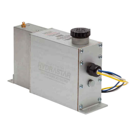
Summary of Contents for Hydrastar HBA-10
- Page 1 MANUAL 440-1008 SERVICE MANUAL FOR HYDRASTAR HYDRAULIC TRAILER BRAKE ACTUATORS THIS DOCUMENT TO BE USED FOR HBA-10, HBA-12, HBA-16, MHBA-10, MHBA-12, MHBA-16 ACTUATORS Manual 440-1008 Rev E ECN 04007 Page 1 of 10...
-
Page 2: Table Of Contents
The Hydrastar™ actuator and trailer brakes are intended only to supplement the service brake system on the towing vehicle. The Hydrastar™ actuator and trailer brakes are not designed to function as a park brake. At no time should the towed vehicle brake system be used as the primary source of braking for the towing vehicle. -
Page 3: Actuator Installation Instructions
In order for the Hydrastar™ unit to function properly, it must have adequate electrical power. (See Section C. ELECTRICAL INSTALLATION REQUIREMENTS) The Hydrastar™ unit should not be placed in an area where it is susceptible to damage from trailer loads, road debris, or from being stepped on. Failure to protect the Hydrastar™... -
Page 4: Electrical Installation Requirements
It is critical that the solid blue wire from the in-cab electronic brake control is connected to the solid blue wire on the Hydrastar™ actuator. It is also critical that the yellow or blue w/ white striped wire from the Hydrastar™... -
Page 5: Test Electrical Operation
Note: When the unit is running the motor will generate a “hum” that changes pitch as the unit builds pressure. Turn the ignition switch on and turn the in cab electronic brake controller on. The Hydrastar™ unit should run whenever the brake pedal is depressed. If the unit does not run, check system wiring. -
Page 6: Testing & Adjustment Of Electronic Controller Unit
2. Special care must be taken to insure that the Hydrastar™ unit does not run out of brake fluid. Check the fluid level frequently during the bleeding process. 3. Block the wheels on the trailer and towing vehicle. -
Page 7: Replacement Parts List / Mounting Dimensions
The “TESTING AND ADJUSTMENT OF ELECTRONIC CONTROLLER UNIT” procedure should be repeated each time the trailer is used. Failure to properly adjust the Hydrastar™ unit may result in poor brake performance which could result in serious or fatal injuries and / or property damage. -
Page 8: Troubleshooting Guide
VEHICLE’S BATTERY GROUND. NO EXCEPTIONS. Step 2 Detach all wires from the Hydrastar™ leaving only the blue, black, white, and yellow or blue w/ white striped wires. It • is important that the unit is disconnected from any other wires going to the towing vehicle or breakaway switch and breakaway battery. - Page 9 If the voltage is less than 12 volts, either the breakaway switch or the breakaway wiring is defective. ♦ If the voltage is greater than 12 volts, the Hydrastar™ actuator should be returned for repair. ♦ After completing the above steps, reset the breakaway switch.
-
Page 10: Warranty
CARGO TOWING SOLUTIONS LIMITED WARRANTY AND LIMITATION OF LIABILITY Brake Actuators manufactured and sold by Cargo Towing Solutions are warranted to be free from defects in material and workmanship under normal and proper use for a period of: (2) two years from vehicle in-service date subsequent to installation of Cargo Towing Solutions’ brake actuator products, or (2) two years from purchase date of a free standing unit.

Need help?
Do you have a question about the HBA-10 and is the answer not in the manual?
Questions and answers