Table of Contents
Advertisement
Quick Links
Advertisement
Table of Contents

Related Manuals for Force USA COMPACT STANDING LEG PRESS & HACK SQUAT


Summary of Contents for Force USA COMPACT STANDING LEG PRESS & HACK SQUAT
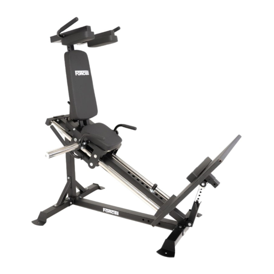
- Page 1 COMPACT STANDING LEG PRESS & HACK SQUAT OWNERS MANUAL | F-CLP-V2...
- Page 2 TABLE OF CONTENTS Parts List Parts Drawing Assembly Step 1 9-11 Assembly Step 2 12-18 Assembly Step 3 19-22 Assembly Step 4 23-26 Assembly Step 5 27-29 Assembly Step 6 30-34...
- Page 3 PARTS LIST KEY NUMBER DESCRIPTION OF PART QUANTITY Back Ground Tube Ground Connection Tube Front Ground Tube Main Stand Tube Main Beam Tube Assembly Flat Washer φ10 Hexagon Bolt M10*90 Lock Nut M10 Hexagon Bolt M10*70 Big Flat Washer φ30*φ10*3 Hexagon Bolt M10*80 Track Inner Pipe Assembly Back Anchor Tube Assembly...
- Page 4 PARTS LIST KEY NUMBER DESCRIPTION OF PART QUANTITY Hexagon Bolt M12*80 T Shape Pin φ12*70 Back Cushion Tube Assembly Back Cushion Adjust Inner Tube Weldment Assembly Double Head Bolt φ12**323-M10 Back Cushion Seat Cushion Calf Tube Assembly Flat Washer φ8 Hexagon Bolt M8*40 Hexagon Bolt M8*70 Handle Right Assembly...
-
Page 5: Table Of Contents
PARTS LIST KEY NUMBER DESCRIPTION OF PART QUANTITY Limit Handle Pipe Weldment Hook Weldment Headless Hexagon Bolt M8*10 Handle Cover φ24.5*280 Tube Plug φ25*50*1.5 Limit Shaft Weldment Sheath φ30*φ25*50 Roller Deep Groove Ball Bearing 6003 Footplate Adjust Outer Casing Weldment Tube Plug φ50*50*2 Footplate Adjust Inner Tube Weldment Tube Plug φ45*45*2... - Page 6 PARTS LIST KEY NUMBER DESCRIPTION OF PART QUANTITY Handle Cover φ24.5*150 Handle Left Weldment Shoulder Cushion Frame Weldment Handle Cover φ24.5*185 Tube Plug φ50*50*2 Hexagon Bolt M10*20 15cm Bolt Length Gauge...
- Page 7 PARTS DRAWING NUMBER PART DESCRIPTION PART PICTURE BK-6023-0100 Back Ground Tube BK-6023-0200 Ground ConnectionTube BK-6023-0300 Front Ground Tube BK-6023-0400 Main Stand Tube Main Beam Tube BK-6023-05 Assembly Track Inner Pipe BK-6023-06 Assembly Back Anchor Tube BK-6023-07 Assembly BK-6023-0503 U Shaped Sheet Track Frame BK-6023-08 Weldment Assembly...
- Page 8 PARTS DRAWING NUMBER PART DESCRIPTION PART PICTURE BK-6023-1400 Inclined Tube Weldment Footplate Adjust Outer BK-6025-16 Casing Weldment Assembly BK-6023-1600 Footplate Weldment Footplate Adjust Inner BK-6025-18 Tube Weldment Assembly Back CushionTube BK-6023-19 Assembly Back Cushion Adjust BK-6023-21 Inner Tube Weldment Assembly BK-6023-2700 Back Cushion BK-6023-2600...
- Page 9 PARTS DRAWING NUMBER PART DESCRIPTION PART PICTURE BK-6023-23 Handle Left Assembly Shoulder Cushion BK-6023-24 Frame Weldment Assembly BK-6023-2500 Shoulder Cushion CX-03011 T Shape Pin HDJ-0100 Spring Collar...
- Page 10 ASSEMBLY STEP 1 KEY NUMBER DESCRIPTION OF PART QUANTITY Back Ground Tube Ground Connection Tube Front Ground Tube Main Stand Tube Main Beam Tube Assembly Flat Washer φ10 Hexagon Bolt M10*90 Lock Nut M10 Hexagon Bolt M10*70 Big Flat Washer φ30*φ10*3 Hexagon Bolt M10*80...
- Page 11 ASSEMBLY DRAWING ASSEMBLY STEP 1 INSTRUCTIONS As shown in the figure, pass M10*70 hexagon bolt-9 and φ10 flat washer-6 through ground connection tube-2, back ground tube-1 and front ground tube-3. 2. Assemble main stand tube-4, main beam tube assembly-5 and back ground tube-1 front ground tube-3 together, and fix them use M10*90 hexagon bolt-7, M10*70 hexagon bolt-9, φ10 flat washer-6 and M10 lock nut-8. 3. Fix main stand tube-4 and main beam tube assembly-5 use M10*80 hexagon bolt-11, φ30* φ10*3 big flat washer-10, φ10 flat washer-6 and M10 lock nut-8.
- Page 12 ASSEMBLY DRAWING MAIN BEAM TUBE KEY NUMBER DESCRIPTION OF PART QUANTITY Main Beam Tube Weldment Tube Plug φ40*80*2...
- Page 13 ASSEMBLY STEP 2 KEY NUMBER DESCRIPTION OF PART QUANTITY Track Inner Pipe Assembly Back Anchor Tube Assembly U Shaped Sheet Track Frame Weldment Assembly Big Flat Washer φ30*φ10*3 Spring Washer φ10 Hexagon Bolt M10*25 Flat Washer φ10 Hexagon Bolt M10*60 Lock Nut M10 Limit Shaft Assembly...
- Page 14 ASSEMBLY DRAWING ASSEMBLY STEP 2 INSTRUCTIONS 1. As shown in the figure, install limit shaft assembly-19 to the main frame. Insert track inner pipe assembly-12 into track frame weldment assembly-15 and assemble them to the main frame. 3. As shown in the figure, assemble back anchor tube assembly-13 and u shaped sheet-14 to the main frame. Fix upper part of track inner pipe assembly-12 use φ30*φ10*3 big flat washer-10, φ10 spring washer-16 and M10*25 hexagon bolt-17.
- Page 15 ASSEMBLY DRAWING BACK ANCHOR TUBE KEY NUMBER DESCRIPTION OF PART QUANTITY Back Anchor Tube Tube Plug φ40*60*2...
- Page 16 ASSEMBLY DRAWING BACK ANCHOR TUBE KEY NUMBER DESCRIPTION OF PART QUANTITY Track Inner Pipe Weldment Stainless Steel Pipe φ49.5*0.6...
-
Page 17: Key Number
ASSEMBLY DRAWING TRACK FRAME WELDMENT KEY NUMBER DESCRIPTION OF PART QUANTITY Track Frame Weldment Roller Assembly Internal Thread Axle φ17*81-M10 Big Flat Washer φ30*φ10*3 Spring Washer φ10 Hexagon Bolt M10*20 Tube Plug 50*70*2 Limit Handle Pipe Weldment Hook Weldment Headless Hexagon Bolt M8*10 Handle Cover φ24.5*280 Tube Plug φ25*50*1.5... -
Page 18: Limit Shaft Weldment
ASSEMBLY DRAWING LIMIT SHAFT KEY NUMBER DESCRIPTION OF PART QUANTITY Limit Shaft Weldment Sheath φ30*φ25*50... -
Page 19: Roller
ASSEMBLY DRAWING ROLLER KEY NUMBER DESCRIPTION OF PART QUANTITY Roller Deep Groove Ball Bearing 6003... - Page 20 ASSEMBLY STEP 3 KEY NUMBER DESCRIPTION OF PART QUANTITY Inclined Tube Weldment Flat Washer φ10 Spring Washer φ10 Hexagon Bolt M10*25 Lock Nut M10 Hexagon Bolt M10*80 Footplate Adjust Outer Casing Weldment Assembly Footplate Weldment Double Head Bolt φ12*270-M10 Footplate Adjust Inner Tube Weldment Assembly Flat Washer φ12 Lock Nut M12 Hexagon Bolt M12*80...
- Page 21 ASSEMBLY DRAWING ASSEMBLY STEP 3 INSTRUCTIONS 1. As shown in the figure, assemble inclined tube weldment-20 to the main frame and fix them use M10*80 hexagon bolt-11, φ10 flat washer-6, M8 lock nut-8 and φ10 spring washer-16. Use φ12*270-M10 double head bolt-23, φ10 flat washer-6 and M8 lock nut-8 to fix footplate weldment-22 on the main frame. Fix footplate adjust inner tube weldment assembly-24 on footplate weldment-22 use M12*80 hexagon bolt-27, φ12 flat washer-25 and M12 lock nut-26. 4. Use M12*80 hexagon bolt-27, φ12 flat washer-25 and M12 lock nut-26 to fix footplate adjust outer casing weldment assembly-21 on the main frame. Insert t shape pin-28 to the main frame.
-
Page 22: Footplate Adjust Outer Casing Weldment
ASSEMBLY DRAWING FOOTPLATE ADJUST OUTER CASING WELDMENT KEY NUMBER DESCRIPTION OF PART QUANTITY Footplate Adjust Outer Casing Weldment Tube Plug φ50*50*2... -
Page 23: Footplate Adjust Inner Tube Weldment
ASSEMBLY DRAWING FOOTPLATE ADJUST INNER TUBE WELDMENT KEY NUMBER DESCRIPTION OF PART QUANTITY Footplate Adjust Inner Tube Weldment Tube Plug φ45*45*2... - Page 24 ASSEMBLY STEP 4 KEY NUMBER DESCRIPTION OF PART QUANTITY Back Cushion Tube Assembly Footplate Adjust Outer Casing Weldment Assembly Back Cushion Adjust Inner Tube Weldment Assembly Double Head Bolt φ12**323-M10 Flat Washer φ10 Lock Nut M10 Flat Washer φ12 Lock Nut M12 Hexagon Bolt M12*80 T Shape Pin φ12*70...
- Page 25 ASSEMBLY DRAWING ASSEMBLY STEP 4 INSTRUCTIONS 1. As shown in the figure, use M12*80 hexagon bolt-27, φ12 flat washer-25 and M12 lock nut- 26 to fix footplate adjust outer casing weldment assembly-21 on the main frame. Use φ12**323-M10 double head bolt-31 and φ10 flat washer-6 and M10 lock nut-8 to fix back cushion tube assembly-29 on the main frame. Assemble back cushion adjust inner tube weldment assembly-30 onto back cushion tube assembly-29, fix them use M12*80 hexagon bolt-27, φ12 flat washer-25 and M12 lock nut-26. Insert t shape pin-28 to the main frame.
-
Page 26: Back Cushion Tube Weldment
ASSEMBLY DRAWING BACK CUSHION TUBE KEY NUMBER DESCRIPTION OF PART QUANTITY Back Cushion Tube Weldment Tube Plug φ40*20*1.5 Pull Pin M18*22*φ10... -
Page 27: Back Cushion Adjust Inner Tube Weldment
ASSEMBLY DRAWING BACK CUSHION ADJUST INNER TUBE WELDMENT KEY NUMBER DESCRIPTION OF PART QUANTITY Back Cushion Adjust Inner Tube Weldment Tube Plug φ45*45*2... - Page 28 ASSEMBLY STEP 5 KEY NUMBER DESCRIPTION OF PART QUANTITY Back Cushion Seat Cushion Calf Tube Assembly Flat Washer φ8 Hexagon Bolt M8*40 Hexagon Bolt M8*70 T Shape Pin φ12*70...
- Page 29 ASSEMBLY DRAWING ASSEMBLY STEP 5 INSTRUCTIONS Assemble calf tube assembly-34 onto the main frame fix them use t shape pin-28. Use M8*40 hexagon bolt-36 and φ8 flat washer-35 fix back cushion-32 on the main frame. Use M8*70 hexagon bolt-37 and φ8 flat washer-35 fix seat cushion-33 on the main frame.
- Page 30 ASSEMBLY DRAWING CALF TUBE KEY NUMBER DESCRIPTION OF PART QUANTITY Calf Tube Weldment Calf Non Slip Pad Tube Plug 50*70*2 Flat Round Head Blind Rivet 4*10...
- Page 31 ASSEMBLY STEP 6 KEY NUMBER DESCRIPTION OF PART QUANTITY Handle Right Assembly Handle Left Assembly Flat Washer φ10 Hexagon Bolt M10*25 Lock Nut M10 Shoulder Cushion Frame Weldment Assembly Shoulder Cushion Flat Washer φ8 Hexagon Bolt M8*70 Spring Collar φ50...
- Page 32 ASSEMBLY DRAWING ASSEMBLY STEP 6 INSTRUCTIONS Use M8*70 hexagon bolt-37 and φ8 flat washer-35 fix shoulder cushion-41 on shoulder cushion frame weldment assembly-40. 2. Use M10*25 hexagon bolt-17, φ10 flat washer-6 and M10 lock nut-8 fix handle right assembly-38 and handle left assembly-39 on the main frame. Assemble spring collar-20 on the main machine.
- Page 33 ASSEMBLY DRAWING RIGHT HANDLE KEY NUMBER DESCRIPTION OF PART QUANTITY Handle Right Weldment Stainless Steel Outer Pipe φ49.5*0.6 Barbell Rod Inner Pipe φ48*1.5 Outer Support Sleeve φ50*φ44.8*φ25.5 Barbell Hanging Rod Inner Support Sleeve φ70*φ44.8*φ25.5*30 Hexagon Socket Button Head Screws M8*25 Handle Cover φ24.5*150...
- Page 34 ASSEMBLY DRAWING LEFT HANDLE KEY NUMBER DESCRIPTION OF PART QUANTITY Handle Left Weldment Stainless Steel Outer Pipe φ49.5*0.6 Barbell Rod Inner Pipe φ48*1.5 Outer Support Sleeve φ50*φ44.8*φ25.5 Barbell Hanging Rod Inner Support Sleeve φ70*φ44.8*φ25.5*30 Hexagon Socket Button Head Screws M8*25 Handle Cover φ24.5*150...
- Page 35 ASSEMBLY DRAWING SHOULDER CUSHION FRAME WELDMENT KEY NUMBER DESCRIPTION OF PART QUANTITY Shoulder Cushion Frame Weldment Handle Cover φ24.5*185 Tube Plug φ50*50*2...
Need help?
Do you have a question about the COMPACT STANDING LEG PRESS & HACK SQUAT and is the answer not in the manual?
Questions and answers