
Related Manuals for ASROCK Rack Paul


Summary of Contents for ASROCK Rack Paul
- Page 1 PAUL User Manual Version 1.0 Published May 2022 Copyright©2022 ASRock Rack INC. All rights reserved.
- Page 2 In no event shall ASRock Rack, its directors, officers, employees, or agents be liable for any indirect, special, incidental, or consequential damages (including damages for loss of profits, loss of business, loss of data, interruption of business and the like), even if ASRock Rack has been advised of the possibility of such damages arising from any defect or error in the documentation or product.
- Page 3 Contact Information If you need to contact ASRock Rack or want to know more about ASRock Rack, you’re welcome to visit ASRock Rack’s website at www.ASRockRack.com; or you may contact your dealer for further information. ASRock Rack Incorporation 6F., No.37, Sec. 2, Jhongyang S. Rd., Beitou District,...
-
Page 4: Table Of Contents
Contents Chapter 1 Introduction Features System Requirements Package Contents Specifications Motherboard Layout Onboard LED Indicators I/O Panel Chapter 2 Installation Installing the IPMI Card Jumper Setup Onboard Headers and Connectors Chapter 3 Connection Connections to MB for Power On/Off & Reboot Features Chapter 4 Management Interface Web-based User Interface 4.1.1... - Page 5 4.6.1 Date & Time 4.6.2 KVM Mouse Setting 4.6.3 Services Remote Control 4.7.1 Remote KVM Interface Power Control...
-
Page 7: Chapter 1 Introduction
• ADC Device Support (Customizable) • GPIO Device Support (Customizable) 1.2 System Requirements Before you install the PAUL Card, please check if the client device meets the following requirements. • Motherboard that supports PAUL Card • LAN(RJ-45) port for server management • Firefox (Windows and Linux), Chrome (Windows and Linux), Edge-Chromium... -
Page 8: Specifications
1.4 Specifications PAUL Type Low-Profile PCIe IPMI Card Chipset ASPEED VIDEO PROCESSOR AST2500A2-GP Onboard RAM System: 384MB Video 1 (64MB) Onboard ROM 64MB Interface PCIe 3.0 x1 interface 1 x D-sub support max. resolution 1920 x 1200 @ 60Hz External... -
Page 9: Motherboard Layout
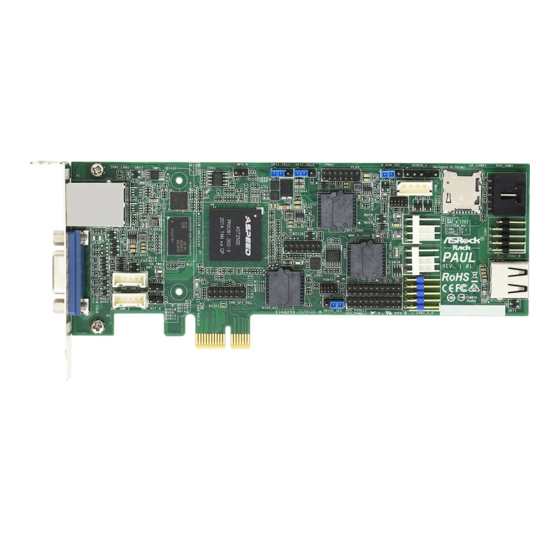
PAUL 1.5 Motherboard Layout 16.85cm (6.7in) SPI1_SEL1 SPI1_SEL2 D_ROM_SEL TPMS1 SD_CARD1 IPMB_1 IPMI_LAN1 PSU_SMB1 (PAUL only) FAN1 COM1 TPMS2 FAN2 BMC_SMB_1 USB2_B AUX_PENEL2 NMI_BTN1 BMC_SMB_2 VBIOS_SEL1 USB2_3_4 AUX_PENEL1 PCIE1 Description SPI Selection Jumper (SPI_SEL1) SPI Selection Jumper (SPI_SEL2) TPM Header (TPMS1) -
Page 10: Onboard Led Indicators
1.6 Onboard LED Indicators Status Description BMC_B_LED1 Yellow Using BMC ROM2 LAN1_LED FAN1 failed FAN2_LED FAN2 failed BMC_A_LED1 Yellow Using BMC ROM1 BMC_LED1 Green BMC heartbeat LED SYSTEM_ERR_LED STB PWR ready SB_PWR1 Green SYSTEM error... -
Page 11: I/O Panel
PAUL 1.7 I/O Panel Right Side Left Side Description Connect a LAN cable to this IPMI_LAN1 LAN RJ-45 Port (IPMI_LAN1) port for remote management feature. Connect one end of the VGA cable to this VGA Port (VGA1) VGA port and the other end to the monitor. -
Page 12: Chapter 2 Installation
Chapter 2 Installation This is a Proprietary form factor (6.7-in x 2.2-in, 16.85 cm x 5.62 cm) IPMI Card. Before you install the IPMI Card, study the configuration of your chassis to ensure that the card is compatible with your system. Make sure to unplug the power cord before installing or removing the IPMI card. -
Page 13: Jumper Setup
PAUL 2.2 Jumper Setup The illustration shows how jumpers are setup. When the jumper cap is placed on the pins, the jumper is “Short”. If no jumper cap is placed on the pins, the jumper is “Open”. The illustration shows a 3-pin jumper whose pin1 and pin2 are “Short”... -
Page 14: Onboard Headers And Connectors
SMB, internet status indicator. Connect Pin 3 (GPIOD1) & Pin 7 (GPIOD3) to MB Power On/Off & Reset button. Connects BMC_GPIO from PAUL Card to the (19-pin AUX_PANEL2) Motherboard. (see p.3, No. 14) TPM Headers This connector supports... - Page 15 PAUL Intelligent Platform This 4-pin connector is used IPMB_SDA Management Bus Header to provide a cabled base-board IPMB_SCL (4-pin IPMB_1) or front panel connection for (see p.3, No. 5) value added features and 3rd- party add-in cards, such as No Connect...
- Page 16 System Fan Connectors Please connect fan cables to the FAN_SPEED_CONTROL (4-pin FAN1) fan connector and match the FAN_SPEED (see p.3, No. 10) FAN_VOLTAGE black wire to the ground pin. (4-pin FAN2) All fans support Fan Control. (see p.3, No. 11) Non Maskable Interrupt Please connect a NMI device Button Header...
-
Page 17: Chapter 3 Connection
Chapter 3 Connection 3.1 Connections to MB for Power On/Off & Reboot Features 1. Please first make sure "IPMI_LAN1" on the Paul card is connected to an active network. 2. Connect "USB_PWR" pin to "5VSB" pin of the Aux/System Panel header on your motherboard. - Page 18 3. Connecot "BMC_GPIOD1" pin to "PWRBTN#" pin of the System Panel on your motherboard. Paul IPMI Card Motherboard AUX_PANEL1 System Panel Header Header BMC_GPIOD1 PWRBTN# 4. Connecot "BMC_GPIOD3" pin to "RESETCON#" pin of the System Panel on your motherboard. Paul IPMI Card...
-
Page 19: Chapter 4 Management Interface
PAUL Chapter 4 Management Interface 4.1 Web-based User Interface The web-based user interface allows you to easily monitor the client device’s hardware information including temperatures, fan rotations, voltages, and power. By opening the GUI in a browser you can manage the client device remotely, even when there is no OS installed on the client device. -
Page 20: Using The Utility
4.1.2 Using the Utility The web-based graphics user interface displays when you login in the utility successfully. Click on a function from the list on the left hand side to start using its specific functions. -
Page 21: Dashboard
PAUL 4.2 Dashboard The dashboard gives you a quick overview of the system status, quick control options, poweron hours, power redundancy, sensors, messages, and logs. Click or hover your mouse over an item to see more details. Scroll down to view more items. -
Page 22: Sensor
4.3 Sensor The Sensor Readings page displays live readings for all the available sensors with details like Sensor Name, Status, Current Reading and Behavior. This page will automatically refresh itself with data from the database. Please note that there may be some delay when retrieving live data. -
Page 23: Fru Information
PAUL 4.4 FRU Information This Page displays the BMC’s FRU (Field Replaceable Units) device information. The FRU page shows Basic Information, Chassis Information, Board Information and Product Information of the FRU device. Scroll down to view more items. -
Page 24: Ipmi Event Log
4.5 IPMI Event Log This page displays the list of events incurred by different sensors on this device. Click on a record to see the details of that entry. Hovering over the graph will allow you to view the number of events by date. -
Page 25: Setting
PAUL 4.6 Setting This page allows you to configure the BMC settings. Click on an item for more options. 4.6.1 Date & Time This page allows you to set the date and time on the BMC. You can either select a time zone... - Page 26 4.6.2 KVM Mouse Setting This page allows you to set the mouse mode. The Redirection Console handles mouse emulation from local window to remote screen using either of the three methods. Only the Administrator has the permissions to configure this option. 4.6.3 Services This page lists services running on the BMC.
- Page 27 PAUL 4.7 Remote Control This menu allows you to perform remote operations on the server. Click Launch H5Viewer to start the remote KVM. 4.7.1 Remote KVM Interface This page lists services running on the BMC. It shows current status and other basic...
- Page 28 4.8 Power Control The Power Control displays the current server power status and allows you to change the current settings. Select the desired option, and then click Perform Action to execute the selected action.
Need help?
Do you have a question about the Paul and is the answer not in the manual?
Questions and answers