Table of Contents
Advertisement
Quick Links
NTSC/PAL
SAFETY PRECAUTION FOR SERVICE MANUAL ............................................................................................................. 2
VOLTAGE SELECTION ....................................................................................................................................................... 2
AC POWER SUPPLY CORD AND AC PLUG ADAPTOR ................................................................................................... 2
SPECIFICATIONS ............................................................................................................................................................... 3
NAMES OF PARTS ............................................................................................................................................................. 4
OPERATION MANUAL ........................................................................................................................................................ 6
DISASSEMBLY ................................................................................................................................................................... 8
REMOVING AND REINSTALLING THE MAIN PARTS .................................................................................................... 10
ADJUSTMENT .................................................................................................................................................................. 12
TEST MODE ..................................................................................................................................................................... 15
ERROR LIST..................................................................................................................................................................... 17
NOTES ON SCHEMATIC DIAGRAM ............................................................................................................................... 19
TYPES OF TRANSISTOR AND LED ................................................................................................................................ 19
BLOCK DIAGRAM ............................................................................................................................................................ 20
SCHEMATIC DIAGRAM / WIRING SIDE OF P.W.BOARD .............................................................................................. 26
VOLTAGE ......................................................................................................................................................................... 40
WAVEFORMS OF CD CIRCUIT ....................................................................................................................................... 41
TROUBLESHOOTING ...................................................................................................................................................... 42
FUNCTION TABLE OF IC ................................................................................................................................................. 49
LCD SEGMENT ................................................................................................................................................................ 62
PARTS GUIDE/EXPLODED VIEW
SERVICE MANUAL
CONTENTS
SHARP CORPORATION
- 1 -
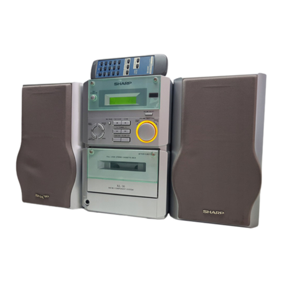
VIDEO CD MICRO SYSTEM
MODEL
XL-30V Video CD Micro System consisting of XL-30V (main unit)
and CP-XL30V (speaker system).
• In the interests of user-safety the set should be restored to its original
condition and only parts identical to those specified should be used.
This document has been published to be used
for after sales service only.
The contents are subject to change without notice.
XL-30V
No. S0081XL30V///
XL-30V
Page
Advertisement
Table of Contents

Related Manuals for Sharp XL-30V


Summary of Contents for Sharp XL-30V
-
Page 1: Table Of Contents
VIDEO CD MICRO SYSTEM XL-30V MODEL XL-30V Video CD Micro System consisting of XL-30V (main unit) and CP-XL30V (speaker system). • In the interests of user-safety the set should be restored to its original condition and only parts identical to those specified should be used. -
Page 2: Safety Precaution For Service Manual
XL-30V SAFETY PRECAUTION FOR SERVICE MANUAL Precaution to be taken when replacing and servicing the Laser Pickup. The AEL (Accessible Emission Level) of Laser Power Output for this model is specified to be lower than Class 1 Requirements. However, the following precautions must be observed during servicing to protect your eyes against exposure to the Laser beam (1) When the cabinet has been removed, the power is turned on without a compact disc, and the Pickup is on a position outer than the lead-in position, the Laser will light for several seconds to detect a disc. -
Page 3: Specifications
XL-30V FOR A COMPLETE DESCRIPTION OF THE OPERATION OF THIS UNIT, PLEASE REFER TO THE OPERATION MANUAL. SPECIFICATIONS XL-30V General Tuner section Power source: Frequency range: AC 110 - 127/220 - 240 V, FM; 88-108 MHz 50/60 Hz AM; 531-1,602 kHz... -
Page 4: Names Of Parts
XL-30V NAMES OF PARTS XL-30V Front panel 1. Timer Indicator 2. Record Indicator 3. Sleep Indicator 4. (VCD/CD) Repeat Indicator 5. (VCD/CD) Play Indicator 6. (VCD/CD) Random Indicator 7. (VCD/CD/TUNER) Memory Indicator 8. FM Stereo Mode Indicator 9. FM Stereo Indicator 10. - Page 5 XL-30V XL-30V Remote control 1. Remote Control Transmitter LED 2. Timer Button 3. (VCD/CD) Audio Mode Button 4. (VCD/CD) Direct Search Buttons 5. (VCD/CD) Display Button 6. (VCD) Video Intro Button 7. Sleep Button 8. On/Stand-by Button 9. (VCD) TV Type Button 10.
-
Page 6: Operation Manual
XL-30V OPERATION MANUAL – 6 –... - Page 7 XL-30V – 7 –...
-
Page 8: Disassembly
XL-30V DISASSEMBLY Caution on Disassembly XL-30V Follow the below-mentioned notes when disassembling (A1)x1 Top Cabinet ø3x10mm the unit and reassembling it, to keep it safe and ensure CD PWB excellent performance: (B2)x1 Display 1. Take cassette tape and compact disc out of the unit. - Page 9 XL-30V (K2)x1 (K2)x2 (K1)x4 ø2x10mm Video PWB (L1)x4 ø2.5x14mm (L2)x1 (M1)x3 ø2.5x10mm (L2)x1 (L2)x1 PWB Washer x3 CD PWB CD Mechanism Top Cabinet (L4)x1 (L4)x2 (L3)x2 Top Cabinet Open/Close Switch PWB CD Mechanism CD Motor PWB Figure 9-1 Figure 9-2...
-
Page 10: Removing And Reinstalling The Main Parts
XL-30V REMOVING AND REINSTALLING THE MAIN PARTS TAPE MECHANISM SECTION (A2)x1 (A2)x1 Perform steps 1 to 7 and 9 of the disassembly method to ø2x7mm ø2x3mm remove the tape mechanism. (See page 8.) (A1)x2 How to remove the record / playback and erase ø2x8mm... - Page 11 XL-30V How to remove the flywheel (See Fig. 11-1.) (E1)x1 Stop Washer 1. Remove the belt. Mechanism Chassis 2. Remove the stop washer (E1) x 1 pc., with a small precision Driver Stop screwdriver to extract the flywheel from the capstan metal.
-
Page 12: Adjustment
XL-30V ADJUSTMENT CD SECTION Since this CD system incorporates the following automatic adjustment function, when the pickup is replaced, it is not necessary to readjust it. VIDEO CD SECTION A-BEX Model No. TVD-581 TEST VIDEO CD TVD-581A • Measurement of oscillation frequency... - Page 13 XL-30V Checking of vector scope waveform Disc Checking Setting Checking Item Track 2 VIDEO OUT Set the phase of Phase check ± 10° color burst signal (B) to 180°-360° line. Check that the setting is within the illustrated range.) [NTSC]...
- Page 14 XL-30V • FM Detection MECHANISM SECTION Signal generator: 10.7 MHz, FM sweep generator • Driving Force Check Test Frequency Frequency Setting/ Instrument Torque Meter Specified Value Stage Display Adjusting Connection Play: TW-2412 Over 80 g Parts • Torque Check FM IF 10.7 MHz...
-
Page 15: Test Mode
XL-30V TEST MODE The test mode applied to this microcomputer has three modes, namely ordinary test mode to be used for adjustment or measurement, aging test mode to be used for aging test, and self-diagnosis test mode for self-inspection in case of final product inspection. - Page 16 XL-30V 3. Preset frequencies for various destinations (random preset memory) BAND Ordinary 1,China BAND Ordinary 1,China FM 87.50 MHz 16-20 FM108.00 MHz 21-25 FM STEREO FM 98.00 MHz FM106.00 MHz FM 90.00 MHz FM 90.00 MHz FM106.00 MHz FM MONO FM 98.00 MHz...
-
Page 17: Error List
XL-30V 6. Key input diagnosis Test Mode (TEST 6) When the test mode is set, the following indication appears. This test mode is intended to check whether all the main unit buttons can be detected. Accordingly, in this test mode checking as to whether the "POWER"... - Page 18 XL-30V TAPE mechanism error display (1) Error contents ......Displayed when not becomes "ON" while the mechanism operating detection SW "CAM-SW" is being operated even though the motor or solenoid are controlled to operate the tape for playback/ FF/REW/Recording. Major cause ....... When displayed even though the mechanism is working, failure of CAM-SW and connection failure.
-
Page 19: Notes On Schematic Diagram
XL-30V NOTES ON SCHEMATIC DIAGRAM • Resistor: • The indicated voltage in each section is the one measured To differentiate the units of resistors, such symbol as K and by Digital Multimeter between such a section and the chas- M are used: the symbol K means 1000 ohm and the symbol sis with no signal given. -
Page 20: Block Diagram
XL-30V V_GND V_5V REGULATOR Q11V 3.3V IC10V IX0035SJ ROM 256K x 16 VSSK AUX4 LA12 /BUSY LA13 AUX3/DSASTB LA14 AUX2/DATA LA15 AUX1/DSADATA LA16 AUX0/DSAACK LA17 PCLKQSCN AUDIO_CLK PCLK2XSCN AUDIO_DATA DCLK IC15V BCLK HSYNC ES3880F VSYNC VIDEO CD DECODER DRAS1/DOE YUV7... - Page 21 XL-30V IC11V NJM4555M BUFFER AMP. R_CH A_GND L_CH A_12V VDAC V_GND V_AMP Q12V VD_DO VD_DI BUSY VD_STB CNP809 XL100V 27MHz 27MHz 80 79 78 77 76 75 74 73 72 71 70 69 68 67 66 65 64 63 62 61 60 59 58 57 56 55 54 53 52 51...
- Page 22 XL-30V LCD701 D704-709 COM1 COM3 COM0 CFW701 VLC3 COM2 VLC2 VLC1 SWITCHING OSC2 IC701 OSC1 X701 A_12V Q707 IX0030S LED+B 8MHz SYSTEM CON MICROCOMP X702 MMOD 32.768kHz VREF CLID_SW SW709-SW710 Q706 KEY1 SWITCHING SW711-SW713 KEY2 MODEL SW721-SW728 CLID_PRO TAPE_SW SW700...
- Page 23 XL-30V D701 CL ID_SW SEG27 CLID_OUT SEG25 COM3 SEG28 VD_DO COM2 SEG26 SEG29 VD_DI SEG30 BUSY SEG31 SEG32 VD_STB SEG33 CD_STB IC701 IX0030SJ CLID_DW CNS702 SYSTEM CONTROL CLID_UP CLID_OUT MICROCOMPUTER MVOL_DW MVOL_UP TAPE_SW MVOL_UP A_12V MVOL_IND M_12V SURR IC702 D_GND...
- Page 24 XL-30V CNP301 FM MUTE LEVEL SWITCHING T302 VR351 ANTENNA VD301-1 10K(B) TERMINALS AM ANT. R_MUTE SVC348S Q351 AM OSC OUT X351 SO301 456kHz FM ANTENNA TERMINALS 14 13 IC303 LA1832 T306 FM IF DET./FM MPX./AM IF AM OSC. VD301-2 SVC348S...
- Page 25 XL-30V CNS704 REC R-CH FM ST R-CH OUT TAPE R TUN R R_MUTE CD R TO DISPLAY CD+B P MUTE P-STB IC401 LOGIC LC75342M FUNCTION/VOLUME EQUALIZER CD L TUN L TAPE L A_12V REC L-CH L-CH OUT L-IN L-CH L-CH...
-
Page 26: Schematic Diagram / Wiring Side Of P.w.board
XL-30V VD_DO VD_DI R837 BUSY VD_STB C844 CD_STB VD_STB P33 12 - C BUSY CNS702 VD_DI FROM VD_DO DISPLAY PWB CLID_OUT CLID_SW X802 8MHz OPEN/CLOSE SWITCH PWB-A6 SW801 OPEN/CLOSE R839 2.2K R815 L803 C823 C822 10µH L801 0.01 220/10 R813 10µH... - Page 27 XL-30V R837 R848 R832 R836 2.2K 11 10 C844 R842 R893 MPACK MECHA R841 R894 TEST MPDATA DATA /RESET R840 R895 MPSTB R896 MPRST IC806 MPRST XOUT IX0031SJ X802 8MHz CD SERVO AVSS MICROCOMPUTER M_GND P31 8 - H C854...
- Page 28 XL-30V Q11V 2SD1858R2 3.6V C105V C125V R143V 100/10 4.3V P27 12 - C V_GND CNS810 V_8V FROM CD PWB IC10V C126V IX0035SJ C112V ROM 256Kx16 C115V 100/10 PGM/A18 R98V R97V R96V 4.7K 4.7K 4.7K R90V 14 13 12 11 10 9 8 R91V 4.7K...
- Page 29 XL-30V IC11V R115V C171V 10/25 NJM4565M C144V BUFFER AMP. 33P(CH) C143V R108V R107V R116V C172V 33P(CH) 10/25 A_12V C167V R101V R186V 22P(CH) 100K GND_A R102V 100K R187V R189V R190V R183V 100K R111V VDAC R184V 100K GND_V R113V C101V R195V C137V C139V 1000/6.3...
- Page 30 XL-30V IC303 FM IF DET./FM MPX./AM IF AM ANT. AM TRACKING FM MUTE LA1832S LEVEL T302 C301 C331 SWITCHING 0.001 0.047 Q351 4.7V KRC104 M C371 R361 (0V) L353 1/50 C329 D301 0.022 1N4148 R362 C372 1/50 R336 R366 R323...
- Page 31 XL-30V P33 12 - F FROM DISPLAY PWB C406 CFW704 10/16 STEREO R440 FM ST 3.9K SWITCHING R436 Q351 C404 KRC104 M 10/16 R416 C402 CD+B 10/16 P MUTE 15 14 13 12 11 10 IC401 P-STB R366 FUNCTION/VOLUME 2.2K...
- Page 32 XL-30V SW728 VOLUME/JOG D709 D707 D708 SW727 MPG3372X MPG3372X MPG3372X R705 FUNCTION 5.6K R7D3 R7D5 R7D8 SW726 R706 TUNING DOWN D706 D704 D705 3.9K MPG3372X MPG3372X MPG3372X SW725 R707 R7D9 R7D6 R7D1 STOP/ CLEAR 2.7K LED PWB-A4 SW724 R708 SW713 REC.
- Page 33 XL-30V DISPLAY PWB-A2 LCD701 LCD DISPLAY 98 97 96 95 94 93 92 91 90 89 88 87 86 85 84 83 82 81 80 79 78 77 76 SEG24 COM3 SEG25 COM2 SEG26 COM1 SEG27 COM0 SEG28 SEG29 VLC3...
- Page 34 XL-30V POWER PWB-B F651 D652 D651 T2.5A L 250V 1N4004 1N4004 C652 C651 C653 C654 220-240V D653 D654 1N4004 1N4004 110-127V B1GND CD+B C695 T651 0.001 MAIN POWER TRANSFORMER IC682 KIA7805AP VOLTAGE REGULATOR D663 1N4004 13.0V C663 Q673 C676 2SD2012 Y D664 8.6V...
- Page 35 XL-30V TO TAPE MECHANISM GND (226) TO MAIN CHASSIS GND CNS653 (288) FROM C660 C696 DISPLAY PWB CNP653 CNS707 P37 12 - F D684 D686 D683 C695 CNS652 D682 Q683 P36 1 - A D681 E C B CNP652 TO MAIN PWB...
- Page 36 XL-30V ANTENNA SO401 TERMINALS SO601 VIDEO OUT SPEAKER AM LOOP SO301 TERMINALS ANTENNA FM 75 OHMS P35 5 - B L-CH R-CH FROM POWER PWB CNS652 C376 CNP301 C301 Q305 C397 E C B C316 C614 R304 R381 C319 C613...
- Page 37 XL-30V R743 R775 R741 1 2 3 4 5 6 7 8 9 10 11 R779 R701 R740 CNS703 SW710 R702 R756 SW722 CLOCK/ R739 R750 SW709 BASS/ TIMER/ ON/STAND-BY TREBLE SLEEP R751 R749 X702 R752 CNS702 SW721 R733 C701...
- Page 38 XL-30V NM801 SLED MOTOR CD MOTOR PWB-C NM802 F3895AF SPINDLE MOTOR NSW801 OPEN/CLOSE PICKUP IN SWITCH PWB-A6 P36 6 - F TO MAIN PWB CFW807 CNP605 SW801 OPEN/ CLOSE PICKUP UNIT (306) CNS605A 1 2 3 4 5 6 P35 6 - C...
- Page 39 XL-30V C169V R90V R171V IC17V R97V R98V C136V R143V R194V R91V C150V R96V R137V R111V R112V R178V R138V C105V R93V R139V R141V C131V R140V R153V R155V IC14V 10 15 20 25 R161V IC15V R164V R160V C106V C135V 5 10 C130V...
-
Page 40: Voltage
XL-30V VOLTAGE IC101 IC401 IC802 IC806 IC701 IC14V NO. VOLTAGE NO. VOLTAGE NO. VOLTAGE NO. VOLTAGE NO. VOLTAGE NO. VOLTAGE NO. VOLTAGE NO. VOLTAGE — 2.5V 2.6V 2.5V 2.5V 4.6V 2.5V 2.5V — 1.3V 2.5V 2.7V — 0.3V(8.3V) 2.5V 2.6V 3.1V... -
Page 41: Waveforms Of Cd Circuit
XL-30V WAVEFORMS OF CD CIRCUIT NO DISC FOCUS SEARCH STOP PLAY TMAX IC802 17pin IC802 33pin SBOK IC804 26pin IC802 8pin IC804 25pin IC802 41pin FOCUS SEARCH TOC IL STOP PLAY IC802 38pin IC802 31pin IC802 29pin IC802 34pin IC802 31pin... -
Page 42: Troubleshooting
XL-30V TROUBLESHOOTING When the CD does not function When the CD section does not operate when the objective lens of the optical pickup is dirty, this section may not operate. Clean the objective lens, and check the playback operation. When this section does not operate even after the above step is taken, check the following items. - Page 43 Is the sending waveform (8MHz) also on the 16 pin? If OK, IC807 or IC806 are defective. Is the SHARP logo displayed on the TV screen? Check the items of "SHARP logo is not displayed". Is "Er-CD30" displayed on the LCD? Check the items of "Communication error".
- Page 44 XL-30V • The SHARP logo is not displayed. Is the voltage on pin 52 (VREF) on IC14V (ES2883F) about 1.3V? Check C150V. Is a 13.5MHz clock signal available at pin 79 (PCLK) on IC14V? Check the soldering on IC14V and the voltage at each pin.
- Page 45 XL-30V • Laser abnormal Is +6.2V on the emitter of Q861? Check the PWB pattern between the 2 pin of BI605B/ CNS605B and the emitter of Q861. Is +5V on the collector of Q861? Check around IC804 and Q861. Is +5V on the 64 pin (VDD) of IC802? Check the PWB pattern between IC807 and the 64 pin of IC802.
- Page 46 XL-30V • HF abnormal Is signal (tracking error signal) outputted to 31 (TEI) and 32 (TEZI) Signal on the 2 and 5 pins The pickup is defective. pins of IC802 when starting CD disc rotation and during CD of BI802/CNS802.
- Page 47 XL-30V • Abnormal of track search Does the feed motor for the pickup run when pressing FF/REW key Check as specified in "Feed motor abnormal." during CD playing and moving track No. of LCD UP/DOWN? Is the following waveform outputted to the 34 pin (TRO) of IC802 IC802 is defective.
- Page 48 XL-30V • No sound is heard. Whilst the disc is playing, is a signal present at pins 89, 90, 91 on IC15 is defective. IC15V? (Refer to the waveform shown in Figure 48.) IC14 is defective. Is an audio signal present at pins 45 ~ 48 on IC14V? Check IC11V and the peripheral parts.
-
Page 49: Function Table Of Ic
XL-30V FUNCTION TABLE OF IC IC401 VHiLC75342M-1: Function/Volume Equalizer (LC75342M) Pin No. Port Name Function Serial data and clock input pin for control. Chip enable pin. Data written into an internal latch in a timing of [H] -> [L]. Each analog switch is activated. - Page 50 XL-30V IC701 RH-iX0030SJZZ: System Control Microcomputer (IX0030SJ) (1/2) Pin No. Terminal Name Port name Input/Output Function COM3-COM0 COM3-COM0 Output LCD common output terminal. VLC3-VLC1 VLC3-VLC1 — LCD power terminal. — Microcomputer power +5V. OSC2 OSC2 Output Oscillator connecting terminal for main clock. f=8MHz...
- Page 51 XL-30V IC701 RH-iX0030SJZZ: System Control Microcomputer (IX0030SJ) (2/2) Pin No. Terminal Name Port name Input/Output Function LED4/S50 A17/P54 JOG_DOWN Input Jog dial DOWN pulse input. SEG49 P60/A0 Output Not used. SEG48 P61/A1 P-STB Output POWER IC STND-BY terminal CONTROL "L" = POWER STAND-BY "H" = POWER IC ON...
- Page 52 XL-30V IC801 VHiTA2147F/-1: Servo Pre Amp. (TA2147F) Pin No. Terminal Name Input/Output Function — 3.3V power terminal. Input Main beam amplifier input terminal. Input Main beam amplifier input terminal. Input Sub-beam amplifier input terminal. Input Sub-beam amplifier input terminal. Input Monitor photo diode amplifier input terminal.
- Page 53 XL-30V IC802 VHiTC9490F/-1: Servo/Signal Control (TC9490F) (1/2) Pin No. Port Name Input/Output Function Output Bit clock output terminal. 32fs, 48fs, 84fs can be selected by command. LRCK Output LR channel clock output terminal. When L channel "L", when R channel "H". The output polarity can be reversed by command.
- Page 54 XL-30V IC802 VHiTC9490F/-1: Servo/Signal Control (TC9490F) (2/2) Pin No. Port Name Input/Output Function AVDD3 — Analog 3.3 V power terminal. Output Feed equalizer output terminal. Output Disc equalizer output terminal. VSS3 — Digital GND terminal. VDD3 — Digital 3.3 V power terminal.
- Page 55 XL-30V IC804 VHiLA6548D/-1: Focus/Tracking/Spin/Sled Driver (LA6548D) Pin No. Port Name Function Power (short-circuit with pin 30) MUTE All channels output ON/OFF VIN1 CH1 input terminal CH1 input terminal (for gain control) VO1+ CH1 output terminal (counter-inversion) VO1- CH1 output terminal (inversion) GND terminal.
- Page 56 XL-30V IC806 RH-iX0031SJZZ: CD Servo Microcomputer (IX0031SJ) Pin No. Port Name Terminal Name Input/Output Function P73-P70 BUS3-BUS0 Input/Output Output Commands to TC9490F and data I/O BUCK Output Clock Signal to TC9490F Output TC9490F Chip Enable 7*,8* P05, P04 Output Not used...
- Page 57 XL-30V IC14V VHiES3883F/-1: Video CD Encoder (ES3883F) (1/2) Pin No. Terminal Name Input/Output Function Input Ground. 2*-4* — No connect. Do not connect to these pins. Input Voltage supply, 5V. DSC_C Input Clock for programming to access internal registers. AUX0 Input/Output Servo Forward Control pin.
- Page 58 XL-30V IC14V VHiES3883F/-1: Video CD Encoder (ES3883F) (2/2) Pin No. Terminal Name Input/Output Function AOR + Output Right channel output. AOR - Output Right channel output. AOL - Output Left channel output. AOL + Output Left channel output. MIC1 Input Microphone input 1.
- Page 59 XL-30V IC14V VHiES3883F/-1 :Video CD Encoder (ES3883F) MIC2 DSC_D7 MIC1 HSYN_B AOL + DSC_D6 AOL - VSYN_B AOR - DSC_D5 AOR + YUV7 VCCAA YUV6 VREFP YUV5 IC14V YUV4 VSSAA AUX15/IR ES3883F AUX14/SOS1 YUV3 AUX13/SP DSC_D4 RBCK/SER_IN YUV2 AUX12/C2PO DSC_D3...
- Page 60 XL-30V IC15V VHiES3880F/-1: Video CD Decoder (ES3880F) Pin No. Terminal Name Input/Output Function Input Voltage supply for 3.3V. RAS# Output DRAM row address strobe (active low). DWE# Output DRAM write enable (active low). 4-12 DA0-DA8 Output DRAM multiplaxed row and column address bus.
- Page 61 XL-30V IC15V VHiES3880F/-1: Video CD Decoder (ES3880F) 80 79 78 77 76 75 74 73 72 71 70 69 68 67 6665 64 63 62 61 60 59 58 57 56 55 54 53 52 51 LA12 AUX4 LA13 AUX3...
-
Page 62: Lcd Segment
XL-30V LCD SEGMENT LCD701: RV-LX0008SJZZ 1 2 3 4 5 6 7 8 9 10 11 12 13 14 15 16 17 18 19 20 21 22 23 24 PinNo com1 com2 com3 com4 PinNo com1 com2 com3 com4 com1... - Page 63 PARTS GUIDE VIDEO CD MICRO SYSTEM XL-30V MODEL XL-30V Video CD Micro System consisting of XL-30V (main unit) and CP-XL30V (speaker system). “HOW TO ORDER REPLACEMENT PARTS” To have your order filled promptly and correctly, please furnish the For U.S.A. only following information.
- Page 64 XL-30V PRICE PRICE DESCRIPTION PARTS CODE PARTS CODE DESCRIPTION RANK RANK D685 VHD1N4004//-1 AB Silicon,1N4004 XL-30V D686 VHD1N4004//-1 AB Silicon,1N4004 D688,689 VHD1N4004//-1 AB Silicon,1N4004 INTEGRATED CIRCUITS D704~709 VHPMPG3372X-V AD LED,Green,MPG3372X D720~723 VHD1N4148//-1 AA Silicon,1N4148 D730 VHPHY2043//-1 AD LED,Orange,HY2043 IC10V RH-IX0035SJZZ ROM 256K×16,IX0035SJ...
- Page 65 XL-30V PRICE PRICE PARTS CODE DESCRIPTION PARTS CODE DESCRIPTION RANK RANK AA 0.1 µF,25V AB 10 µF,16V,Electrolytic C108V VCKYTV1EB104K C364 RC-GZA106AF1C AB 0.015 µF,50V,Mylar AA 0.022 µF,25V C109,110 VCQYKA1HM153J J C365 VCKYTV1EF223Z AB 100 µF,10V,Electrolytic AA 0.001 µF,50V C109V RC-GZA107AF1A...
- Page 66 XL-30V PRICE PRICE PARTS CODE DESCRIPTION PARTS CODE DESCRIPTION RANK RANK AB 0.015 µF,25V C802 VCKYTV1EB153K R95V VRS-TV2AB682J AA 6.8 kohms,1/10W AB 47 µF,10V,Electrolytic C803 RC-GZA476AF1A R96V~98V VRS-TV2AB472J AA 4.7 kohms,1/10W AA 0.01 µF,25V C804 VCKYTV1EB103K R100V VRS-TV2AB472J AA 4.7 kohms,1/10W AA 0.0027 µF,50V...
- Page 67 XL-30V PRICE PRICE PARTS CODE DESCRIPTION PARTS CODE DESCRIPTION RANK RANK R355 VRS-TV2AB332J AA 3.3 kohms,1/10W R798 VRS-TV2AB822J AA 8.2 kohms,1/10W R356 VRS-TV2AB102J AA 1 kohm,1/10W R799 VRS-TV2AB222J AA 2.2 kohms,1/10W R357 VRS-TV2AB474J AA 470 kohms,1/10W R801 VRD-ST2CD562J AA 5.6 kohms,1/6W...
- Page 68 XL-30V PRICE PRICE DESCRIPTION PARTS CODE PARTS CODE DESCRIPTION RANK RANK CNP901 ———— — Plug,7Pin 201- 7 HDECP0003SJSA AF Decoration Plate,LCD Display (Supplies at REF.No.PWB-D) 201- 8 HDECP0002SJSA AF Decoration Plate,Cassette CNS101 QCNWN0175SJZZ J AG Connector Ass’y,8Pin Holder CNS653 QCNWN0148SJZZ J...
- Page 69 [Hong Kong Only] TLABG0028SJZZ Label,Rated [Hong Kong Only] TLABM0040SJZZ Label,Feature TLABM0044SJZZ Label,MP-3 TLABZ0009SJZZ AD Label,Made in China TLABZ0011SJZZ AD Label,SHARP Japan [Syria/Union of Arab Emirates Only] TLABZ0012SJZZ AC Label,SHARP Corporation [Syria/Union of Arab Emirates Only] TLABZ0015SJZZ AC Label,VJ No. TLABZ0019SJZZ...
- Page 70 XL-30V XL-30V 306-2 306-1 306-3 703x2 NM802 NM801 305x2 NSW801 PWB-C Figure 7 CD MECHANISM EXPLODED VIEW – 7 –...
- Page 71 XL-30V XL-30V 216-2 216-1 BELT CONNECTION Motor(M901) 613x2 FF/REW Clutch Main 610x2 Belt PWB-A7 PWB-A4 FF/REW Flywheel Belt PWB-A2 603 601x2 601x3 M701 PWB-A6 608x2 PWB-A8x3 LCD701 MECHANISM PWB-A3 609x3 610x2 605x2 PWB-A5 PWB-A8 201-3 201-5 PWB-A1 201-2 609x2 201-11...
- Page 72 SP602(R-CH) BLACK BLACK WITH WHITE LINE SPEAKER EXPLODED VIEW © COPYRIGHT 2000 BY SHARP CORPORATION SHARP CORPORATION ALL RIGHTS RESERVED. Communication Systems Group Quality & Reliability Control Center No part of this publication may be reproduced, Higashihiroshima, Hiroshima 739-0192, Japan...