Advertisement
Quick Links
Advertisement

Related Manuals for TMG TMG-CP1220


Summary of Contents for TMG TMG-CP1220
- Page 1 W W W . T M G I N D U S T R I A L . C O M P 0 / 14 T o l l F r e e : 1 - 8 7 7 - 7 6 1 - 2 8 1 9...
-
Page 2: Main Specifications
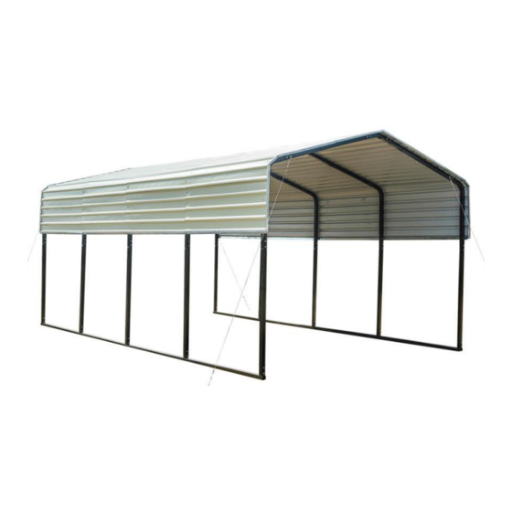
Main Specifications : Overall assembled size : W3.66 x L6 x H2.9 (m) / 12 x 20 x 10 (ft) Width : 3.66 m / 12ft Length : 6 m / 20 ft Ridge Peak Height : 2.9 m / 10 ft ... - Page 3 TMG-CP1220 Part List Parts Graphical Description code Peak arch tube Middle rafter tube Shoulder tube Sidewall tube Short casing Side edge crossbar (front and rear truss) Side edge crossbar (middle truss) Foot tube (front and rear) Foot tube (middle) Metal sheet...
- Page 4 Steel cable mounting plate Anchor Hook ( M14x120mm ) Steel cable(3.3m) Expansion bolt (φ16x150mm) Waterproof silicon sealant Teroson statu Hex bolt M10x60mm Self tapping screw M5x30mm Rivet φ3x6mm Corner protector Sleeve W W W . T M G I N D U S T R I A L . C O M P 3 / 14 T o l l F r e e : 1 - 8 7 7 - 7 6 1 - 2 8 1 9...
- Page 5 Installation steps Step 1 : Review the whole structure and choose the proper installation site Refer to the foundation structure drawing 1, draw lines on the ground for positioning, all dimension lines are drawn from the center of the pipe to the center, and the diagonal X must be equal to Y.
- Page 6 Step 2 : Assemble all trusses The building includes 5 trusses: (1) front truss, (1) rear truss, and (3) middle trusses. Parts used to install the front and rear truss in this step (refer to Figure2): - (1x2) Peak arch tube (#1) - (2x2) Middle rafter tube (#2) - (2x2) Shoulder tube (#3) - (2x2) Sidewall tube (#4)
- Page 7 Parts used to install (3) middle trusses in this step (refer to Figure 3). - (1x3) Peak arch tube (#1) - (2x3) Middle rafter tube (#2) - (2x3) Shoulder tube (#3) - (2x3) Sidewall tube (#4) - (24x3) Hex bolt (#17) - (12x3) Self tapping screw (#18) - (6x3) Short casing (#4A) Figure 3...
- Page 8 Step 3 : Assemble all trusses to the foundation pipe and connect them with (#17) bolts The front and rear trusses are installed with one side of (#12) Steel cable mounting plate facing outwards. (refer to Figure 5) Figure 5 Step 4 : Install the color iron tile ...
- Page 9 Figure 6 Install the first color iron tile. Take the first colored iron tile at the top as the benchmark, ensure that both ends of each colored iron tile are aligned, install as shown in Figure 7, and lock it on the truss with (#18) self tapping screw. (refer to Figure 7) W W W .
- Page 10 Figure 7 Install all color iron tiles in turn, make sure that both ends of each color iron tile are aligned, and apply Waterproof silicon sealant (#16) on the butt joint of both ends (refer to Figure 8) Figure 8 W W W .
- Page 11 Step 5 : Install the front and rear edging strips Start to install the color iron tile edge protector (#9) from one side, and align one end with the color iron tile edge. The opening of the edge banding strip of the color iron tile shall be aligned with the end face of the color iron tile, and the bottom buckle can be pressed into place.
- Page 12 Install the Edge buckle (#10), and the two raised card points of the Edge buckle are aligned with the square holes at the interfaces of the two color iron tile edge bands, and then press the buckle in place. The front and rear installation methods are the same. (refer to Figure 10) Figure 10 Step 6 : Connect the crossbar ...
- Page 13 Figure 11 Step 7 : Install the square pipe waterproof plug and anti-collision angle Put the waterproof plug into the square pipe head. Tear the 3M adhesive protective film on the anti-collision angle, and paste the anti-collision angle to one end of (#5A)side edge crossbar.
- Page 14 Figure 12 Step 8 : Install the wire rope Select a suitable position to fix the expansion bolt of the draw hook on the ground, hook one end of (#14) Steel cable to (#12) Steel cable mounting plate, and fix the other end to (#13) Anchor hook of the draw hook, adjust the nut on the steel wire rope to tighten the steel wire rope (refer to Figure 13).
-
Page 15: After The Installation
Figure 13 Now that your building is completely installed, we need to check all components and trusses to make sure the whole structure is rectangular. Check whether the connection of color steel tile fits. We provide (#19) rivets, which can be used to fix the color steel tiles where necessary, so that they can fit together to prevent water leakage.
Need help?
Do you have a question about the TMG-CP1220 and is the answer not in the manual?
Questions and answers