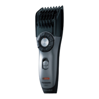
Summary of Contents for Panasonic ER217-E2
-
Page 1: Table Of Contents
ORDER NO. SD0604E33CE AC/Rechargeable Beard/Hair Trimmer ER217-E2 SPECIFICATIONS CONTENTS Page Page 1 SCHEMATIC DIAGRAM 5 TROUBLESHOOTING GUIDE 2 WIRING CONNECTION DIAGRAM 6 EXPLODED VIEW 3 DISASSEMBLY INSTRUCTIONS 7 REPLACEMENT PARTS LIST 4 ASSEMBLY INSTRUCTIONS © 2006 Matsushita Electric Works, Ltd. All rights reserved. -
Page 2: Schematic Diagram
ER217-E2 1 SCHEMATIC DIAGRAM 2 WIRING CONNECTION DIAGRAM... -
Page 3: Disassembly Instructions
ER217-E2 3 DISASSEMBLY INSTRUCTIONS Follow the procedure below to disassemble the main body. 1. Remove the attachment and blade. 2. Loosen a screw and remove the bottom cover. 3. Insert a slotted-head screw driver (less than 2.4mm width on top) into the slit of dial cover and raise it with the driver. - Page 4 ER217-E2 6. To separate the housing C and B, insert a slotted-head screw driver into the slit of housing. Raise the housing C with the driver slightly and open the housings with hand slowly. NOTE: In case of the housings can not be opened, insert the driver further (depth to the lamp cover).
-
Page 5: Assembly Instructions
ER217-E2 4 ASSEMBLY INSTRUCTIONS 1. Insert the rechargeable battery into the battery holder. NOTE: Make sure to attach the washer and O-ring to the battery terminal. The O-ring for the battery terminal is the thickest. Confirm if the O-ring is attached properly. - Page 6 ER217-E2 6. Attach the wire spring and the blade springs with the housing C. NOTE: Make sure to set the wire spring properly. 7. Attach the lack to the housing C with the lowest position. 8. Set the housing C firmly and tighten two screws.
-
Page 7: Troubleshooting Guide
ER217-E2 5 TROUBLESHOOTING GUIDE (Refer to WIRING CONNECTION DIAGRAM) Fig. 1 Fig. 2... -
Page 8: Exploded View
ER217-E2 6 EXPLODED VIEW... -
Page 9: Replacement Parts List
ER217-E2 7 REPLACEMENT PARTS LIST NOTE : *A=available as an optional accessory *B=only available as set *C=available individually Ref.No. Part No. Part Name & Descriptions Remarks Per Unit WER217K7457 COMB ATTACHMENT (BG) WER9602Y BLADE BLOCK WER217S3107 DIAL COVER (BG) WES7023L9008...


Need help?
Do you have a question about the ER217-E2 and is the answer not in the manual?
Questions and answers