Table of Contents
Advertisement
Quick Links
www.ti.com
User's Guide
AM62x SK EVM User's Guide
This technical User's Guide describes the hardware architecture of the AM62x SKEVM, a low cost Starter
Kit built around the AM62x SoC. The AM62x processor comprises of a Quad-Core 64-bit Arm
microprocessor, Single-core Arm Cortex-R5F MCU and an Arm Cortex-M4F MCU.
The SKEVM allows the user to experience great dual display feature through HDMI (over DPI) and LVDS, as
well as industrial communication solutions using serial, Ethernet, USB and other interfaces.
The SKEVM can be used for your display application(for example a HMI or control panel) with either a
HDMI display or an external LVDS panel, up to 2K resolution. It's high performance (up to) Quad-A53 ARM
cores at 1.4GHz, with rich industrial interfaces, offer control and communication capabilities for a wide ranges
of applications, such as PLC, automation control and monitor/supervisor systems. In addition, SKEVM can
communicate with other processors or systems, and act as a communication gateway. The embedded emulation
logic allows for emulation and debugging using standard development tools such as Code Composer Studio™
from TI.
This evaluation board is a pre-production release and has several known issues that should not be
copied into a production system. E1 EVM Shown in product photos.
2 System Description................................................................................................................................................................
Features......................................................................................................................................................................6
2.2 Functional Block Diagram (SK-AM62)...............................................................................................................................
2.4 AM62x SKEVM Interface Mapping...................................................................................................................................
2.5 Power ON/OFF Procedures.............................................................................................................................................
2.6 Peripheral and Major Component Description.................................................................................................................
3 Known Issues and Modifications........................................................................................................................................
SPRUJ40A - MAY 2022 - REVISED FEBRUARY 2023
Submit Document Feedback
ABSTRACT
Note
Table of Contents
Variants................................................................................................................................4
(SK-AM62-P1)..........................................................................................................................9
Copyright © 2023 Texas Instruments Incorporated
Table of Contents
®
®
-Cortex
A53
5
8
11
11
13
64
AM62x SK EVM User's Guide
1
Advertisement
Table of Contents

Related Manuals for Texas Instruments AM62x SK EVM


Summary of Contents for Texas Instruments AM62x SK EVM
-
Page 1: Table Of Contents
Table of Contents User’s Guide AM62x SK EVM User's Guide ABSTRACT This technical User’s Guide describes the hardware architecture of the AM62x SKEVM, a low cost Starter ® ® Kit built around the AM62x SoC. The AM62x processor comprises of a Quad-Core 64-bit Arm -Cortex microprocessor, Single-core Arm Cortex-R5F MCU and an Arm Cortex-M4F MCU. - Page 2 Buttons..............................59 Table 2-28. I2C Mapping Table (SK-AM62 E3 and SK-AM62-P1 Variants)................Table 2-29. I2C Mapping Table (SK-AM62 E2)..........................62 Table 3-1. AM62x SK EVM Known Issues and Modifications....................64 AM62x SK EVM User's Guide SPRUJ40A – MAY 2022 – REVISED FEBRUARY 2023 Submit Document Feedback Copyright ©...
- Page 3 Trademarks Trademarks Sitara ™ is a trademark of Texas Instruments. ® and Cortex ® are registered trademarks of Arm Limited (or its subsidiaries) in the US and/or elsewhere. All trademarks are the property of their respective owners. SPRUJ40A – MAY 2022 – REVISED FEBRUARY 2023...
-
Page 4: Evm Revisions And Assembly Variants
1 EVM Revisions and Assembly Variants The various AM62x SK EVM PCB design revisions, and asssembly variants are listed in the table below. Specific PCB revision is indicated in silkscreen on the PCB. Specific assembly variant is indicated with additional sticker label. -
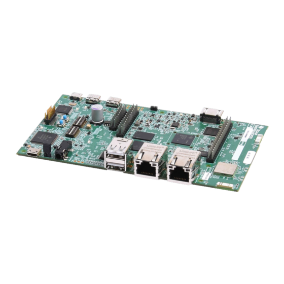
Page 5: System Description
System Description 2 System Description Figure 2-1. SK-AM62 Top View SPRUJ40A – MAY 2022 – REVISED FEBRUARY 2023 AM62x SK EVM User's Guide Submit Document Feedback Copyright © 2023 Texas Instruments Incorporated... -
Page 6: Key Features
2.1.4 Memory • 2GB DDR4 supporting data rate up to 1600MT/s. • Micro SD Card slot with UHS-1 support AM62x SK EVM User's Guide SPRUJ40A – MAY 2022 – REVISED FEBRUARY 2023 Submit Document Feedback Copyright © 2023 Texas Instruments Incorporated... - Page 7 • 16GB eMMC Flash 2.1.5 JTAG/Emulator • XDS110 On-Board Emulator • Supports 20-pin JTAG connection from external emulator SPRUJ40A – MAY 2022 – REVISED FEBRUARY 2023 AM62x SK EVM User's Guide Submit Document Feedback Copyright © 2023 Texas Instruments Incorporated...
-
Page 8: Functional Block Diagram (Sk-Am62)
MCU Header 2.2 Functional Block Diagram (SK-AM62) Figure 2-3 shows the functional block diagram of the AM62x SKEVM Board. AM62x SK EVM User's Guide SPRUJ40A – MAY 2022 – REVISED FEBRUARY 2023 Submit Document Feedback Copyright © 2023 Texas Instruments Incorporated... -
Page 9: Functional Block Diagram (Sk-Am62-P1)
2.3 Functional Block Diagram (SK-AM62-P1) Figure 2-3 shows the functional block diagram of the AM62x SKEVM Board with TPS65219 PMIC. SPRUJ40A – MAY 2022 – REVISED FEBRUARY 2023 AM62x SK EVM User's Guide Submit Document Feedback Copyright © 2023 Texas Instruments Incorporated... -
Page 10: Figure 2-4. Functional Block Diagram Of The Am62X Skevm Board With Tps65219 Pmic
System Description www.ti.com Figure 2-4. Functional Block Diagram of the AM62x SKEVM Board with TPS65219 PMIC AM62x SK EVM User's Guide SPRUJ40A – MAY 2022 – REVISED FEBRUARY 2023 Submit Document Feedback Copyright © 2023 Texas Instruments Incorporated... -
Page 11: Am62X Skevm Interface Mapping
5. Visually inspect that either LD10 or LD12 LED are illuminated. 6. XDS110 JTAG and UART debug console output are routed to micro-USB ports J16 and J15, respectively. SPRUJ40A – MAY 2022 – REVISED FEBRUARY 2023 AM62x SK EVM User's Guide Submit Document Feedback Copyright © 2023 Texas Instruments Incorporated... -
Page 12: Figure 2-5. Sd Bootmode Switch Setting Example (E2, E3)
System Description www.ti.com Figure 2-5. SD Bootmode Switch Setting Example (E2, E3) AM62x SK EVM User's Guide SPRUJ40A – MAY 2022 – REVISED FEBRUARY 2023 Submit Document Feedback Copyright © 2023 Texas Instruments Incorporated... -
Page 13: Peripheral And Major Component Description
C482.1 3.3V 2.6 Peripheral and Major Component Description The following sections provide an overview of the different interfaces and circuits on the AM62x SK EVM. SPRUJ40A – MAY 2022 – REVISED FEBRUARY 2023 AM62x SK EVM User's Guide Submit Document Feedback... -
Page 14: Figure 2-7. Clock Architecture Of Am62X Skevm
There is one external crystal attached to the AM62x SoC to provide clock to the WKUP domain of the SoC (32.768 KHz). Figure 2-8. SoC WKUP Domain AM62x SK EVM User's Guide SPRUJ40A – MAY 2022 – REVISED FEBRUARY 2023 Submit Document Feedback... -
Page 15: Table 2-3. Clock Table
MCU_RESETSTATz is the MCU domain warm reset status output Upon Power on Reset, all peripheral devices connected to the main domain get reset by RESETSTATz. SPRUJ40A – MAY 2022 – REVISED FEBRUARY 2023 AM62x SK EVM User's Guide Submit Document Feedback Copyright © 2023 Texas Instruments Incorporated... -
Page 16: Table 2-4. Display Connector Pinout
Pin no. Signal Pin no. Signal VCC_3V3_SYS(EEPROM_VDD) CH1_LVDS_A2P SoC_I2C0_SCL SoC_I2C0_SDA CH1_LVDS_A3N CH1_LVDS_A3P CH1_LVDS_A0N CH2_LVDS_A0P OLDI_RESETn TS_INT# CH2_LVDS_A1N CH2_LVDS_A1P AM62x SK EVM User's Guide SPRUJ40A – MAY 2022 – REVISED FEBRUARY 2023 Submit Document Feedback Copyright © 2023 Texas Instruments Incorporated... -
Page 17: Table 2-5. Display Connector Pinout (E1/E2)
Connector pin-out. SoC I2C1 signals are also connected to the CSI Header. IO Expander GPIO signals are connected to the camera GPIO’s. SPRUJ40A – MAY 2022 – REVISED FEBRUARY 2023 AM62x SK EVM User's Guide Submit Document Feedback Copyright © 2023 Texas Instruments Incorporated... -
Page 18: Table 2-6. Csi Camera Connector J19 Pin-Out
1x Standard 3.5 mm TRRS Audio Jack connector Mfr. Part# SJ-43514 shall be provided for MIC and Headphone output. Audio Codec’s Line inputs are terminated to Testpoints. AM62x SK EVM User's Guide SPRUJ40A – MAY 2022 – REVISED FEBRUARY 2023 Submit Document Feedback Copyright ©... - Page 19 The HDMI Framer is powered using 3.3 V Board IO Supply and 1.2 V by a dedicated LDO Mfr Part# TLV75512PDQNR. SPRUJ40A – MAY 2022 – REVISED FEBRUARY 2023 AM62x SK EVM User's Guide Submit Document Feedback Copyright © 2023 Texas Instruments Incorporated...
- Page 20 20 Pin JTAG connector is sensed using a presence detect circuit, the mux will be set to route the 20 pin signals from the cTI connector to the AM62x SoC in place of the on-board emulation circuit. AM62x SK EVM User's Guide SPRUJ40A – MAY 2022 – REVISED FEBRUARY 2023 Submit Document Feedback Copyright ©...
-
Page 21: Table 2-7. Jtag Connector (J17) Pin-Out
Table 2-7. JTAG Connector (J17) Pin-out Pin No. Signal JTAG_TMS JTAG_TRST# JTAG_TDI JTAG_TDIS VCC3V3_SYS JTAG_TDO SEL_XDS110_INV JTAG_cTI_RTCK DGND JTAG_cTI_TCK DGND JTAG_EMU0 JTAG_EMU1 JTAG_EMU_RSTn SPRUJ40A – MAY 2022 – REVISED FEBRUARY 2023 AM62x SK EVM User's Guide Submit Document Feedback Copyright © 2023 Texas Instruments Incorporated... - Page 22 SoC and WARM_RESETn for warm reset of the SoC. One Interrupt signal from the Test Automation header is going to the SoC GPIO (MCU_GPIO0_15) for providing an external Interrupt. AM62x SK EVM User's Guide SPRUJ40A – MAY 2022 – REVISED FEBRUARY 2023 Submit Document Feedback Copyright ©...
-
Page 23: Table 2-8. Test Automation Connector (J23) Pin-Out
DGND Power TEST_POWERDOWN Input DGND Power TEST_PORZn Input TEST_WARMRESETn Input TEST_GPIO1 Bidirectional TEST_GPIO2 Bidirectional TEST_GPIO3 Input TEST_GPIO4 Input SPRUJ40A – MAY 2022 – REVISED FEBRUARY 2023 AM62x SK EVM User's Guide Submit Document Feedback Copyright © 2023 Texas Instruments Incorporated... -
Page 24: Table 2-9. Uart Port Interface
Hardware Flow Control as the CTS/RTS pins were re-purposed for other uses. Additionally, UART1 is selectable between the Expansion Connector, the FT4232 (Default) or the Wilink Bluetooth UART. AM62x SK EVM User's Guide SPRUJ40A – MAY 2022 – REVISED FEBRUARY 2023 Submit Document Feedback... - Page 25 Please see Section 3.3 for details on the differences between SK-AM62 E1 and latter implementation of the USB Subsystem. SPRUJ40A – MAY 2022 – REVISED FEBRUARY 2023 AM62x SK EVM User's Guide Submit Document Feedback Copyright © 2023 Texas Instruments Incorporated...
- Page 26 IEC 61000-4-2. The USB HUB is powered by 3.3V from board IO supply and the 1.1V supply from Dedicated LDO Mfr Part# TLV75511PDQNR. AM62x SK EVM User's Guide SPRUJ40A – MAY 2022 – REVISED FEBRUARY 2023 Submit Document Feedback...
- Page 27 Please see Section 3.3 for details on the differences between E1 and latter implementation of the USB Subsystem. SPRUJ40A – MAY 2022 – REVISED FEBRUARY 2023 AM62x SK EVM User's Guide Submit Document Feedback Copyright © 2023 Texas Instruments Incorporated...
- Page 28 DDR4 reset is an active low signal, which is controlled by SoC and the signal is pulled down to set the default active state. A footprint for pull up is also provided. AM62x SK EVM User's Guide SPRUJ40A – MAY 2022 – REVISED FEBRUARY 2023 Submit Document Feedback Copyright ©...
- Page 29 The OSPI interface of the SoC is powered by VDDSHV1 Power group of SoC and is connected to 1.8V IO supply. SPRUJ40A – MAY 2022 – REVISED FEBRUARY 2023 AM62x SK EVM User's Guide Submit Document Feedback Copyright © 2023 Texas Instruments Incorporated...
- Page 30 The eMMC device requires two power supplies, 3.3 V for NAND memory and 1.8 V for the eMMC interface. The MMC0 interface of the SoC is powered by the VDDSHV4 power domain, which is connected to 1.8 V IO supply. AM62x SK EVM User's Guide SPRUJ40A – MAY 2022 – REVISED FEBRUARY 2023 Submit Document Feedback Copyright ©...
- Page 31 TVS diodes providing system-level IEC 61000-4-2 ESD protection, ± 8-kV contact discharge and ± 15kV air-gap discharge. SPRUJ40A – MAY 2022 – REVISED FEBRUARY 2023 AM62x SK EVM User's Guide Submit Document Feedback Copyright © 2023 Texas Instruments Incorporated...
- Page 32 Power supply rails. The MMC2 interface of the SoC is powered by the VDDSHV6 power domain, which is connected to 1.8 V IO supply. AM62x SK EVM User's Guide SPRUJ40A – MAY 2022 – REVISED FEBRUARY 2023 Submit Document Feedback...
- Page 33 The remaining 65277 bytes are available to the user for data or code storage. SPRUJ40A – MAY 2022 – REVISED FEBRUARY 2023 AM62x SK EVM User's Guide Submit Document Feedback Copyright © 2023 Texas Instruments Incorporated...
- Page 34 10/100/1G Connectivity. RJ45 Connectors have integrated magnetics and LEDs for indicating 1000BASE-T link as well as receive or transmit Activity. IO supply to the Ethernet PHY is set 3.3V IO level. AM62x SK EVM User's Guide SPRUJ40A – MAY 2022 – REVISED FEBRUARY 2023 Submit Document Feedback...
- Page 35 CPSW_RGMII2 port of the AM62x SoC is connected to DP83867 whose configuration is as given below: PHY ADDR: 00001 Auto_neg: Enabled ANGsel 10/100/1000 RGMII Clk skew Tx: 0ns SPRUJ40A – MAY 2022 – REVISED FEBRUARY 2023 AM62x SK EVM User's Guide Submit Document Feedback Copyright © 2023 Texas Instruments Incorporated...
-
Page 36: Table 2-10. Io Expander Signal Detail
EXP CONN HAT Board Detection GPIO_AUD_RSTn OUTPUT Audio Codec Reset Control GPIO GPIO_eMMC_RSTn OUTPUT eMMC Reset control GPIO AM62x SK EVM User's Guide SPRUJ40A – MAY 2022 – REVISED FEBRUARY 2023 Submit Document Feedback Copyright © 2023 Texas Instruments Incorporated... - Page 37 UART1_FET_SEL OUTPUT TS_INT# OUTPUT OLDI Display Touch Screen Interrupt IO_EXP_TEST_LED OUTPUT GPIO used to control USED TEST LED SPRUJ40A – MAY 2022 – REVISED FEBRUARY 2023 AM62x SK EVM User's Guide Submit Document Feedback Copyright © 2023 Texas Instruments Incorporated...
-
Page 38: Table 2-11. Gpio Mapping
VDDSHV0 SoC_DVDD3V3 Board Detection P010 PRU Board PRU_DETECT DETECTION IO EXPANDER - P11 INPUT HIGH VDDSHV0 SoC_DVDD3V3 Detection AM62x SK EVM User's Guide SPRUJ40A – MAY 2022 – REVISED FEBRUARY 2023 Submit Document Feedback Copyright © 2023 Texas Instruments Incorporated... - Page 39 VDDSHV0 SoC_DVDD3V3 Backlight Enable User Test LED 2 IO_EXP_TEST_LED GPIO IO EXPANDER - P27 OUTPUT HIGH VDDSHV0 SoC_DVDD3V3 SPRUJ40A – MAY 2022 – REVISED FEBRUARY 2023 AM62x SK EVM User's Guide Submit Document Feedback Copyright © 2023 Texas Instruments Incorporated...
-
Page 40: Table 2-12. Type-C Port Power Roles
Connector 2(J13) - Power role – DRP, Data role – USB2.0 DFP or UFP The AM62x SK EVM supports voltage input ranges of 5 V - 15 V and 3A of current. A USB PD controller Mfr. Part# TPS65988DHRSHR is used for PD negotiation upon cable detection to get necessary power required for the board. - Page 41 LDOs. The 5 V supply generated from the Buck Boost regulator LM34936RHFR is used for powering the onboard peripherals SPRUJ40A – MAY 2022 – REVISED FEBRUARY 2023 AM62x SK EVM User's Guide Submit Document Feedback Copyright © 2023 Texas Instruments Incorporated...
- Page 42 The figure below shows the various discrete regulators and LDOs used to generate power rails and the current consumption of each peripheral on AM62x SKEVM board. AM62x SK EVM User's Guide SPRUJ40A – MAY 2022 – REVISED FEBRUARY 2023 Submit Document Feedback...
- Page 43 System Description SPRUJ40A – MAY 2022 – REVISED FEBRUARY 2023 AM62x SK EVM User's Guide Submit Document Feedback Copyright © 2023 Texas Instruments Incorporated...
- Page 44 The figure below shows the Power Up and Power Down sequence of all the AM62x SKEVM Power supplies. AM62x SoC Power rails are named in red. AM62x SK EVM User's Guide SPRUJ40A – MAY 2022 – REVISED FEBRUARY 2023 Submit Document Feedback...
- Page 45 System Description SPRUJ40A – MAY 2022 – REVISED FEBRUARY 2023 AM62x SK EVM User's Guide Submit Document Feedback Copyright © 2023 Texas Instruments Incorporated...
- Page 46 System Description www.ti.com AM62x SK EVM User's Guide SPRUJ40A – MAY 2022 – REVISED FEBRUARY 2023 Submit Document Feedback Copyright © 2023 Texas Instruments Incorporated...
- Page 47 System Description SPRUJ40A – MAY 2022 – REVISED FEBRUARY 2023 AM62x SK EVM User's Guide Submit Document Feedback Copyright © 2023 Texas Instruments Incorporated...
-
Page 48: Table 2-14. Soc Power Supply
VCC_1V8 SoC_DVDD1V8 0x4B 10mΩ ± 1% VDDA1V8 VDDA_1V8 0x4E 10mΩ ± 1% VCC1V2_DDR VDD_DDR4 0x46 10mΩ ± 1% AM62x SK EVM User's Guide SPRUJ40A – MAY 2022 – REVISED FEBRUARY 2023 Submit Document Feedback Copyright © 2023 Texas Instruments Incorporated... -
Page 49: Table 2-16. Ina I2C Device Address (E2)
Note that OFF setting provides a low logic level (‘0’) and an ON setting provides a high logic level (‘1’). Note The boot mode orientation has changed between E1 and future revisions. Please follow board silkscreen. SPRUJ40A – MAY 2022 – REVISED FEBRUARY 2023 AM62x SK EVM User's Guide Submit Document Feedback Copyright © 2023 Texas Instruments Incorporated... -
Page 50: Figure 2-9. Bootmode Switch Configuration For Sd Boot (E2, E3)
System Description www.ti.com Figure 2-9. Bootmode Switch Configuration for SD Boot (E2, E3) AM62x SK EVM User's Guide SPRUJ40A – MAY 2022 – REVISED FEBRUARY 2023 Submit Document Feedback Copyright © 2023 Texas Instruments Incorporated... -
Page 51: Figure 2-10. Bootmode Switch Configuration For Sd Boot (E1)
Table 2-18. PLL Reference Clock Selection BOOTMODE [2:0] Bit 2 Bit 1 Bit 0 PLL REF CLK (MHz) RSVD RSVD RSVD SPRUJ40A – MAY 2022 – REVISED FEBRUARY 2023 AM62x SK EVM User's Guide Submit Document Feedback Copyright © 2023 Texas Instruments Incorporated... -
Page 52: Table 2-19. Boot Device Selection Boot-Mode [6:3]
Boot Device Reserved Read Mode 2 Read Mode 1 Serial NAND Speed Iclk Csel OSPI Reserved Iclk Csel QSPI AM62x SK EVM User's Guide SPRUJ40A – MAY 2022 – REVISED FEBRUARY 2023 Submit Document Feedback Copyright © 2023 Texas Instruments Incorporated... -
Page 53: Table 2-22. Backup Boot Media Configuration Boot-Mode
PWR and Ground reference. INTn signal from PRU Header is wired along with the CPSW PHY interrupts and connected to the EXTINTn pin of the SoC. SPRUJ40A – MAY 2022 – REVISED FEBRUARY 2023 AM62x SK EVM User's Guide Submit Document Feedback Copyright © 2023 Texas Instruments Incorporated... -
Page 54: Table 2-24. Pru Header (J10) Pin-Out
GPMC0_AD1/ PR0_PRU1_GPO9/ PR0_PRU1_GPI9/ MCASP2_AXR5/ PR0_PRU0_GPO1/ PR0_PRU0_GPO1 PR0_PRU0_GPI1/ TRC_CTL/ GPIO0_16/ DDR0_IO_PLL_REFCLK_TEST0P/ DDR0_IO_PLL_REFCLK_TEST1P/ GPIO1_113/ LED_DIO1 GPMC0_AD2/ PR0_PRU1_GPO10/ PR0_PRU1_GPI10/ MCASP2_AXR6/ PR0_PRU0_GPO2 PR0_PRU0_GPO2/ PR0_PRU0_GPI2/ TRC_DATA0/ GPIO0_17 AM62x SK EVM User's Guide SPRUJ40A – MAY 2022 – REVISED FEBRUARY 2023 Submit Document Feedback Copyright © 2023 Texas Instruments Incorporated... -
Page 55: Table 2-25. 40 Pin User Expansion Connector
GPIO1_25/ MCASP2_AXR1/ EHRPWM_TZn_IN4 DGND UART5_RXD/ TIMER_IO2/ SYNC2_OUT/ EXP_UART5_RXD UART1_DTRn/ EQEP2_I/ PR0_UART0_RXD/ GPIO1_24/ MCASP2_AXR0/ EHRPWM_TZn_IN3 MCASP0_ACLKX/ SPI2_CS1/ EXP_SPI2_CS1 ECAP2_IN_APWM_OUT/ GPIO1_11/ EQEP1_A SPRUJ40A – MAY 2022 – REVISED FEBRUARY 2023 AM62x SK EVM User's Guide Submit Document Feedback Copyright © 2023 Texas Instruments Incorporated... - Page 56 GPMC0_DIR/ PR0_ECAP0_IN_APWM_OUT/ EXP_GPIO0_40/ MCASP2_AXR13/ PR0_PRU0_GPO16/ PR0_ECAP0_IN_APWM_OUT PR0_PRU0_GPI16/ TRC_DATA14/ GPIO0_40/ EQEP2_S MCASP0_AXR0/ PR0_ECAP0_IN_APWM_OUT/ EXP_EHRPWM1_B AUDIO_EXT_REFCLK0/ PR0_UART0_TXD/ EHRPWM1_B/ GPIO1_10/ EQEP0_I DGND AM62x SK EVM User's Guide SPRUJ40A – MAY 2022 – REVISED FEBRUARY 2023 Submit Document Feedback Copyright © 2023 Texas Instruments Incorporated...
-
Page 57: Table 2-26. Pin Mcu Connector (J9)
Allowed current limit is 100 mA on 3.3 V rail. Table 2-26. Pin MCU Connector (J9) Pin No. SoC Ball No. Net Name Pin Multiplexed Signal VCC_3V3_SYS SPRUJ40A – MAY 2022 – REVISED FEBRUARY 2023 AM62x SK EVM User's Guide Submit Document Feedback Copyright © 2023 Texas Instruments Incorporated... - Page 58 MCU_I2C0_SDA MCU_GPIO0_18 MCU_MCAN0_RX/ MCU_TIMER_IO0/ MCU_MCAN0_RX MCU_SPI1_CS3/ MCU_GPIO0_14 MCU_RESETSTATz/ MCU_RESETSTATz MCU_GPIO0_21 MCU_I2C0_SCL/ MCU_I2C0_SCL MCU_GPIO0_17 CONN_MCU_RESETz MCU_RESETz MCU_SAFETY_ERRORz_3V3 MCU_ERRORN DGND AM62x SK EVM User's Guide SPRUJ40A – MAY 2022 – REVISED FEBRUARY 2023 Submit Document Feedback Copyright © 2023 Texas Instruments Incorporated...
-
Page 59: Table 2-27. Evm Push Buttons
The images below depict the I2C tree and the tables provide the complete I2C address mapping details on AM62x SKEVM. SPRUJ40A – MAY 2022 – REVISED FEBRUARY 2023 AM62x SK EVM User's Guide Submit Document Feedback Copyright © 2023 Texas Instruments Incorporated... -
Page 60: Table 2-28. I2C Mapping Table (Sk-Am62 E3 And Sk-Am62-P1 Variants)
I2C Port Device/Function Part No. I2C Address SoC_I2C0 Board ID EEPROM AT24C512C-MAHM-T 0x51 SoC_I2C0 User Expansion Connector <connector interface> AM62x SK EVM User's Guide SPRUJ40A – MAY 2022 – REVISED FEBRUARY 2023 Submit Document Feedback Copyright © 2023 Texas Instruments Incorporated... - Page 61 WKUP_I2C0 LED Driver TPIC2810D 0x60 Others BOOTMODE_I2C I2C Bootmode Buffer TCA6424ARGJR 0x22 BOOTMODE_I2C Test Automation Header <connector interface> SPRUJ40A – MAY 2022 – REVISED FEBRUARY 2023 AM62x SK EVM User's Guide Submit Document Feedback Copyright © 2023 Texas Instruments Incorporated...
- Page 62 I2C Port Device/Function Part No. I2C Address SoC_I2C0 Board ID EEPROM AT24C512C-MAHM-T 0x51 SoC_I2C0 User Expansion Connector <connector interface> AM62x SK EVM User's Guide SPRUJ40A – MAY 2022 – REVISED FEBRUARY 2023 Submit Document Feedback Copyright © 2023 Texas Instruments Incorporated...
-
Page 63: Table 2-29. I2C Mapping Table (Sk-Am62 E2)
WKUP_I2C0 LED Driver TPIC2810D 0x60 Others BOOTMODE_I2C I2C Bootmode Buffer TCA6424ARGJR 0x22 BOOTMODE_I2C Test Automation Header <connector interface> SPRUJ40A – MAY 2022 – REVISED FEBRUARY 2023 AM62x SK EVM User's Guide Submit Document Feedback Copyright © 2023 Texas Instruments Incorporated... -
Page 64: Known Issues And Modifications
Applicable EVM Revisions: E1 Issue Description: On revision E1 of the AM62x SK EVM, the J9 and J10 are missaligned by one set of pins, meaning that boards designed for other Sitara SK EVMs that mate to both the MCU and PRU headers will not fit on this revision. -
Page 65: Issue 3 - Usb Boot Descoped On E1
Tx Clock skew should be set to 0ns as AM62x MAC always has internal delay enabled for Tx. Rx Clock Skew should remain 2ns. SPRUJ40A – MAY 2022 – REVISED FEBRUARY 2023 AM62x SK EVM User's Guide Submit Document Feedback Copyright © 2023 Texas Instruments Incorporated... -
Page 66: Issue 7 - Test_Powerdown
TCA9517DR which does not have the same incomaptibiltiy. SK-AM62-P1 E2 and newer boards feature this change. If the IC is replaced, pullups on the B side should be preserved. AM62x SK EVM User's Guide SPRUJ40A – MAY 2022 – REVISED FEBRUARY 2023 Submit Document Feedback Copyright ©... -
Page 67: Figure 3-2. Schematic Of I2C Buffer Section
Known Issues and Modifications Figure 3-2. Schematic of I2C Buffer Section Figure 3-3. Location on AM62x SK E3 (Bottom Side) SPRUJ40A – MAY 2022 – REVISED FEBRUARY 2023 AM62x SK EVM User's Guide Submit Document Feedback Copyright © 2023 Texas Instruments Incorporated... -
Page 68: Regulatory Compliance
Regulatory Compliance www.ti.com Regulatory Compliance Hereby, Texas Instruments declares that the radio equipment, "AM62x Starter Kit for the Sitara Processors" is in compliance with directive 2014/53/EU. The full text of the EU declaration of confirmity is available in the following website. - Page 69 TI products. TI’s provision of these resources does not expand or otherwise alter TI’s applicable warranties or warranty disclaimers for TI products. TI objects to and rejects any additional or different terms you may have proposed. IMPORTANT NOTICE Mailing Address: Texas Instruments, Post Office Box 655303, Dallas, Texas 75265 Copyright © 2023, Texas Instruments Incorporated...
Need help?
Do you have a question about the AM62x SK EVM and is the answer not in the manual?
Questions and answers