Table of Contents
Advertisement
Quick Links
INSTALLATION, OPERATION, AND MAINTENANCE MANUAL
Table of Contents
1
SCOPE ......................................................................................................................................................................................... 3
2
PRODUCT DESCRIPTION AND FEATURES ..................................................................................................................................... 3
3
CAUTIONS AND WARNINGS ........................................................................................................................................................ 4
4
VALVE IDENTIFICATION ............................................................................................................................................................... 4
5
VALVE COMPONENTS ................................................................................................................................................................. 4
6
ACCESSORIES .............................................................................................................................................................................. 6
6.1
...................................................................................................................................................................................... 6
6.2
................................................................................................................................................................................. 6
6.3
........................................................................................................................................................................................... 7
7
FACTORY TESTING ....................................................................................................................................................................... 8
8
STORAGE, HANDLING, AND INSTALLATION ................................................................................................................................. 9
8.1
........................................................................................................................................................................................... 9
8.2
......................................................................................................................................................................................... 9
8.3
..................................................................................................................................................................................... 9
8.3.1
General Notes on Installation ............................................................................................................................................... 9
8.3.2
Screwed End Valves ............................................................................................................................................................... 9
8.3.3
Socket Weld End Valves ...................................................................................................................................................... 10
8.3.4
Flanged End Valves ............................................................................................................................................................. 10
8.3.5
Butt Weld End Valves .......................................................................................................................................................... 11
8.3.6
Butt Weld End X Flange End Valves .................................................................................................................................... 11
9
OPERATION ............................................................................................................................................................................... 12
9.1
V
9.2
.......................................................................................................................................................................... 12
9.3
.............................................................................................................................................................................. 12
9.4
................................................................................................................................................................................ 13
10
REPAIR SERVICE ........................................................................................................................................................................ 13
10.1.1
Clearing Internal Debris .................................................................................................................................................. 13
10.1.2
Body and Wedge Seating ............................................................................................................................................... 13
10.2.1
Packing Shim Installation Under Pressure ...................................................................................................................... 14
10.2.2
Repacking a Valve with Zero Pressure ............................................................................................................................ 15
10.3.1
Sealing a Bonnet Leak with Zero Pressure ...................................................................................................................... 18
10.3.2
Sealing a Bonnet Leak Under Pressure ........................................................................................................................... 18
................................................................................................................................................................................. 22
10.4.1
Valve Operation with Broken Stem ................................................................................................................................ 22
10.4.2
Stem Repair .................................................................................................................................................................... 22
APPENDIX A: BROKEN BOLT REMOVAL .............................................................................................................................................. 24
APPENDIX B: BONNET SCREW TIGHTENING PROCEDURE ................................................................................................................... 26
APPENDIX C: MODEL-1 - NPS 1 AND 1 ¼ BOLT REPLACEMENT FIXTURE FOR FIELD SERVICE REPAIR .................................................. 28
KEROTEST CUSTOMER
MODEL-1 GATE VALVE
INSTALLATION, OPERATION, AND
MAINTENANCE MANUAL
KEROTEST CUSTOMER MODEL-1 GATE VALVE
............................................................................................................................................................... 12
.................................................................................................................................................................... 13
............................................................................................................................................................ 14
............................................................................................................................................................. 18
................................................................................................................................................. 23
................................................................................................................................................................. 24
.......................................................................................................................................................... 24
: ......................................................................................................................................................... 26
: ...................................................................................................................................................... 26
NO.: K-1464
REV.: 11
DATE: 06/26/2018
PAGE: 1 OF 30
Advertisement
Table of Contents

Related Manuals for Kerotest MODEL-1


Summary of Contents for Kerotest MODEL-1
-
Page 1: Table Of Contents
ROCEDURE APPENDIX B: BONNET SCREW TIGHTENING PROCEDURE ........................26 : ................................. 26 NCREMENTAL IGHTENING ROCEDURE : ..............................26 ROSS ATTERN IGHTENING EQUENCES APPENDIX C: MODEL-1 – NPS 1 AND 1 ¼ BOLT REPLACEMENT FIXTURE FOR FIELD SERVICE REPAIR ..........28... - Page 2 NO.: K-1464 KEROTEST CUSTOMER REV.: 11 MODEL-1 GATE VALVE INSTALLATION, OPERATION, AND DATE: 06/26/2018 MAINTENANCE MANUAL PAGE: 2 OF 30 Table of Tables Table 1: Valve Specifications ................................5 Table 2: Handwheel Options ................................6 Table 3: Minimum Test Parameters ..............................8 Table 4: Valve Torque Values ................................
-
Page 3: Scope
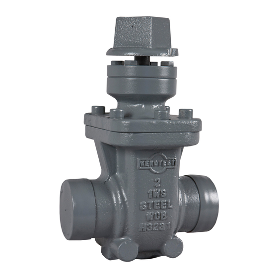
This operations manual defines for gas utility customers the procedures for proper use and common repairs on the Model 1 line of metal seat gate valves. 2 PRODUCT DESCRIPTION AND FEATURES Below are some of the features of the Kerotest Model-1 steel gate valves: Maintenance free No gland tightening ... -
Page 4: Cautions And Warnings
Name of the product line 5 VALVE COMPONENTS Model-1 Valves are divided into 2 basic designs: (1) Prior to 1988 production date and (2) after 1988 production date. Valves produced after 1988 contain a weather seal O-ring. Figure 3 shows the part differences between the two versions. -
Page 5: Table 1: Valve Specifications
NO.: K-1464 KEROTEST CUSTOMER REV.: 11 MODEL-1 GATE VALVE INSTALLATION, OPERATION, AND DATE: 06/26/2018 MAINTENANCE MANUAL PAGE: 5 OF 30 Table 1: Valve Specifications Valve C/L to Number of Size Turns to (in) Open/Close 7.25 1-1/4 7.25 8.75 10.43 10.3 12.68... -
Page 6: Accessories
72537699 Locking Device Model-1 valves can be ordered with a locking device installed or it may be installed by customers. This locking device prevents unauthorized users from changing the valve state (open or close) with a customer supplied lock. When installed, the lock and/or the cap may turn, but no torque is applied to the stem. -
Page 7: Coating
Figure 4: Locking Device Coating The Model-1 valve is ordered with either a zinc chromate gray primer coating or a two- component, high solids green epoxy coating. The gray primer will provide a limited indoor non-exposed protection against corrosion. It is the responsibility of the customer to provide long duration corrosion protection coverings or systems once installed per CFR 192 Subpart I. -
Page 8: Factory Testing
NO.: K-1464 KEROTEST CUSTOMER REV.: 11 MODEL-1 GATE VALVE INSTALLATION, OPERATION, AND DATE: 06/26/2018 MAINTENANCE MANUAL PAGE: 8 OF 30 7 FACTORY TESTING To be certain that all valves shipped from the factory are bubble tight, they are subjected to the following tests. -
Page 9: Storage, Handling, And Installation
For heavy large valves, use rated lifting slings or straps. The valve or valve assembly must not be lifted by the operating square or handwheel. Most Model-1 valves with the operating square facing up are top-heavy and can shift or rotate in the sling. -
Page 10: Socket Weld End Valves
Standard end flange facing is 1/16" raised face with phonographic finish. Some valves may be ordered with a flat face finish. Contact Kerotest or your distributor for further information and availability of flat face finished valves. Flat face finished valves are slightly shorter than standard faced valves, as allowed per ASME B16.10. -
Page 11: Butt Weld End Valves
NO.: K-1464 KEROTEST CUSTOMER REV.: 11 MODEL-1 GATE VALVE INSTALLATION, OPERATION, AND DATE: 06/26/2018 MAINTENANCE MANUAL PAGE: 11 OF 30 Figure 5: Bolt Torquing Pattern Examples 8.3.5 Butt Weld End Valves NOTE: in order that the valve seats are not affected during the welding operation, the wedge should be in the closed position. -
Page 12: Operation
NO.: K-1464 KEROTEST CUSTOMER REV.: 11 MODEL-1 GATE VALVE INSTALLATION, OPERATION, AND DATE: 06/26/2018 MAINTENANCE MANUAL PAGE: 12 OF 30 9 OPERATION General Valve Operation Standard valves are equipped with a 2” operating square and can be operated with an adaptor tool or wrench. -
Page 13: Pressure Drop
Table 1 count the number of turns to close until it stops. If the turn count is less than the table, then there may be an obstruction. Follow the instructions in 10.1.1, otherwise, follow 10.1.2. If these steps do not correct the problem, contact Kerotest. 10.1.1 Clearing Internal Debris If valves are in the open position in a pipeline for a period of time, there is a chance that sediment or dirt may collect inside the valve. -
Page 14: External Stem Packing Leak
Note: Repairs should only be made using Kerotest repair parts as listed in Table 7, Table 11, or Table 12. A diagram of valve parts is shown in Figure 6. All-thread information by valve size is shown in Table 8. -
Page 15: Repacking A Valve With Zero Pressure
10.2.1 may be repeated a few times and more shims added. If the leak remains, contact Kerotest for support in servicing the valve as described at the beginning of this section. 10.2.2 Repacking a Valve with Zero Pressure This procedure requires a repair kit available from Kerotest. -
Page 16: Table 6: Gland Cap Screw Torque Values
NO.: K-1464 KEROTEST CUSTOMER REV.: 11 MODEL-1 GATE VALVE INSTALLATION, OPERATION, AND DATE: 06/26/2018 MAINTENANCE MANUAL PAGE: 16 OF 30 Table 6: Gland Cap Screw Torque Values Valve Size Torque (ft-lbs) 15 – 20 15 – 20 1-1/4 20 – 30 20 –... -
Page 17: Table 8: Packing Repair All-Thread Studs
NO.: K-1464 KEROTEST CUSTOMER REV.: 11 MODEL-1 GATE VALVE INSTALLATION, OPERATION, AND DATE: 06/26/2018 MAINTENANCE MANUAL PAGE: 17 OF 30 Figure 6: Valve Packing Components Table 8: Packing Repair All-Thread Studs Valve Size All-Thread All-Thread Stud Length Stud and Nut Size (inches minimum) 5/16 –... -
Page 18: External Bonnet Seal Leak
For valve sizes NPS 2 to 6 it is strongly recommended that support clamps be used during bolt replacement. For valve sizes NPS 8 to 12, there is a support clamp available but it is not required. These clamps are available from Kerotest, see Table 9 for associated part numbers. -
Page 19: Table 9: Bolt Replacement Support Clamps
NO.: K-1464 KEROTEST CUSTOMER REV.: 11 MODEL-1 GATE VALVE INSTALLATION, OPERATION, AND DATE: 06/26/2018 MAINTENANCE MANUAL PAGE: 19 OF 30 Table 9: Bolt Replacement Support Clamps Clamp Part Number Compatible Valve Sizes 2” and 3” 72544794 4” and 6” 72544802 8”, 10”, and 12”... -
Page 20: Figure 8: Teflon Rope Installation Diagram
After replacing all of the existing bonnet bolts if the leakage has stopped the repair is complete and the valve is ready for service. If the leakage continues, contact Kerotest for support in servicing the valve. Figure 9: All-Thread Installation Diagram... -
Page 21: Table 11: Bonnet Gaskets
NO.: K-1464 KEROTEST CUSTOMER REV.: 11 MODEL-1 GATE VALVE INSTALLATION, OPERATION, AND DATE: 06/26/2018 MAINTENANCE MANUAL PAGE: 21 OF 30 Table 11: Bonnet Gaskets Part Description Number 1/4" PTFE ROPE 1 FT 1 FT 1.5 FT 2 FT 2 FT 2.5 FT... -
Page 22: Broken Stems
10.4.2 Stem Repair A service pack is available from Kerotest Manufacturing that provides all parts and tools needed to perform this repair. See Figure 10 for a diagram of this repair assembly, and Table 13 for the repair kit part numbers listed by valve size. -
Page 23: Service Parts Ordering Procedure
NO.: K-1464 KEROTEST CUSTOMER REV.: 11 MODEL-1 GATE VALVE INSTALLATION, OPERATION, AND DATE: 06/26/2018 MAINTENANCE MANUAL PAGE: 23 OF 30 Figure 10: Broken Stem Repair Table 13: Broken Stem Repair Kit Part Numbers Part Number Description 72546394 STEM REPAIR KIT... -
Page 24: Appendix A: Broken Bolt Removal
Secure bonnet to body with the appropriate clamps listed in Table 9. If replacing bolts on an NPS 1 or 1-1/4 valve, use the procedure in APPENDIX C: MODEL-1 – NPS 1 AND 1 ¼ BOLT REPLACEMENT FIXTURE FOR FIELD SERVICE REPAIR Spray penetrating oil (not provided) on bolt surface. -
Page 25: Table 14: Bonnet Bolt Removal Chart
1-1/4 7/64" 2 through 6 3/16" 1/4" 10 and 12 *17/64" *Not included in Model-1 Bolt Repair Tool Kit. Table 15: 72631146 Repair Kit Components Description BONNET BOLT REMOVAL GUIDE CHART TOOL,PUNCH,3/16” TOOL,#3 EASY OUT SCREW EXTRACTOR TOOL,CENTER,PUNCH TOOL,#2 EASY OUT SCREW EXTRACTOR TOOL,#4 EASY OUT SCREW EXTRACTOR TOOL,DRILL,3/16”,COBALT,TIN... -
Page 26: Appendix B: Bonnet Screw Tightening Procedure
NO.: K-1464 KEROTEST CUSTOMER REV.: 11 MODEL-1 GATE VALVE INSTALLATION, OPERATION, AND DATE: 06/26/2018 MAINTENANCE MANUAL PAGE: 26 OF 30 APPENDIX B: BONNET SCREW TIGHTENING PROCEDURE When tightening the bonnet screws or all-thread and nuts, use an incremental torque tightening procedure in the cross-pattern outlined below (taken from ASME PCC-1 –... -
Page 27: Figure 12: Example Pattern For 12-Bolt Tightening Sequence
NO.: K-1464 KEROTEST CUSTOMER REV.: 11 MODEL-1 GATE VALVE INSTALLATION, OPERATION, AND DATE: 06/26/2018 MAINTENANCE MANUAL PAGE: 27 OF 30 Figure 12: Example Pattern for 12-Bolt Tightening Sequence... -
Page 28: Appendix C: Model-1 - Nps 1 And 1 ¼ Bolt Replacement Fixture For Field Service Repair
DATE: 06/26/2018 MAINTENANCE MANUAL PAGE: 28 OF 30 APPENDIX C: MODEL-1 – NPS 1 AND 1 ¼ BOLT REPLACEMENT FIXTURE FOR FIELD SERVICE REPAIR Figure 13: Bolt Replacement Instructions (1 of 2) The Figure references in the text of Figure 13 refer to the internal figure numbers in this document’s... -
Page 29: Figure 14: Bolt Replacement Instructions (2 Of 2)
NO.: K-1464 KEROTEST CUSTOMER REV.: 11 MODEL-1 GATE VALVE INSTALLATION, OPERATION, AND DATE: 06/26/2018 MAINTENANCE MANUAL PAGE: 29 OF 30 Figure 14: Bolt Replacement Instructions (2 of 2) - Page 30 Initial Release EAN S-1418 Kerotest Manufacturing Corp. 5500 Second Avenue Pittsburgh, PA 15207 Telephone: (412) 521-4200 www.kerotest.com sales@kerotest.com Prior Document Releases This procedure was previously distributed as “Kerotest Model-1 Gate Valve Operations Manual”. Date Description 12/15/1988 11/28/1990 09/04/1991 07/16/1993 03/28/1996...
Need help?
Do you have a question about the MODEL-1 and is the answer not in the manual?
Questions and answers