Table of Contents
Advertisement
Advertisement
Table of Contents

Related Manuals for Novation nio 2/4

Summary of Contents for Novation nio 2/4
- Page 1 FA0163-01...
-
Page 2: Getting Started
Getting Started Guide in the box and the nio Tutorial movies on the Novation website. If you are having difficulty operating nio and cannot find the solution in this guide, go to the online answerbase at www.novationmusic.com and type any relevant keywords into the search box. -
Page 3: Front Panel Controls
MAC SETUP 1. Close all running applications 2. With nio disconnected from your computer, locate the nio Mac installer on the resources disc and double-click to run it 3. You may be asked to restart your computer to complete installation 4. -
Page 4: Rear Panel Connectors
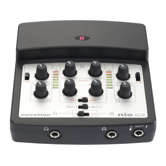
FRONT PANEL CONNECTORS 1. Headphones 1 1/4” jack output 2. Headphones 2 1/4” jack output 3. Mic or instrument 1/4” jack input (can be used to connect a guitar or bass directly). The input source (mic/guitar) is set using the Input 2 Selection switch on the right side of nio SIDE PANEL SWITCHES 1. - Page 5 The USB bus will supply power to the interface so, a few seconds after connecting, the Novation logo on the front of the hardware will light and the interface will be ready to use. Providing the installer has been run, you can now open up an audio application and select nio as the audio input and/or output device in the software preferences.
- Page 6 SENDING AUDIO TO NIO FROM YOUR RECORDING OR DJING SOFTWARE – WHAT ARE SIGNALS A AND B? Once nio has been installed and is then connected, the hardware will show up as nio Audio Inputs 1 and 2, as well as nio Audio Outputs 1-4 within your music software.
- Page 7 RECORDING TO YOUR MUSIC SOFTWARE USING NIO WITH… …ONE OR TWO MICROPHONES Jack Inputs 1 and 2 can both be used to record a microphone source. Input 1 uses the XLR connector on the rear panel, whilst Input 2 uses the 1/4" Jack connector on the front of the interface. Only Input 1 can supply phantom power to a microphone, such as a condenser mic.
- Page 8 If you are recording two vocalists, then you will probably want the ‘input’ switch in the ‘monitor’ section to be set to ‘mono’, to ensure that both vocalists are panned centrally in the headphones. For more information about the monitoring options available for this setup, such as how to send a mix of inputs and backing tracks to a vocalist’s headphones, read the ‘Direct Mix Monitoring’...
- Page 9 If recording and monitoring a stereo source, the ‘input’ switch in the ‘monitor’ section should to be set to ‘stereo’, to ensure that the inputs are panned left and right in the headphones or over the monitors. For more information about the monitoring options available for this setup, such as how to send a mix of inputs and backing tracks to a turntablist’s headphones, read the ‘Direct Mix Monitoring’...
- Page 10 If the musician wants to hear the instrument in their headphones, you will probably want the ‘input’ switch in the ‘monitor’ section to be set to ‘mono’, to ensure that the instrument is panned centrally. For more information about the monitoring options available for this setup, such as how to send a mix of inputs and backing tracks to a musician’s headphones, read the ‘Direct Mix Monitoring’...
- Page 11 Pans inputs 1 and 2 left and right respectively (stereo) or both centrally (mono) MIXING OUTPUTS/PLAYBACK TRACKS (A AND B) If wanting to send playback (recorded) tracks alone to the monitor mix then both dials should be used. The dial on the right should first be set in the extreme anticlockwise position (so that no inputs are heard).
- Page 12 MIXING INPUTS AND OUTPUTS A mix of both inputs and playback tracks can be sent to the monitor mix by using the dial on the right to blend between the two. As listed above, with the dial in the extreme anticlockwise position, only the mix of playback tracks/outputs (a and/or b) are heard, whereas the extreme clockwise position produces only inputs.
- Page 13 13. LED goes green when a sufficient input signal is received 14. Turns the effect on/off – click once with the mouse 1. Novation logo will light once the interface has been connected and a window will appear to confirm successful connection 2.
- Page 14 SAVING/LOADING SOFTWARE SETTINGS Click here to save/load FX Rack Global Presets Once you have created an arrangement of effects, you can save it as a Global Preset by clicking on the box below ‘nio FX Rack’ in the top left corner, as shown in the diagram above. This will activate a menu where you can click ‘Save As…’ to open a window allowing a name to be typed in.
- Page 15 Music Software Computer CLASSIC NOVATION EFFECTS SUPERNOVA II CHORUS This effect was originally designed to simulate the sound of many people singing together (hence the name ‘chorus’). Chorus is an effect produced by mixing a continuously delayed version of the audio signal back with the original. The timing of the delayed version is very small and is controlled by an LFO.
- Page 16 DEPTH Knob - Controls the amplitude of the LFO, which affects the amount of time variation that the delayed signal undergoes CENTRE Knob – Controls the separation between right and left channels, within the limits set by depth. The effect of the dial is much more noticeable at higher values of feedback and depth, and could be described as a ‘feedback spectrum modifier’...
- Page 17 TAP Button – Allows the delay to be synchronised to a beat. Clicking four times on the box (whilst following a beat) sets a delay time based on the timing between clicks MIX Knob – Blends between the fully dry signal (with no delay) in the anticlockwise position and fully wet signal (just delay) in the clockwise position SUPERNOVA II PHASER A Phaser works in a similar way to a chorus effect, only rather than modulating the delay of the original sound, it modulates...
- Page 18 The controls are: INPUT Knob – Increases or decreases the level of the signal at the filter input. No gain modification occurs with the knob in a central position. Rotate clockwise to increase and anticlockwise to decrease the level by up to 18dB TYPE Section –...
- Page 19 The controls are: DEPTH Knob – Sets the amplitude of the modulating sine wave, e.g. how much the gain of the signal is modulated. Rotate clockwise to increase SPEED Knob – Sets the frequency (or speed) of the modulating sine wave, e.g. how quickly the gain is modulated. Rotate clockwise to increase PHASE Knob –...
- Page 20 TWEED TWIN BASS Knob – Defines the amount of low frequency MIDDLE Knob – Defines the amount of mid frequency (presence) TREBLE Knob – Defines the amount of high frequency (brightness) VOLUME Knob – Sets the level US MODERN VALVE GAIN Knob –...
- Page 21 DISTORTION/OVERDRIVE PEDALS 70s FUZZ VOLUME Knob – Sets the volume FUZZ Knob – Sets the amount of distortion DISTORTER TONE Knob – Acts in the same way as the filter knob on other effects; rotating in a clockwise direction filters out bass and rotating in an anticlockwise direction removes high frequency.
- Page 22 FOCUSRITE EFFECTS COMPRESSOR The nio Compressor is modelled on the legendary Focusrite hardware devices, with individually tuned optos to help create the sound of vintage 1960s compression. The plug-in can be used to squash the dynamics of a sound in varying degrees, e.g.
- Page 23 Equalisation of sound is an essential part of the recording process, necessary to remove or boost various sections of the audible frequency spectrum. The nio EQ is 4-band, with 2 fully parametric mid bands and the option of shelving or high-/low- pass on bands 1 and 4, and exhibits the same curves as the classic Focusrite EQ;...
- Page 24 The controls are: THRESHOLD Knob – Sets the level at which the gate closes/opens from 0dB (maximum signal level) to -80dB (80dB below clipping level). Rotate clockwise to raise the threshold. The higher the threshold, the more the signal is affected as the gate closes when the signal falls below the threshold.
- Page 25 Right 1: Right channel (Input 2) gates the left channel (Input 1) – hear only the left channel (Input 1) Right 1 Input 1 Input 2 Right 2: Right channel (Input 2) gates the left channel (Input 1) – hear both sides Right 2 Input 1 Input 2...
- Page 26 N I I O O E E F F F F E E C C T T S S HOT TUNA Hot Tuna is an effect that allows you to tune an instrument connected to a nio input. There are no controls available, only displays.
- Page 27 EXAMPLE SETUP DIAGRAMS 1. PERFORMING GUITAR USING DIRECT FX AND WITH BACKING TRACKS Backing tracks O/P 1/2 I/P 1/2 I/P 1/2 Music Software Computer * This audio stream still appears Set the Rack as ‘inputs’ in the monitoring section of the hardware. It only uses the input to Input 2 b stream within the computer.
- Page 28 In this setup, the ‘b’ stream is inactive (it is used for the guitar’s direct monitor path from the rack to the hardware) so nio outputs 3/4 from your music software (normally b) cannot be used to route audio to connected speakers or headphones. Additionally, input 2 cannot be used to record a separate source (without FX) in this setup because nio inputs 1/2 in the music software becomes the stereo output of the FX Rack once ‘FX to s/w’...
-
Page 29: Specifications
SPECIFICATIONS AUDIO INTERFACING Inputs: 1 XLR (with phantom power) 1 TS 1/4” Jack 2 RCA Phono Outputs: 4 RCA Phono 2 stereo 1/4” Headphones Jack OTHER INTERFACING Data ports: 1 x USB 2.0 compatible port 2 Standard MIDI Ports DIMENSIONS: 45.4mm(H) x 144mm(W) x 149mm(D) WEIGHT: 633g... - Page 30 FOCUSRITE FX (STEREO) • Gate • Compressor • EQ • Reverb NOVATION SUPERNOVA II FX • Filter (low-, band- and high- pass) with envelope follower and LFO (stereo) • Delay (stereo) • Chorus (mono) • Phaser (mono) • Tremelo (stereo) NIO FX •...
Need help?
Do you have a question about the nio 2/4 and is the answer not in the manual?
Questions and answers