
Related Manuals for Siemens QNA2 D Series


Summary of Contents for Siemens QNA2 D Series
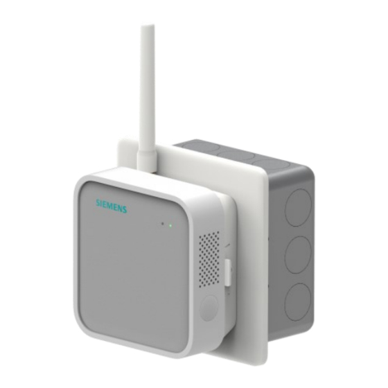
- Page 1 QNA2..D Indoor air quality multi-sensor Mounting A6V13562246_en--_a Smart Infrastructure 2022-11-15...
-
Page 2: Table Of Contents
Table of Contents Mounting and installation ........................3 Drywall mounting .............................5 Conduit box mounting ..........................7 Surface mounting .............................7 Connect multi-sensor to power source .....................9 Attach surface mount ..........................12 Power and secure multi-sensor ......................12 Notes ..............................14 Safety ..............................14 Disposal..............................14 Dimensions ............................15 2 | 16 A6V13562246_en--_a... -
Page 3: Mounting And Installation
Mounting and installation Drywall mounting 1 Mounting and installation For technical data, see Data sheet. For configuration, see Commissioning. Package Name Sensor module ● QNA2600D Surface mount ● BACnet: Surface mount ● LoRaWAN: Surface mount, antenna ● Set of screws and plastic insert In-wall mount ●... - Page 4 Mounting and installation Drywall mounting Select data mode ● With the inside (concave surface) facing you ensure that the mode selection switch points to 1 (LoRaWAN). For configuration of BACnet, see Commissioning. Preparing data connection Set up your LoRaWAN gateway router prior to installation and on-boarding if LoRaWAN is used ●...
-
Page 5: Drywall Mounting
Mounting and installation Drywall mounting Mounting location ● Devices should be mounted 3...6 feet from the floor (90 cm to 1.8 m high) and at least 16 feet (5 m) away from operable windows, air filters, and fresh air diffusers. ●... - Page 6 Mounting and installation Drywall mounting holes and trace along the inside edge of the 43 mm by 55 mm rectangular cut out. 2. Create an incision along the penciled line using your drywall cutting tool. The mount requires 2 inches of clearance behind the incision to install it.
-
Page 7: Conduit Box Mounting
Mounting and installation Conduit box mounting 1.2 Conduit box mounting 1. Locate the metal mounting plate provided in the In-wall mount kit. Line up the mounting plate with your conduit box and mount it in place using the provided conduit box screws. 2. - Page 8 Mounting and installation Surface mounting 3. Fold your two pairs of command strips in half so that the Velcro sides lock together and the sticker sides face outwards. Peel off the tape on one side of each command strip pair. 4.
-
Page 9: Connect Multi-Sensor To Power Source
Mounting and installation Connect multi-sensor to power source 5. Once you have a mounting location, peel the stickers off from the remaining two command strips attached to the back of your surface mount. 6. Use a level to straighten your surface mount and press firmly into the wall to secure the command strips in place. - Page 10 Mounting and installation Connect multi-sensor to power source Power over Ethernet (PoE) ● Run a cat 5e (or greater) Ethernet cable from your PoE switch, through the drywall incision, and into the Ethernet port (RJ45 connector) on the multi-sensor backpack. Low-voltage wiring ●...
- Page 11 Mounting and installation Connect multi-sensor to power source USB Type C wiring Without in-wall mount, USB Type C can be used to power the entire module. A6V13562246_en--_a 11 | 16...
-
Page 12: Attach Surface Mount
Mounting and installation Attach surface mount 1.5 Attach surface mount 1. Align the screw holes on your In-wall mount with the four cylindrical mounting plate pegs that extend out from the wall. Fit your In-wall mount over top so that the multi-sensor backpack disappears behind the wall and the back of the In-wall mount is flush with the mounting plate cover. - Page 13 Mounting and installation Power and secure multi-sensor Surface mounting 1. Attach the outlet power adapter to the end of the power cord and plug it into the nearest electrical outlet. 2. Click your multi-sensor into the surface mount and press the power button on the right side of the device to turn it on.
-
Page 14: Notes
Delete all personal data and dispose of the item(s) at separate collection and recycling facilities in accordance with local and national legislation. For additional details, refer to Siemens information on disposal. 14 | 16 A6V13562246_en--_a... -
Page 15: Dimensions
Dimensions 3 Dimensions Dimensions in mm A6V13562246_en--_a 15 | 16... - Page 16 Issued by Siemens Switzerland Ltd Smart Infrastructure Global Headquarters Theilerstrasse 1a CH-6300 Zug +41 58 724 2424 www.siemens.com/buildingtechnologies © Siemens Switzerland Ltd, 2022 Technical specifications and availability subject to change without notice. A6V13562246_en--_a...