Table of Contents
Advertisement
Quick Links
OPERATION AND MAINTENANCE INSTRUCTIONS
WITH ILLUSTRATED PARTS BREAKDOWN
MULTIBAND INTER/INTRA TEAM RADIO
INCLUDES SINCGARS, HAVEQUICK, ANDVT, RETRANSMISSION
(
CONFIGURATION NOTICE: This document contains technical information pertinent to the THALES PRC6991 MULTIBAND RADIO SET.
The information contained herein is for the support of the THALES PRC6991 MULTIBAND RADIO SET.
PROPRIETARY NOTICE: This document contains information proprietary to THALES COMMUNICATIONS, INC. It is furnished for
operation and support purposes only and not for reprocurement. All reprocurement and manufacturing rights are expressly reserved by THALES
COMMUNICATIONS, INC., and no such use may be made of this document, either directly or indirectly without the prior written consent of
THALES COMMUNICATIONS, INC.
ORGANIZATIONAL LEVEL
AN/PRC-148(V)(C)
THALES COMMUNICATIONS, INC.
22605 GATEWAY CENTER DRIVE
CLARKSBURG, MD 20871
COPYRIGHT : JUNE 1999
THALES COMMUNICATIONS, INC.
PUBLISHED AND CONFIDENTIAL WORK
ALL RIGHTS RESERVED
OCTOBER 9, 2002
)
Advertisement
Table of Contents

Related Manuals for Thales AN/PRC-148

Summary of Contents for Thales AN/PRC-148
- Page 1 PROPRIETARY NOTICE: This document contains information proprietary to THALES COMMUNICATIONS, INC. It is furnished for operation and support purposes only and not for reprocurement. All reprocurement and manufacturing rights are expressly reserved by THALES COMMUNICATIONS, INC., and no such use may be made of this document, either directly or indirectly without the prior written consent of THALES COMMUNICATIONS, INC.
-
Page 3: Table Of Contents
FRONT MATTER TABLE OF CONTENTS CHAPTER PAGE LIST OF FIGURES..............................IV LIST OF TABLES..............................VI SAFETY SUMMARY .............................VII FOREWORD ................................. VIII CHAPTER 1 GENERAL INFORMATION ....................1-1 MBITR D ..........................1-1 ESCRIPTION 1.1.1 Receiver-Transmitter Unit ......................... 1-1 1.1.2 Batteries ............................. 1-2 1.1.3 Holster and Accessory Carrying Bag.................... - Page 4 FRONT MATTER ANDVT O ..........................1-9 PERATION 1.7.1 Frequency Range ..........................1-10 1.7.2 Channel Bandwidth ......................... 1-10 1.7.3 Interoperability ..........................1-10 1.7.4 Operating Modes ..........................1-10 CHAPTER 2 OPERATING INSTRUCTIONS ....................2-1 ..................2-1 ONTROLS NDICATORS ONNECTORS 2.1.1 Controls ............................. 2-1 2.1.2 Indicators ............................
- Page 5 FRONT MATTER CHAPTER 5 ILLUSTRATED PARTS BREAKDOWN ................5-1 ..............................5-1 ENERAL ........................5-1 AINTENANCE ARTS ..........................5-2 UMERICAL NDEX (ESD) S ................ 5-3 LECTROSTATIC ISCHARGE ENSITIVE EVICES CAGE C ......................... 5-3 UMMARY CHAPTER 6 MBITR VEHICLE ADAPTER ....................6-1 ..............................
-
Page 6: List Of Figures
FRONT MATTER 9.1.10 Offset ............................9-1 9.1.11 Open Channel..........................9-2 9.1.12 Priority Scan..........................9-2 9.1.13 Repeater Delay..........................9-2 9.1.14 Scan Revert Channel........................9-2 9.1.15 Selected Channel........................... 9-2 9.1.16 Time of Day (TOD) ........................9-2 9.1.17 Transmit (TX) Timeout......................... 9-2 9.1.18 Word of Day (WOD) ........................ - Page 7 ...................... 3-7 IGURE ONTROL RYPTO LOCK IAGRAM 3-4 F ......................3-9 IGURE RONT ANEL LOCK IAGRAM 5-1 M (AN/PRC-148(V)(C))..........5-6 IGURE ULTIBAND NTER NTRA ADIO YSTEM 5-2 MBITR R (RTU) ..................5-9 IGURE ECEIVER RANSMITTER 6-1 RCH ................................ 6-3 IGURE 6-2 MBITR V ........................
- Page 8 ESULTS 4-2 O ....................4-2 ABLE PERATOR ROUBLESHOOTING UIDE 5-1 MBITR A ......................5-4 ABLE CCESSORY QUIPMENT 5-2 M , 20 (AN/PRC-148 (V)1(C))......5-7 ABLE ULTIBAND NTER NTRA ADIO YSTEM METER 5-3 M (AN/PRC-148 (V)2(C))....... 5-8 ABLE ULTIBAND NTER NTRA...
-
Page 9: Safety Summary
FRONT MATTER SAFETY SUMMARY The following are general safety precautions that are not related to any specific procedure, and do not appear elsewhere in this manual. These Safety Summaries are recommended precautions that all personnel must understand and apply during any given phase of operation and maintenance. -
Page 10: Foreword
FRONT MATTER FOREWORD NOTE: THIS MANUAL CONTAINS INFORMATION THAT IS CURRENT AS OF THE DATE SHOWN ON THE FRONT COVER. ADDITIONAL FUNCTIONALITY IS BEING DEVELOPED FOR THE RADIO AND THE APPEARANCE OF OPERATING SCREENS IS SUBJECT TO CHANGE FROM THOSE SHOWN HEREIN. The radio operation (man-machine interface) shown in this manual reflects radio software Revision U, Version 2.28 and PC Programmer Revion D, Version 1.03. -
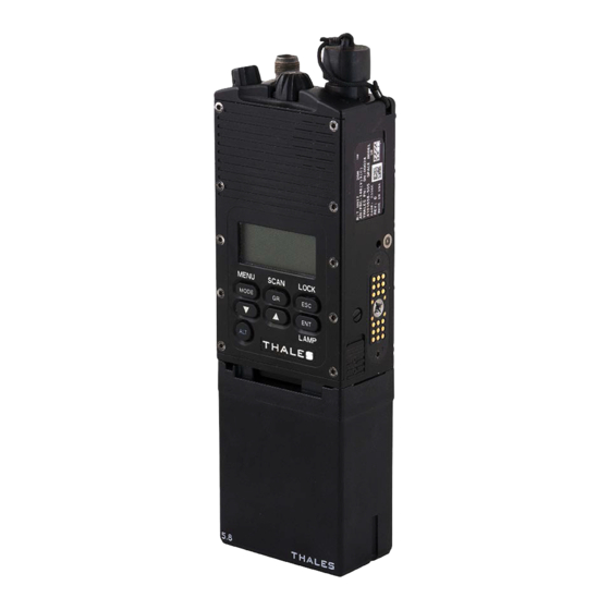
Page 12: Mbitr Unit
GENERAL INFORMATION Figure 1-1 MBITR Unit (Urban) with battery 1. Audio/Keyfill Connector (6-pin Urban version 15. Antenna/ shown) Antenna Connector 14. ON/OFF/Volume Control/Zeroize Switch 2. Channel Select Switch – 16 channels 13. Mechanical Interlock (not shown) 12. Programmable Function Keys 3. -
Page 13: Chapter 1 General Information
There are two versions: the Maritime version (AN/PRC-148 (V) 1(C)) is immersible in 20 meters of salt water for 2 hours, the Urban version (AN/PRC-148 (V) 2(C)) is immersible in 2 meters of salt water for 30 minutes. The MBITR operates in clear (analog) and secure (digital) voice and secure (digital) data. -
Page 14: Batteries
PRC6991ABS(BBS)-BAS, or basic, configuration includes one lithium-ion battery pack. 1.1.2.2 Battery Holder (Non-rechargeable) The MBITR (AN/PRC-148) standard equipment includes two each battery holders that allow the use of military standard or commercially available disposable, non-rechargeable lithium batteries (BA-5123/U or Duracell commercial model DL-123A or DL-2/3A). -
Page 15: Audio/Keyfill Adapter Device
GENERAL INFORMATION the connector from dirt and moisture when the antenna is not attached to the radio. The caps should be attached if the antennas may be immersed in water. 1.1.4.1 30-90 MHz Blade Antenna The 30-90 MHz blade antenna is capable of operating from 30 to 90 MHz with a minimum gain of -10 dBi. -
Page 16: Antennas
GENERAL INFORMATION 1.2.2 Antennas There are two high performance antennas available: a 116-174 MHz antenna (P/N SS-1600293-1) that provides improved performance (gain) in the upper VHF band and a 400-512 MHz antenna (P/N SS-1600294-1) that provides improved performance (gain) in the UHF band. 1.2.3 Vehicle Adapter The MBITR Vehicle Adapter (not currently available) is used to expand the capabilities of the... -
Page 17: Cables
GENERAL INFORMATION Assign programmable side key functions, • Operating frequencies (receive and transmit), • Squelch tones (receive and transmit), • Transmit power level, • Receive squelch threshold, • Encryption mode, • Transmit timeout, • Display backlight timeout, • Microphone HIGH/LOW gain, •... -
Page 18: Transceiver Characteristics
GENERAL INFORMATION Retransmission cable (P/N 3500485-501) that allows two radios to be connected together • to receive and retransmit voice or data traffic (retransmission mode). Transceiver Characteristics The radio is tunable over a frequency range of 30-512 MHz, in either 5 or 6.25 kHz tuning steps, using 25.0 kHz channel bandwidth, 12.5 kHz when set for narrowband operation, and 5 kHz bandwidth when set for ANDVT. -
Page 19: Compatibility
GENERAL INFORMATION 1.4.1 Compatibility When operating in the 16 kbps secure voice mode, the radio is VINSON compatible. When operating in the 12 kbps secure voice mode, the radio is FED-STD-1023 compatible. 1.4.2 Tone Squelch Disable When operating in the secure mode, the radio disables the transmission of any tone squelch (i.e., CTCSS) signals. -
Page 20: 1.4.10 Initial Synchronization
GENERAL INFORMATION 1.4.10 Initial Synchronization The MBITR has initial synchronization that is programmable at NONE, 256 msec, 384 msec, and 1.06 second. Initial synchronization controls the length of the cryptographic preamble to increase the probability of initial cryptographic synchronization by the receiving radio over noisy channels. SINCGARS Transmission Security (TRANSEC) NOTE: SINCGARS operation is only available in those radios with the optional SINCGARS capability enabled. -
Page 21: Havequick I/Ii Transmission Security
GENERAL INFORMATION HAVEQUICK I/II Transmission Security NOTE: HAVEQUICK operation is only available in those radios with the optional HAVEQUICK capability enabled. Use the “OPTIONS ENABLED” menu (paragraph 2.2.3.4.4) to check. The following describes the TRANSEC capabilities of the MBITR with HAVEQUICK option. 1.6.1 Frequency Range When operating in the HAVEQUICK I/II mode, the available MBITR operating frequency range... -
Page 22: Frequency Range
GENERAL INFORMATION 1.7.1 Frequency Range When operating in the ANDVT mode, the MBITR operating frequency range is contiguous from 30.0 to 512.0 MHz. 1.7.2 Channel Bandwidth The MBITR receiver/transmitter has a channel bandwidth of 5 kHz in ANDVT mode. 1.7.3 Interoperability The ANDVT MBITR is interoperable in mode and frequency with the Advanced Narrowband Digital Voice Terminal (ANDVT), KY-99, KY-99A, PSC-5, and AN/PRC-117F. -
Page 23: Chapter 2 Operating Instructions
OPERATING INSTRUCTIONS CHAPTER 2 OPERATING INSTRUCTIONS Section I. CONTROLS AND INDICATORS Controls, Indicators, and Connectors 2.1.1 Controls The MBITR controls consist of the following: a backlit keypad (shown in Figure 2-1), a push-to- talk (PTT) switch, ON/OFF/Volume control/Panic zeroize rotary switch, a 16-position channel select rotary switch, a squelch override button, and two programmable function keys. -
Page 24: Mbitr Controls And Connectors
OPERATING INSTRUCTIONS 2.1.1.2 Push-to-talk Switch A push-to-talk (PTT) switch (7, Figure 2-2) is located in the middle of the left side of the radio. (All positions are given as if the display is facing the radio operator.) By pressing the UP or DOWN arrow keys on the keypad while pressing the PTT switch, the user can change the output power level setting. -
Page 25: 2.1.2 Indicators
OPERATING INSTRUCTIONS Enable/Disable of Scan, Enable/Disable of backlighting, Enable/Disable of AM Swept Tone Beacon, Toggle through scan plans, Toggle through groups, Display/Clear SA positional information, Select between internal, external, and sidetone audio, Switch between Singel Channel and Frequency Hopping modes (SINCGARS and HAVEQUICK channels only), Display/Clear the clock and date. -
Page 26: Mbitr Controls And Connectors
OPERATING INSTRUCTIONS 4. AUDIO 7. ANTENNA CONNECTOR CONNECTOR 1. RF Connector 3. Battery Latch 2. Side Connector 6. ON/OFF/VOLUME/ZEROIZE 5. CHANNEL SELECT RADIO - TOP VIEW Figure 2-3 MBITR Controls and Connectors (Sheet 2) WIRING DIAGRAM FOR AUDIO/KEYFILL ADAPTER Figure 2-4 MBITR Audio/Keyfill Connector Pin-Out... -
Page 27: Operating Procedures
When the radio is first powered up, it performs a Power-On Self-Test (POST) and displays "TESTING". When POST is completed, the display shows “THALES MBITR” and the software version. NOTE: If the radio fails POST, run the Built-In Test (paragraph 2.2.3.4.1) to identify the cause of failure. -
Page 28: Figure 2-5 Default Display Screen
OPERATING INSTRUCTIONS a "SCAN" icon when the Scan function is active, • an "SA" indicator for Situation Awareness enabled (radio must be in CT mode), • a TRANSEC SINCGARS (SG) or HAVEQUICK (HQ) indicator with either a Single • Channel (SC) or Frequency Hopping (FH) indicator (NOTE: Since SINCGARS and HAVEQUICK are limited to FM and AM frequencies, respectively, the display DOES NOT include Modulation Type when TRANSEC channels are displayed, a “LNE”... -
Page 29: Sincgars Alternate Display (Sc)
OPERATING INSTRUCTIONS 2.2.2.3 Alternate DEFAULT Display (SINCGARS) For SINCGARS channels, there are different alternate displays for the Single Channel and Frequency Hopping modes. The Single Channel (SC) display includes the SINCGARS channel (1), Single Channel frequency (2), COMSEC key (3), data rate (4), modulation type (5), and frequency offset (6). -
Page 30: Andvt Alternate Display
OPERATING INSTRUCTIONS 1. Receive Frequency 2. Transmit Frequency RX = 245.85500 TX = 245.85500 3. Delay DELAY 135 MS 2.4K TEK 4 4. Operating Mode 5. Traffic Rate 6. COMSEC Key Figure 2-11 ANDVT Alternate Display 2.2.2.6 OPERATIONS Screens The Operations screens are required for basic operation of the MBITR. These include the Receive (RX) status, Transmit (TX) status/Power, and Squelch adjust screens. -
Page 31: Figure 2-15 Mode Select Screen
OPERATING INSTRUCTIONS operator with a small menu of options to select using the [t] and [u] keys. These selections must then be confirmed with an additional press of the [ENT] key. These Function changes are made with the MBITR online and immediately affect the way the MBITR is operating, e.g., Clear mode to Secure mode changes. -
Page 32: Programming Menu
OPERATING INSTRUCTIONS 2.2.2.7.3 GPS Transmit/Receive NOTE: The radio must be in CT mode to transmit or receive GPS information. TX SA Pressing [ENT] with GPS TX selected opens the GPS CID = 12345 transmit information screen. If a PLGR is attached, the LOCATION GPS TX screen will display the Combat ID (CID) and current location (using the Military Grid Reference... -
Page 33: Clear All Screen
OPERATING INSTRUCTIONS 2.2.3.1.2 CLEAR ALL Screen The CLEAR ALL screen (Figure 2-21) will zeroize all the ALL KEYS AND DFLTS COMSEC and TRANSEC key variables and will reset the WILL BE ZEROIZED radio to the factory defaults (Table 2-2). Press [ESC] to ARE YOU SURE? return to the Initial ZEROIZE Screen. -
Page 34: Transec Zeroize Screen
OPERATING INSTRUCTIONS 2.2.3.1.4 TRANSEC Zeroize Screen Move the selection outline to TRANSEC and press [ENT] to HOP AND LOCK SETS WILL BE ZEROIZED proceed with TRANSEC zeroize (See Figure 2-25). Press ARE YOU SURE? [ENT] to immediately zeroize ALL TRANSEC hopsets and Y = ENT N = ESC lockout sets (SINCGARS) and Word of Day data... -
Page 35: Comsec Keyfill
OPERATING INSTRUCTIONS TOD: Enables the HAVEQUICK I/II Time of Day load functions (load, transmit, emergency initialize). MWOD-A: Enables the HAVEQUICK I/II Multiple Word of Day load from an external fill device (e.g., KYK-13.) MWOD-M: Enables a manual load of the HAVEQUICK I/II data from the keypad and display. 2.2.3.2.2 COMSEC Key Fill Operation NOTE: If the crypto alarm sounds when "COMSEC KEYFILL... -
Page 36: Transec Fill Screen
OPERATING INSTRUCTIONS 2.2.3.2.2.3 Scenario 3-Alarm Screen If the key is recognized as an invalid key, the radio will register an alarm (see Default Display, Figure 2-5). The operator must press the PTT to clear the alarm. When the alarm is cleared by pressing PTT, the process restarts with the COMSEC key fill screen. If the operator continually (more than three times in a row) experiences Scenario 2-Alarm, then either the key fill device is bad, the MBITR is bad, the key fill device has a bad key or no key, or the key fill device is turned off. -
Page 37: Tod Selection Screen
OPERATING INSTRUCTIONS 2.2.3.2.5 HAVEQUICK I/II TOD Fill Time of Day (TOD) Fill is used to load a HAVEQUICK PLGR TOD time of day, transmit a time of day, or perform an RX TOD Emergency Initialization. To load, first ensure the radio is set to a HAVEQUICK SC channel. -
Page 38: Mwod-M Screen
OPERATING INSTRUCTIONS successful, the MWOD value on the screen will increment by one. Continue pressing the PTT until all the MWOD sets are loaded. 2.2.3.2.7 HAVEQUICK I/II MWOD-M Fill The MWOD-M (Multiple Word Of Day - Manual) screen OPR DAY = OK allows the user to load HAVEQUICK I/II data through WOD = ** the keypad and display. -
Page 39: Fmt Fill Screen
OPERATING INSTRUCTIONS Scrolling up from the P20 line reverts to the MWOD MWOD 1 (3) screen (Figure 2-39); scrolling down from the P18 line DAY = 00 opens the second MWOD FILL screen (for P17 through P15). Scrolling down from P15 on the second screen opens the MWOD Day of the Month screen (Figure 2-41). -
Page 40: Figure 2-43 Lockout Set Erf
OPERATING INSTRUCTIONS b. On the DTD: 1. Turn on and select the "Fill" application. Use the 'Utility" function, if necessary, to select the K15 (KYX-15 emulation) protocol. 2. Press "N" to select the "Net" function. 3. Press "A" to select the "SARK-AK" function. 4. -
Page 41: Figure 2-45 Initial Programming Screen
OPERATING INSTRUCTIONS 2.2.3.3 Programming A typical programming screen or menu may contain one GLOBAL or more Sub Menu selections or Field / Item selections. The main menu screen is shown in Figure 2-19. Select RADIO CONFIG PROGRAM and press [ENT] to open the initial EMERGENCY programming screen, illustrated in Figure 2-45. -
Page 42: Figure 2-48 Transmit Timeout Screen
OPERATING INSTRUCTIONS 30 SEC 10 SEC 60 SEC 20 SEC 90 SEC 30 SEC 120 SEC 40 SEC Figure 2-48 Transmit Timeout Screen Figure 2-49 Backlight Timeout Screen SIDE ENABLE DAY : 0 HOURS : 00 MIC LVL LOW MINUTES : 00 Figure 2-50 Set Clock Screen Figure 2-51 Side Connector Enable 2.2.3.3.2 RADIO CONFIG... - Page 43 OPERATING INSTRUCTIONS up the screen to previous selection or to return to this screen from the following screen, use the [t] key. On the following screens, only the programmable parameters available for the selected operating mode are displayed; other parameters are blanked out. 2.2.3.3.3 Basic Channel Programming Options The Basic Channel Programming screens (two screens) allow the user to set channel-specific parameters from the front keypad and display.
- Page 44 OPERATING INSTRUCTIONS want to change a selection, press the [u] to move to the next line (or the next screen) or [t] to move to the previous line (or previous screen). 1. RX FREQUENCY 2. TX FREQUENCY RX = 167.56250 8.
- Page 45 OPERATING INSTRUCTIONS 2.2.3.3.4 SINCGARS Channel Programming Options The SINCGARS Channel Programming screens (two screens) allow the user to set channel- specific parameters from the keypad and display. Individual channels can be programmed for: Table 2-5 Channel Options (SINCGARS) Parameter Value SINCGARS SINCGARS Channel: 1-6, MAN, CUE ECCM...
- Page 46 OPERATING INSTRUCTIONS 2.2.3.3.5 HAVEQUICK Channel Programming Options The HAVEQUICK Channel Programming screens (two screens) allow the user to set channel- specific parameters from the front keypad and display. If ECCM = SC, the first line will show FX = ; if ECCM = FH, the first line will show NET =. Individual channels can be programmed for: Table 2-6 Channel Options (HAVEQUICK) Parameter...
- Page 47 OPERATING INSTRUCTIONS outline to the ECCM mode. The remaining parameters are changed similarly. Note that Modulation Type (AM) and Traffic rate (16K) cannot be changed. To use the HAVEQUICK Training Nets, NET must be set to A00.000 – A00.400 for HAVEQUICK I or A00.025 –...
-
Page 48: Figure 2-57 Group Programming Screen
OPERATING INSTRUCTIONS Channel. Other parameters are programmed similarly. Delay is the time between the transmit carrier going active without modulation and the carrier having modulation applied. A training frame is a 32-bit pattern of alternating “0s” and “1s”. Training frames are used to improve the chances of initial signal acquisition by providing a repetitive pattern for synchronization and mode identification. -
Page 49: Figure 2-59 Emergency Programming Screen
OPERATING INSTRUCTIONS 2.2.3.3.8 Emergency Programming Options The Emergency Programming screen (Figure 2-59) is accessed from the main function menu (Figure 2-19). This screen allows the user to select either the user-programmable emergency beacon channel (Figure 2-60) or situation awareness (Figure 2-58) programming. The user- programmable parameters for the emergency beacon channel are: transmit frequency and transmit on/off times. -
Page 50: Scan
OPERATING INSTRUCTIONS 2.2.3.4.3 Elapsed Time TX = XXXX:XX The Elapsed Time Screen shows the total time the RX = XXXX:XX radio has been in Transmit mode (PTT pressed), Receive mode (actively receiving radio signals with STBY = XXXX:XX audio output), and Standby mode (powered on but neither transmitting nor receiving). -
Page 51: Figure 2-67 Active Scan Screen
OPERATING INSTRUCTIONS 2.2.4.2 Scan Operation Open the initial SCAN operation screen (Figure 2-66) by pressing [ALT] and [GR] from the default display SCAN (Figure 2-5). The display has four choices: SCAN (enable), PRI (Priority selection), SPLAN (select a scan SPLAN plan), and CONFIG (program a scan plan). -
Page 52: Figure 2-69 Select Scan Plan
OPERATING INSTRUCTIONS 2.2.4.2.3 Select SCAN Plan (SPLAN) 3-Character alphanumeric label The Select Scan Plan screen (Figure 2-69) opens with the selected Scan Plan highlighted in reverse video. To select a different Scan Plan, use the [t] or [u] keys to move the selection outline. -
Page 53: 2.2.5 Cloning Operation
OPERATING INSTRUCTIONS 2.2.5 Cloning Operation NOTE COMSEC/TRANSEC keys cannot be transferred via the cloning mode. HAVEQUICK Operational day, WOD, MWOD, and FMT are transferred. NOTE Ensure that both radios are set for INTERNAL AUDIO and SIDE CONNECTOR ENABLED. The cloning function enables one radio to transfer its programmed data into another radio. To clone programmed information from one radio to another, connect the SEND end of the cloning cable (3500395-501) to the side connector of the Sending radio (the radio set with the information to be cloned) and the RECEIVE end of the cloning cable to the side connector of the... -
Page 54: Digital Data Operation
OPERATING INSTRUCTIONS If cloning is unsuccessful, or if the connection with the receiving radio is not made within the timeout period, the SEND radio will display the following error message: CLONING SENDING ERROR 2.2.6 Digital Data Operation NOTE Ensure the channel is set for encrypted mode (CT) and that the SIDE CONNECTOR ENABLED. -
Page 55: Expedient Retransmission
OPERATING INSTRUCTIONS The digital data cable (3500396-501), which connects to a standard 25-pin serial connector, can provide similar capability with selected data terminal software. However, the primary use is in testing radio Bit Error Rate (BER) in data operation. 2.2.7 Expedient Retransmission The MBITR has the capability for “expedient retransmission”... -
Page 57: Chapter 3 Principles Of Operation
PRINCIPLES OF OPERATION CHAPTER 3 PRINCIPLES OF OPERATION Section I. FUNCTIONAL SYSTEM(S) OPERATION General This section describes the theory of operation of the radio set. From both technical and operational standpoints, the radio set is designed to be a component of a communications system. A radio set must function in conjunction with other similar AM and FM radios to perform its purpose: two- way communication. -
Page 58: Transceiver Module
PRINCIPLES OF OPERATION 3.2.1 Transceiver Module The transceiver module, which mates with the radio set chassis to complete the MBITR assembly, covers the entire 30-512 MHz frequency range. The transceiver module is made up of two circuit card assemblies: the Transmit Assembly and the Synthesizer Assembly. The transceiver provides frequency and changeover control for either transmitting or receiving a signal, as well as the modulator and power amplifier for the MBITR. -
Page 59: Rechargeable Lithium Ion Battery
PRINCIPLES OF OPERATION 3.2.3.2 Chassis Assembly The MBITR chassis assembly includes the chassis casting, the side connector flexi cable, the battery flexi cable, the mode switch, channel select switch, and power/volume switch flexi cable, the power/volume switch, the audio accessory connector, the antenna connector, and the channel select switch. -
Page 60: 3.3.1 Receiver/Synthesizer Cca
PRINCIPLES OF OPERATION 3.3.1 Receiver/Synthesizer CCA The following functions are located on the Receiver/Synthesizer Board: • Reference Oscillator • Synthesizer/VCOs • Local Oscillators • IF Chain • EEPROM Calibration Data. 3.3.2 Transmit CCA The following functions are located on the Transmit Board: •... -
Page 61: Figure 3-2 Transceiver Module Block Diagram
PRINCIPLES OF OPERATION Control Control Voltage Voltage Feedback Bipolar Second TX OUT Mixer Toko To TX CCA Variable Variable 1227 MHz Toko 86.85 MHz +12dB +11.5dB 1227 MHz Att. Att. Diplexer RF2304 SAW BPF 1254.8 to 1750.7 RF2812 +18 dB Micro Control to 1140 Modulator... -
Page 62: Control/Crypto Circuit Card Assembly (Cca)
PRINCIPLES OF OPERATION Control/Crypto Circuit Card Assembly (CCA) Refer to Figure 3-3 for the block diagram for the control/crypto CCA. As shown, the control/crypto CCA consists of the following functional elements: 3.4.1 Microcontroller Mode Selection • Key Selection • Algorithm Selection •... -
Page 63: Figure 3-3 Control/Crypto Block Diagram
PRINCIPLES OF OPERATION TOP CONNECTOR 10-PIN ONLY TOP CONNECTOR RECEIVE PATH EXTAUDIO+ SIDE CONNECTOR SERCTRLDATAIN/SERCTRLDATAOUT EXTAUDIO- H8D[15..8] SERBDR0 DECODER FPGA 450 kHz IF SERDACDATA REDD[15..8] BLACK INTERNAL SPEAKER PTOUT CTIN 232RXD CRYPTOGRAPHIC SERAVRDT1 MODULE SIDE CONNECTOR CONTROLO/CRYPTO BOARD 232CLK TO FPGA /DDMC TRANSMIT PATH TOP CONN MIC... -
Page 64: Fpga
PRINCIPLES OF OPERATION 3.4.5 FPGA CODEC Control Interface • Clock Division • PTT Switch Interface • Clear/Secure Bypass Logic • Bus Arbitrator • Microcontroller I/O Expansion • RED DSP interface • BLACK DSP interface • Serial to Parallel and Parallel to Serial Conversion. •... -
Page 65: Figure 3-4 Front Panel Block Diagram
PRINCIPLES OF OPERATION INDICTOR LCD DISPLAY POWER KEYRET SUPPLY ON/OFF/VOLUME - 3 WIRES CHANNEL SWITCH - 4 WIRES KEY FILL MICROCONTROLLER FRONT PANEL - SCI0 KEYPAD & OPTION1/2- 9 WIRES INDICTOR KEY FILL SELECT SELECT INPUT LEVEL INDICTOR AUDIO/KEY FILL I/O COMSEC KEY FILL PORT MULTIPLEXER CONVERTER... -
Page 66: Chassis Assembly
PRINCIPLES OF OPERATION The input from the internal microphone or the side connector goes directly to a CODEC on the Front Panel, which consists of microphone preamplifiers for the three audio inputs (internal, audio connector, and side connector microphone), an Analog to Digital Converter, and a Digital to Analog Converter. -
Page 67: Chapter 4 Maintenance
MAINTENANCE CHAPTER 4 MAINTENANCE General. This chapter provides operator maintenance instructions for the MBITR radio. This includes operational checkout, inspection preventive maintenance, troubleshooting, removal/replacement procedures. Operational Checkout. The radio has a Power-On-Self-Test (POST) function that checks basic radio functions every time the radio is powered up. -
Page 68: Troubleshooting
MAINTENANCE storage) be periodically charged to full capacity. The recommended interval for periodic charging is twelve (12) weeks. If the battery has been charged while attached to a “powered-on” radio, the radio may exhibit a problem communicating with the rechargeable lithium-ion battery. The “fuel gauge” display for a fully charged battery may show only a partially full or empty battery. - Page 69 MAINTENANCE Symptom Probable Cause Corrective Action Limited talk range • Obstacles (buildings, heavy • Move away from the foliage) are obstructing the obstructions; increase the height signal of the radio, if possible. • Battery power is low • Check battery “fuel gauge”; •...
-
Page 70: Removal/Replacement Procedures - Operator
MAINTENANCE Symptom Probable Cause Corrective Action Radio does not • Side connector disabled • Enable side connector (Global recognize that cloning programming, paragraph cable (or other cables, 2.2.3.3.1) such as Retrans) is connected Radio does not respond • Radio set for external audio •... -
Page 71: Audio Accessory Removal/Replacement (Maritime Version)
MAINTENANCE 4.6.2 Audio Accessory Removal/Replacement (Maritime version). Remove/replace the audio accessory as follows: a. Disconnect the audio accessory (e.g., handset), from the audio accessory connector on the top of the receiver-transmitter by unscrewing the knurled ring on the connector plug counter-clockwise until it is loose and pulling the cable connector straight up from the radio. -
Page 72: Watertight Integrity
MAINTENANCE battery (e.g., by operating the radio until the radio shuts down) and then placing the discharged battery in the charger to complete a charge cycle (LED turns green). Watertight Integrity The receiver-transmitter is not authorized for disassembly. However, in the event of a combat situation where it becomes necessary for partial disassembly of the RTU, the watertight seals will be compromised. -
Page 73: Chapter 5 Illustrated Parts Breakdown
MBITR Maritime (AN/PRC-148(V)1(C)) and Urban (AN/PRC-148(V)2(C)) versions, manufactured by Thales Communications, Inc., Clarksburg, Maryland. Table 5-1 lists available items of equipment that are not supplied as part of the basic AN/PRC-148 system. Maintenance Parts List. The Maintenance Parts List (MPL), (Section II), consists of the complete systems divided into main groups. -
Page 74: Numerical Index
ILLUSTRATED PARTS BREAKDOWN indented and marked with a "i" are part of the first unindented part above it. Additional information following the item description may include the following: a list of alternate part numbers to give stock ordering information; exceptions to the Usable On Code for the item; and references to preceding and subsequent figures concerning assemblies and subassemblies. -
Page 75: Electrostatic Discharge (Esd) Sensitive Devices
The MPL contained within this manual with ESD sensitive parts are identified by the following symbol (ESD). These symbols are placed in the extreme right of the description column for the item identified as ESD sensitive. CAGE Code Summary. CAGE Code Manufacturer 23386 Thales Communications, Inc. - Page 76 ILLUSTRATED PARTS BREAKDOWN Table 5-1 MBITR Accessory Equipment (not included with the basic radio system) Description Part Number Application Single Unit Battery Charger 1600426-1 Charges one lithium-ion battery at a time; uses AC input power only. Six Unit Battery Charger 1600426-2 Charges six lithium-ion batteries simultaneously;...
- Page 77 ILLUSTRATED PARTS BREAKDOWN Description Part Number Application Speaker Microphone 1600469-4 Handheld speaker microphone with volume control; 6-pin audio connector Maritime Headset 1600503-5 20 meter immersible headset with 10-pin audio connector Urban Headset 1600567-1 (Alt. 2 meter immersible headset with 6-pin audio 1600504-1) connector Commercial Lightweight...
-
Page 78: Figure 5-1 Multiband Inter/Intra Team Radio System (An/Prc-148(V)(C))
ILLUSTRATED PARTS BREAKDOWN 1. MBITR 3. Antenna 9. Extra Li-Ion Battery 2. Li-Ion Battery 4. Antenna 8. Audio/Key Fill Adapter 7. Non-Rechargeable Battery Box 6. Holster 5. Accessory Figure 5-1 Multiband Inter/Intra Team Radio System (AN/PRC-148(V)(C)) -
Page 79: Table 5-2 Multiband Inter/Intra Team Radio System, 20 Meter (An/Prc-148 (V)1(C))
PAOZZ Operator Manual NOTE: The above parts list applies to the AN/PRC-148(V)1(C) system (Thales part number PRC6991ABS-SYS). Thales also has a similar system (part number PRC6991ABS-BAS) that includes one (1) rechargeable battery (p/n 1600515-X) and does not include any battery holders (p/n 4101240-501). -
Page 80: Table 5-3 Multiband Inter/Intra Team Radio System, 2 Meter (An/Prc-148 (V)2(C))
PAOZZ Operator Manual NOTE: The above parts list applies to the AN/PRC-148(V)2(C) system (Thales part number PRC6991BBS-SYS). Thales also has a similar system (part number PRC6991BBS-BAS) that includes one (1) rechargeable battery (p/n 1600515-1) and does not include any battery holders (p/n 4101240-501). - Page 81 ILLUSTRATED PARTS BREAKDOWN Figure 5-2 MBITR Receiver-Transmitter Unit (RTU) NOTE Figure 5-2 shows the component parts of both the Maritime and Urban versions of the MBITR. The actual part numbers of these two versions are listed in Tables 5-4 and 5-5, respectively.
- Page 82 ILLUSTRATED PARTS BREAKDOWN Table 5-4 MBITR Unit, 20 Meter (4101104-501) Figure & Index Description Units per Part Number CAGE 1 2 3 4 5 6 7 Assy SMR Code 5-2-1 70211 23386 Splice - Open Barrel PAOZZ 5-2-2 3600188-1 23386 Cap, Dust, Connector PAOZZ 5-2-3 4101141-501...
- Page 83 ILLUSTRATED PARTS BREAKDOWN Table 5-5 MBITR Unit, 2 Meter (4101195-501) Figure & Index Description Units per Part Number CAGE 1 2 3 4 5 6 7 Assy SMR Code 5-2-1 70211 23386 Splice - Open Barrel PAOZZ 5-2-2 3600188-1 23386 Cap, Dust, Connector PAOZZ 5-2-3 4101194-501...
-
Page 85: Chapter 6 Mbitr Vehicle Adapter
VEHICLE ADAPTER CHAPTER 6 MBITR VEHICLE ADAPTER General The MBITR Vehicle Adapter (MA6943) allows the MBITR to be readily mounted in a variety of vehicles. The Vehicle Adapter : Has a 12-32 VDC power supply for operation with most vehicle electrical systems, •... -
Page 86: Weight
For RF output settings of 3 or 5 watts, power is supplied by the MBITR charged battery. The VA includes a battery charging system that can recharge the MBITR rechargeable lithium- ion battery (Thales p/n 1600515-X) within four hours. NOTE: The VA will only recharge the Li-ion battery at temperatures between 0° and 45° C. -
Page 87: Maintenance
VEHICLE ADAPTER • Volume Knob – replaced by a rocker key marked (+) and (-), alternate function is external speaker off or on; • Channel Knob – replaced by a rocker key marked with ( ) and ( ); programming function is UP and DOWN arrow, alternate function is LEFT and RIGHT arrow;... -
Page 89: Chapter 7 Special Power Adapter Interface (Spai)
SPECIAL POWER ADAPTER INTERFACE CHAPTER 7 SPECIAL POWER ADAPTER INTERFACE (SPAI) General The MBITR Special Power Adapter Interface (SPAI) is used with the power sources found in the Special Operations Power Supply (SOPS) assembly, the SOPS OP 177(V)1/U. The SOPS assembly provides power for field recharging of nickel-cadmium and lead acid batteries used to power military communications/electronic equipment assigned to Army SOF units. -
Page 90: Operation
SPECIAL POWER ADAPTER INTERFACE • Short circuit to ground or a short circuit in either the battery or Receiver/Transmitter • Excessive temperatures, if natural cooling is prevented • Over-voltage input of the supply voltage Operation See Figure 7-1. NOTE: The radio should be OFF until all connections to the SPAI and power source are made. -
Page 91: Performance
SPECIAL POWER ADAPTER INTERFACE Performance The SPAI will charge a fully discharged MBITR lithium ion battery within 3.0 hours at a nominal battery temperature (+21 C). The battery is charged to within 90% of capacity in the first two hours. The SPAI is capable of charging over a temperature range -10°C to +40°C. However, the charge time will vary depending on the response of the lithium ion chemistry. -
Page 93: Chapter 8 Battery Chargers
There are three different versions of MBITR battery chargers: single unit, AC power only; six unit AC power only; and six unit AC/DC power. The MBITR battery chargers are also capable of recharging the batteries used on other Thales radios: the Racal 25, MSHR, and 20 meter MSHR. -
Page 94: Six (6) Unit Chargers
BATTERY CHARGERS 8.3.2 Six (6) Unit Chargers. There are two versions of the six-unit charger (Figure 8-2) available. Both versions of the charger are able to operate from universal power sources defined as 90 to 265 VAC, 50-400 Hz. One model of the charger can also operate from 10 to 32 VDC as well. The charger requires no modification or adjustment in order to operate from any voltage within this range. - Page 95 BATTERY CHARGERS CAUTION Do not insert a new battery in the charger until the LED is turned off. The battery can be charged while attached to a radio. However, the radio MUST be powered OFF. (See paragraph 4.4 for additional information.)
-
Page 96: Illustrations
BATTERY CHARGERS Illustrations Figure 8-1 MBITR Single Charger Figure 8-2 MBITR Multi-Charger... -
Page 97: Chapter 9 Definitions
DEFINITIONS CHAPTER 9 DEFINITIONS Definitions 9.1.1 Active Channel The Selected Channel is receiving a signal that is of sufficient strength to overcome the programmed squelch level. 9.1.2 Channel (100 per radio) a memory location with defined: receive, transmit, squelch, modulation, and power settings. -
Page 98: 9.1.11 Open Channel
DEFINITIONS 9.1.11 Open Channel The squelch level is overridden and the radio is in a constant receive state. 9.1.12 Priority Scan The priority channel(s) are sampled preferentially during scanning. 9.1.13 Repeater Delay When operating with a signal repeater, the radio can be programmed to disable reception for a brief delay after the PTT is released at the end of a transmission. -
Page 99: Index
INDEX INDEX Emergency Programming ........2-27 Expedient Retransmission......... 2-33 Accessories............1-3 Battery Chargers..........1-4 Cables............... 1-5 Functional Operation .......... 3-1 List ..............5-4 Battery Holder..........3-3 PC Programmer..........1-4 Control/Crypto CCA ........3-2 Special Power Adapter Interface....1-4 Lithium Ion Battery........3-3 Vehicle Adapter.......... - Page 100 INDEX Radio Maintenance ..........2-27 SINCGARS TRANSEC ........1-7 Radio Maintenance Special Power Adapter Interface ......7-1 Check Clock............ 2-27 Radio Maintenance Options............2-28 TRANSEC Zeroize..........2-12 Radio Parameters Zeroize........2-12 Receiver-Transmitter Unit........1-1 Vehicle Adapter ........... 6-1 Scan ..............2-28 Active SCAN ..........
- Page 102 SOFC4I-00-G10-00253-00 Thales Part 84329 Rev. E Thales Communications, Inc. 22605 Gateway Center Drive Clarksburg, MD 20871 1-800-914-0303 E-mail: Customer.Service@thalescomminc.com...
Need help?
Do you have a question about the AN/PRC-148 and is the answer not in the manual?
Questions and answers