
Related Manuals for Nortel 4524GT


Summary of Contents for Nortel 4524GT
-
Page 1: Installation Guide
Nortel Ethernet Routing Switch 4500 Series Installation Guide NN47205-300 (322811-B) -
Page 2: Canadian Department Of Communications Radio Interference Regulations
In the interest of improving internal design, operational function, and/or reliability, Nortel Networks reserves the right to make changes to the products described in this document without notice. Nortel Networks does not assume any liability that may occur due to the use or application of the product(s) or circuit layout(s) described herein. -
Page 3: En 55022 Statement
Règlement sur le brouillage radioélectrique du ministère des Communications Cet appareil numérique (Nortel Ethernet Routing Switch 4500 Series) respecte les limites de bruits radioélectriques visant les appareils numériques de classe A prescrites dans le Règlement sur le brouillage radioélectrique du ministère des Communications du Canada. -
Page 4: Mic Notice (Republic Of Korea Only)
National Safety Statements of Compliance EN 60950 statement This is to certify that the Ethernet Routing Switch 4500 Series equipment is in compliance with the requirements of EN 60950 in accordance with the Low Voltage Directive. Additional national differences for all European Union countries have been evaluated for compliance. -
Page 5: Información Nom (Unicamente Para México)
Norma Oficial Méxicana (NOM): Exportador: Nortel Networks, Inc. 4655 Great America Parkway Santa Clara, CA 95054 USA Importador: Nortel Networks de México, S.A. de C.V. Avenida Insurgentes Sur #1605 Piso 30, Oficina Col. San Jose Insurgentes Deleg-Benito Juarez México D.F. 03900... -
Page 6: National Environmental Statements Of Compliance
Specifically, restricted materials under the RoHS Directive are Lead (including solder used in PCB’s), Cadmium, Mercury, Hexavalent Chromium, and Bromine. Nortel declares compliance with the European Union (EU) RoHS Directive (2002/95/EC). WEEE Directive Compliance Statement This product at end of life is subject to separate collection and treatment in the EU Member States, Norway, and Switzerland and therefore is marked with the symbol shown at the left. -
Page 7: Table Of Contents
Environmental requirements 19 Package contents 20 Installing the Nortel Ethernet Routing Switch 4500 Series on a table or shelf 21 Installing the Nortel Ethernet Routing Switch 4500 Series in an equipment rack 23 Cabling requirements for the Nortel Ethernet Routing Switch 4500 Series 25... - Page 8 Nortel DC to DC converter module 38 Connecting AC power 38 Power cord specifications 38 Connecting power to the back panel 39 Checking Light Emitting Diode (LED) on the Nortel Ethernet Routing Switch 4500 Series 40 Front panel LEDs 40 Switch LED state indicators 44...
-
Page 9: New In This Release
New in this release The following sections detail what’s new in Nortel Ethernet Routing Switch 4500 Series - Installation Guide (NN47205-300) for release 5.1. • "Features" (page 9) • "Other changes" (page 9) Features For information about changes that are feature-related, see the following sections: •... - Page 10 10 New in this release Nortel Ethernet Routing Switch 4500 Series Installation Guide NN47205-300 (322811-B) 03.01 Standard 5.1 19 November 2007 Copyright © 2007, Nortel Networks...
-
Page 11: Preface
Preface This guide provides information and instructions to install a 4500 Series Nortel Ethernet Routing Switch. For information about configuration and management of the switch, see the documentation included with the switch and the product release notes. In addition, before you start the installation... -
Page 12: Related Publications
Nortel Ethernet Routing Switch 4548GT–PWR Related publications For more information about managing, configuring, and using the Nortel Ethernet Routing Switch 4500 Series switches, see the publications listed Table 2 "Nortel Ethernet Routing Switch 4500 Series Documentation and related information" (page NN47205-300 (322811-B) 03.01 Standard... - Page 13 Table 2 Nortel Ethernet Routing Switch 4500 Series Documentation and related information Title Nortel Ethernet Routing Switch 4500 Series Regulatory Information Nortel Ethernet Routing Switch 4500 Series Installation Nortel Ethernet Routing Switch 4500 Series Release Notes - Software Release 5.0...
-
Page 14: Finding The Latest Updates On The Nortel Web Site
Getting help over the phone from a Nortel Solutions Center If you do not find the information you require on the Nortel Technical Support web site, and have a Nortel support contract, you can also get help over the phone from a Nortel Solutions Center. -
Page 15: Getting Help From A Specialist By Using An Express Routing Code
ERC for your product or service, go to: www.nortel.com/erc Getting help through a Nortel distributor or reseller If you purchased a service contract for your Nortel product from a distributor or authorized reseller, contact the technical support staff for that distributor or reseller. - Page 16 16 Preface Nortel Ethernet Routing Switch 4500 Series Installation Guide NN47205-300 (322811-B) 03.01 Standard 5.1 19 November 2007 Copyright © 2007, Nortel Networks...
-
Page 17: Installing The Nortel Ethernet Routing Switch
Installing the Nortel Ethernet Routing Switch This section provides the information and procedures to install the Nortel Ethernet Routing Switch 4500 Series. Unless otherwise noted, tasks in this section apply to all switches in this series. This section contains the following topics: •... -
Page 18: Electrostatic Discharge
Preventing electrostatic damage in new cable installations With new cable installations, Nortel recommends that you use an ESD discharge cable to reduce the potential for damage from static, that can build up in cables. The following figure illustrates an ESD cable. -
Page 19: Environmental Requirements
Environmental requirements Table 3 "Nortel Ethernet Routing Switch 4500 Series environmental requirements" (page 19) individual switches in this series. Ensure that the area where you install the switch and where it will operate meets these requirements. -
Page 20: Package Contents
Miscellaneous Operating Considerations Package contents "Nortel Ethernet Routing Switch 4500 Series package contents" (page illustrates the components that are provided with each switch in the 4500 Series. If any components are missing, contact the switch vendor. NN47205-300 (322811-B) 03.01 Standard Copyright ©... -
Page 21: Installing The Nortel Ethernet Routing Switch 4500 Series On A Table Or Shelf
Installing the Nortel Ethernet Routing Switch 4500 Series on a table or shelf 21 Nortel Ethernet Routing Switch 4500 Series package contents 1. Nortel Ethernet Routing Switch 4500 Series 2. Rack-mounting hardware that includes • Rack-mount brackets • Screws to attach brackets to the switch •... - Page 22 22 Installing the Nortel Ethernet Routing Switch To install a 4500 Series switch on a table or shelf, perform the following procedure. Step Action Attach the included rubber footpads on the bottom of the switch at the locations indicated in...
-
Page 23: Installing The Nortel Ethernet Routing Switch 4500 Series In An Equipment Rack
Installing the Nortel Ethernet Routing Switch 4500 Series in an equipment rack 23 Nortel Ethernet Routing Switch on a desk or shelf Installing the Nortel Ethernet Routing Switch 4500 Series in an equipment rack Before you start this procedure, ensure that the equipment rack meets these requirements: •... - Page 24 24 Installing the Nortel Ethernet Routing Switch Step Action Attach a bracket to each side of the switch using a #2 Phillips screwdriver as illustrated in Attaching switch brackets Slide the switch into the rack as illustrated in (page Mounting the switch Insert and tighten the rack-mount screws using a #2 Phillips screwdriver.
-
Page 25: Cabling Requirements For The Nortel Ethernet Routing Switch 4500 Series
Installation and removal of Small Form-factor Pluggable (SFP) transceivers The following section describes how to install and remove SFP transceivers in the Nortel Ethernet Routing Switch 4500 Series. For complete information about SFP transceiver use and designation, see Installing SFP and XFP Transceivers and GBICs (318034-D) NN47205-300 (322811-B) 03.01 Standard... -
Page 26: Installation Of Sfp Transceivers
26 Installing the Nortel Ethernet Routing Switch Installation of SFP transceivers This section describes how to install SFP transceivers. To install SFP transceivers, perform the following procedure. Step Action Remove the transceiver from the protective packaging. Verify that the transceiver is the correct model for the network configuration. -
Page 27: Removal Of Sfp Transceivers
Discard transceivers in accordance with the proper laws and regulations. NN47205-300 (322811-B) 03.01 Standard Copyright © 2007, Nortel Networks "Transceiver locking/extractor mechanism examples" 27). ATTENTION Nortel Ethernet Routing Switch 4500 Series Installation Guide 5.1 19 November 2007... -
Page 28: Rj-45 Connector Pin Assignments
RJ-45 connector pin assignments The following section describes the connector pin assignments for the RJ-45 connectors in the Nortel Ethernet Routing Switch 4500 Series switches. See the appropriate section for specific information on an individual switch: Table 5 "4548GT and 4548GT PWR RJ-45 connector pin assignments"... -
Page 29: Nortel Ethernet Routing Switch 4550T And 4550T-Pwr
Table 6 4548GT-PWR PoE RJ-45 connector pin assignments Connector The Nortel Ethernet Routing Switch 4548GT-PWR uses pins 1, 2, 3, and 6 for PoE, and is compliant with Alternative A (MDI-X) in IEEE802.3af. Nortel Ethernet Routing Switch 4550T and 4550T-PWR The following table describes the RJ-45 connector pin assignments in the Nortel Ethernet Routing Switches 4550T and 4550T-PWR. - Page 30 30 Installing the Nortel Ethernet Routing Switch Table 7 4550T and 4550T-PWR RJ-45 connector pin assignments Connector Nortel Ethernet Routing Switch 4550T-PWR PoE The following table describes the PoE RJ-45 connector pin assignments in the Nortel Ethernet Routing Switch 4550T-PWR.
-
Page 31: Nortel Ethernet Routing Switch 4526T And 4526T-Pwr
Connector Nortel Ethernet Routing Switch 4526T and 4526T-PWR The following table describes the RJ-45 connector pin assignments in the Nortel Ethernet Routing Switches 4526T and 4526T-PWR. Table 9 4526T and 4526T-PWR RJ-45 connector pin assignments Connector Nortel Ethernet Routing Switch 4526T-PWR PoE The following table describes the PoE RJ-45 connector pin assignments in the Nortel Ethernet Routing Switch 4526T-PWR. -
Page 32: Nortel Ethernet Routing Switch 4526Gtx And 4526Gtx-Pwr
32 Installing the Nortel Ethernet Routing Switch Table 10 4526T-PWR PoE RJ-45 connector pin assignments Connector Nortel Ethernet Routing Switch 4526GTX and 4526GTX-PWR The following table describes the RJ-45 connector pin assignments in the Nortel Ethernet Routing Switches 4526GTX and 4526GTX-PWR. -
Page 33: Nortel Ethernet Routing Switch 4526Gtx-Pwr Poe
Connector Nortel Ethernet Routing Switch 4526GTX-PWR PoE The following table describes the PoE RJ-45 connector pin assignments in the Nortel Ethernet Routing Switch 4526GTX-PWR. Table 12 4526GTX-PWR PoE RJ-45 connector pin assignments Connector Nortel Ethernet Routing Switch 4524GT The following table describes the RJ-45 connector pin assignments in the Nortel Ethernet Routing Switches 4524GT. -
Page 34: Nortel Ethernet Routing Switch 4500 Series
Console port pin assignments Table 14 "Console port pin assignments" (page 34) port pin assignments in the Nortel Ethernet Routing Switch 4500 Series. Nortel Ethernet Routing Switch 4500 Series supports only CLI Quickstart use on the console port. Table 14... -
Page 35: Nn47205-300 (322811-B) 03.01 Standard
Enter y to restore the switch to default. The restore factory-default command is in the privileged exec command mode. For more information on USB ASCII Config Support, refer to the Nortel Ethernet Routing Switch 4500 Series Overview — System Configuration Guide (NN47205-500). -
Page 36: Nortel Ethernet Routing Switch 4500 Series
(page 37) • "Nortel DC to DC converter module" (page 38) Nortel Ethernet Routing Switch 4548GT, 4550T, 4526FX, 4526T, 4524GT, and 4526GTX The following table describes the power specifications for the Nortel Ethernet Routing Switch 4548GT, 4550T, 4526FX, 4526T, and 4526GTX non PoE switches. -
Page 37: Nortel Ethernet Routing Switch 4500 Series
Nortel Ethernet Routing Switch Redundant Power Supply 15 power specification 37 AC power specifications Input Curre Input Volta ge (rms): Power Consumpti Thermal Rating: Inrush Current: Turn on Condition: Efficiency: Nortel Ethernet Routing Switch Redundant Power Supply 15 power specification... -
Page 38: Nortel Ethernet Routing Switch 4500 Series
Nortel DC to DC converter module To use the Nortel Ethernet Routing Switch Redundant Power Supply Model 15 (RPS 15) with the Nortel Ethernet Routing Switch 4500 Series non-PoE models, 4548GT, 4550T, 4526FX, 4526T, 4524GT, and 4526GTX requires a DC-DC converter module. The DC–DC converter module plugs into the slot on the back of a non-PoE switch and connects the RPS to the switch. -
Page 39: Nortel Ethernet Routing Switch 4500 Series
AC power outlet. illustrates connecting the AC power cord to the switch back panel. The Nortel Ethernet Routing Switch 4500 Series has no AC power switch. When you connect the power cord to a suitable, energized AC power outlet, the switch powers up immediately. -
Page 40: Nn47205-300 (322811-B) 03.01 Standard
40 Installing the Nortel Ethernet Routing Switch Checking Light Emitting Diode (LED) on the Nortel Ethernet Routing Switch 4500 Series The figures and tables in the following sections describe the LEDs on the Nortel Ethernet Routing Switch 4500 Series switches. The tables describe LED operation for a switch that finishes the power-on self-test. -
Page 41: Nortel Ethernet Routing Switch 4500 Series
Checking Light Emitting Diode (LED) on the Nortel Ethernet Routing Switch 4500 Series 41 Nortel Ethernet Routing Switch 4548GT Nortel Ethernet Routing Switch 4548GT-PWR 1. USB port 2. Switch LEDs 3. 10/100/1000 Mb/s Ports (LEDs above ports) Nortel Ethernet Routing Switch 4550T Nortel Ethernet Routing Switch 4550T-PWR NN47205-300 (322811-B) 03.01 Standard... -
Page 42: Nortel Ethernet Routing Switch 4500 Series
42 Installing the Nortel Ethernet Routing Switch 1. USB port 2. Switch LEDs 3. 10/100BaseTX ports (LEDs above ports) Nortel Ethernet Routing Switch 4526FX 1. USB Port 2. Switch LEDs 3. 100BaseFX ports (LEDs above ports) Nortel Ethernet Routing Switch 4526T 1. -
Page 43: Nortel Ethernet Routing Switch 4500 Series
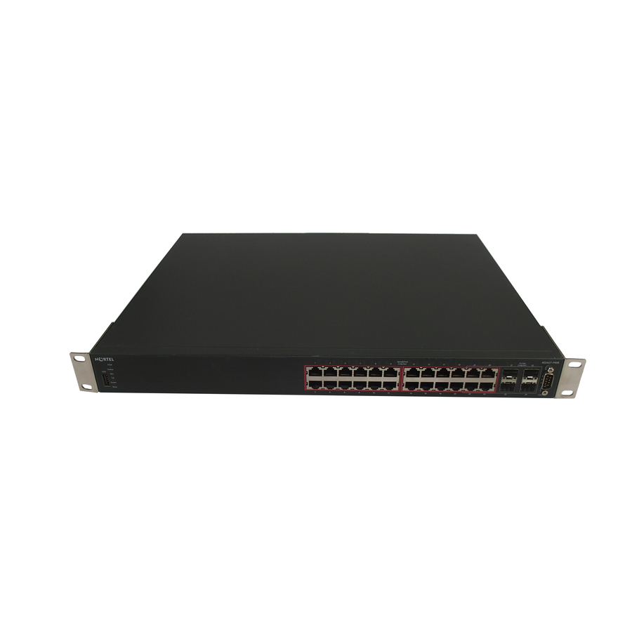
Checking Light Emitting Diode (LED) on the Nortel Ethernet Routing Switch 4500 Series 43 Nortel Ethernet Routing Switch 4526T-PWR 1. USB Port 2. Switch LEDs 3. 10/100 RJ-45 ports (LEDs above ports) Nortel Ethernet Routing Switch 4524GT 1. USB Port 2. -
Page 44: Nortel Ethernet Routing Switch 4500 Series
44 Installing the Nortel Ethernet Routing Switch 1. USB Port 2. Switch LEDs 3. XFP slots Nortel Ethernet Routing Switch 4526GTX-PWR 1. USB Port 2. Switch LEDs 3. XFP slots Switch LED state indicators "Switch LED state indicators" (page 44) state indications provided by LED color and fluctuation cues. -
Page 45: Nortel Ethernet Routing Switch 4500 Series
Checking Light Emitting Diode (LED) on the Nortel Ethernet Routing Switch 4500 Series 45 Label Status Down Base Port LED state indicators This section describes the port LED state indicators by color and fluctuation cues. The following list describes the three port LEDs: •... -
Page 46: Nortel Ethernet Routing Switch 4500 Series
46 Installing the Nortel Ethernet Routing Switch • Speed indicates the port speed (for example, 10 Mb/s, 100 Mb/s, 1000 Mb/s). Table 16 RJ-45 Port LED state indicators Label Color and Status Speed/PoE Green, Pulse Green–Green Green, Steady Amber, Pulse Amber–Amber... -
Page 47: Nn47205-300 (322811-B) 03.01 Standard
Setting IP parameters for the Nortel Ethernet Routing Switch 4500 Series 47 Setting IP parameters for the Nortel Ethernet Routing Switch 4500 Series After a Nortel Ethernet Routing Switch 4500 Series switch starts up and initializes all software modules, it begins switching operations. -
Page 48: Nortel Ethernet Routing Switch 4500 Series
48 Installing the Nortel Ethernet Routing Switch Property Data Bits Stop Bits Parity Flow Control You require a console cable and connector to match the male DTE connector (DB-9) on the switch to connect the terminal to the switch console port. -
Page 49: Nortel Ethernet Routing Switch 4500 Series
Setting IP parameters for the Nortel Ethernet Routing Switch 4500 Series 49 Basic switch parameters have now been configured and saved. Nortel Ethernet Routing Switch 4500 Series console port supports Nortel CLI only. When the switch is set to factory default parameters, the CLI Quickstart displays. -
Page 50: Nortel Ethernet Routing Switch 4500 Series
Setting IP parameters using IP.CFG file on a USB memory device If the swtich does not obtain an IP address using bootp, and, a file named IP.CFG exists on the USB memory device, then the switch loads the IP.CFG file as its configuration. -
Page 51: Nortel Ethernet Routing Switch 4500 Series
USB drive. The action will be silent. Also, users attached to the serial console during factory default reboot will observe the Nortel Logo page only, and should NOT attempt to access the switch for at least 3 minutes after the logo screen is displayed. -
Page 52: Nortel Ethernet Routing Switch 4500 Series
Setting IP parameters using bootp The Nortel Ethernet Routing Switch 4500 Series switches are configured to obtain a management IP address using BOOTP by default If the switch is connected to the network and an appropriate bootp server is configured, then the server assigns an IP address to the switch. -
Page 53: Nortel Ethernet Routing Switch 4500 Series
Setting IP parameters for the Nortel Ethernet Routing Switch 4500 Series 53 IP configuration screen Use the fields on the IP configuration screen to configure the IP parameters. All fields are divided into three columns: Configurable, In Use, and Last BootP. Use the Configurable column to configure a new value for the field. -
Page 54: Nn47205-300 (322811-B) 03.01 Standard
Stack connector The stack connector is a component of the Nortel Ethernet Routing Switch 4500 Series back panel and consists of the Unit Select switch, Cascade Down connector, and Cascade Up connector. The stack connector is... -
Page 55: Nortel Ethernet Routing Switch 4500 Series
You can designate only one switch in a stack as the base unit; that is, with the switch in the base unit position. For all other switches in the stack, the Unit Select switch must be in the left position. -
Page 56: Nortel Ethernet Routing Switch 4500 Series
56 Installing the Nortel Ethernet Routing Switch Simplified stacking diagram "Connecting cascade cables" (page 56) connection configuration. Failure to use this configuration can result in loss of connectivity. Connecting cascade cables 1. Base Unit 2. Cascade Cable (connected from Base Unit Cascade Down connector to Unit 2 Cascade Up connector) NN47205-300 (322811-B) 03.01 Standard... -
Page 57: Nortel Ethernet Routing Switch 4500 Series
Stack MAC address When a switch participates in a stack configuration, a stack MAC address is automatically assigned during stack initialization. The stack MAC address is the base unit MAC address plus 1. If another unit in the stack is assigned as the base unit, the new stack MAC address is the MAC address of the new base unit plus 1. -
Page 58: Nn47205-300 (322811-B) 03.01 Standard
58 Installing the Nortel Ethernet Routing Switch Redundant cascade stacking The Nortel Ethernet Routing Switch 4500 Series allows a stack of up to eight units into a dual-path cascade stack. If any single unit fails, or if a cable is accidently disconnected, other units in the stack remain operational. -
Page 59: Nortel Ethernet Routing Switch 4500 Series
Automatic Unit Replacement (AUR) for both configuration and software is enabled for all Nortel Ethernet Routing Switch 4500 Series platforms and software releases. This means that the agent code image, on a replacement unit, is automatically upgraded or downgraded to match the software running on the stack. -
Page 60: Nortel Ethernet Routing Switch 4500 Series
(stack up) or cascade down (stack down). This designation depends on the stack cabling arrangement. Nortel recommends that you use Cascade Down configuration. (see Cascade down In a cascade down configuration, the base unit is located at the top of the... -
Page 61: Nortel Ethernet Routing Switch 4500 Series
3. Cascade Cable 4. Cascade Cable Since many network management software packages assume a cascade down (stack down) configuration, Nortel recommends that you use a cascade down configuration. Cascade up In a cascade up (stack up) configuration, the base unit is physically the top unit in the stack. -
Page 62: Nortel Ethernet Routing Switch 4500 Series
3. Cascade Down connector with cable connected 4. Cascade Cable Because many network management software packages use a cascade down (stack down) configuration, Nortel recommends that you use a cascade down configuration. (See The following guidelines apply for stack configuration: •... -
Page 63: Nortel Ethernet Routing Switch 4500 Series
You can attach an RS-232 communications cable to the console port of any switch in the stack to establish a console connection. • You can perform a software upgrade on the stack from any switch using a Telnet session, the Web-based Management Interface, or any SNMP-based management software. -
Page 64: Nortel Ethernet Routing Switch 4500 Series
64 Installing the Nortel Ethernet Routing Switch You must enter a ’.’ on a line by itself to end recording of NUQC commands. The $ sign must be used as a wildcard when specifying unit numbers as a part of any comment which uses port numbers. -
Page 65: Nn47205-300 (322811-B) 03.01 Standard
When you mount this device in a rack, do not stack units directly on top of one another. You must secure each unit to the rack with appropriate mounting brackets. Mounting brackets cannot support multiple units. ATTENTION ATTENTION ATTENTION ATTENTION Nortel Ethernet Routing Switch 4500 Series Installation Guide 5.1 19 November 2007... -
Page 66: Nortel Ethernet Routing Switch 4500 Series
If you are not installing a module in the slot, be sure to keep the metal cover plate in place over the slot. Removing the cover plate impedes airflow and proper cooling of the unit. ATTENTION ATTENTION ATTENTION Nortel Ethernet Routing Switch 4500 Series Installation Guide 5.1 19 November 2007... -
Page 67: Nortel Ethernet Routing Switch 4500 Series
Disconnecting the AC power cord is the only way to turn off AC power to this device. Always connect the AC power cord in a quickly and safely accessible location in case of an emergency. Nortel Ethernet Routing Switch 4500 Series Installation Guide 5.1 19 November 2007... -
Page 68: Nortel Ethernet Routing Switch 4500 Series
DANGER Use only power cords that have a grounding path. Without a proper ground, a person who touches the switch is in danger of receiving an electrical shock. Lack of a grounding path to the switch can result in excessive emissions. -
Page 69: Nortel Ethernet Routing Switch 4500 Series
Pericolo: Utilizzare esclusivamente cavi di alimentazione dotati di un percorso per la messa a terra. Senza un’adeguata messa a terra, chiunque tocchi lo switch corre il rischio di ricevere una scossa elettrica. L’assenza di un percorso per la messa a terra verso lo switch può... -
Page 70: Nortel Ethernet Routing Switch 4500 Series
SFP removal 27 Shelf installation 21 Stack configuration 54 Switch LEDs 40 Switch platforms Table installation 21 Translations of safety messages 65 USB ports 35 Nortel Ethernet Routing Switch 4500 Series Installation Guide NN47205-300 (322811-B) 03.01 Standard 5.1 19 November 2007... -
Page 72: Nortel Ethernet Routing Switch 4500 Series
Sourced in Canada, India, and the United States of America The information in this document is subject to change without notice. Nortel Networks reserves the right to make changes in design or components as progress in engineering and manufacturing may warrant.
Need help?
Do you have a question about the 4524GT and is the answer not in the manual?
Questions and answers