
Related Manuals for Bil-Jax COUGAR LIFT XLT-1571AC


Summary of Contents for Bil-Jax COUGAR LIFT XLT-1571AC
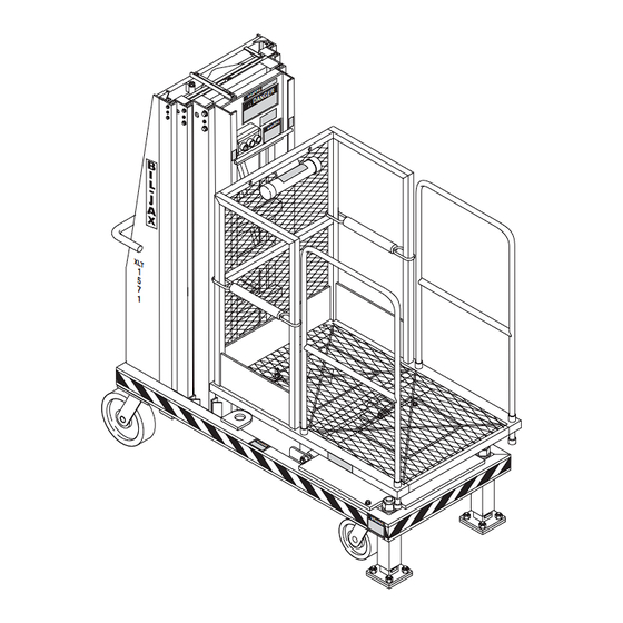
- Page 1 Model XLT-1571AC Operation and Maintenance Manual AERIAL WORK PLATFORMS Electric Hydraulic Lift Platform B33-01-0062...
- Page 2 TELESCOPIC PERSONNEL LIFT This equipment is designed and manufactured in compliance with the duties, re- sponsibilities, and standards set forth for manufacturers in the ANSI 92.3 standard in effect at the time of manufacture. This equipment will meet or exceed applicable OSHA codes and ANSI A92.3 stan- dards when used in accordance with sections 5, 6, 7, 8, 9 &...
-
Page 3: Table Of Contents
Table of Contents Safety........................1-1 Introduction..................1-1 Before Operation ................1-3 During Operation ................1-4 Maintenance Safety................1-6 Damaged Equipment Policy .............1-6 Introduction.....................2-1 General Description ................2-1 Specifications..................2-2 Warranty .....................2-2 Operation ......................3-1 Operator Controls ................3-1 Normal Operating Procedure ............3-2 Emergency Lowering Procedure ............3-3 Maintenance ....................4-1 Scheduled Service Checks ..............4-1 Lubrication..................4-3 Hydraulic System................4-5 Electrical System ................4-11... - Page 4 List of Illustrations Figure 3-1. Lower Control Box................. 3-1 Figure 3-2. Upper Control Box ................. 3-2 Figure 3-3. Emergency Lowering Valve..............3-3 Figure 4-1. Lift Chain Lubrication................4-3 Figure 4-2. Caster Lubrication .................. 4-4 Figure 4-3. Pressure Relief Valve Adjustment............4-6 Figure 4-4.
- Page 5 List of Tables Table 1-1. Minimum Safe Approach Distances ............1-4 Table 2-1. Specifications ..................2-2 Table 4-1. Daily/Weekly Service Checks..............4-1 Table 4-2. Monthly Service Checks .................4-2 Table 4-3. Troubleshooting Chart ................4-15 Table 5-1. Replacement Decals ................5-1 Table 6-1. Top Mast Parts List .................6-3 Table 6-2.
-
Page 7: Safety
The information contained herein is not to be considered as legal advice and is intended for informational purposes only. This information is offered to alert Bil-Jax customers procedures that may be of concern to them. This information is not intended to be all inclusive and is to be followed in the use of Bil-Jax equipment only. - Page 8 XLT-1571AC Safety Notes This manual contains DANGERS, WARNINGS, CAUTIONS, and NOTES that must be followed to prevent the possibility of improper service, damage to the equipment, or per- sonal injury. DANGER Dangers warn of equipment operation near electrical power lines that could lead to personal injury or death.
-
Page 9: Before Operation
1 — SAFETY BEFORE OPERATION Ensure the following general safety precautions are followed before operating the Cougar Lift. • ALWAYS survey the usage area for potential hazards such as untampered earth fills, unlevel surfaces, overhead obstructions, and electrically charged conduc- tors or wires. -
Page 10: During Operation
XLT-1571AC DURING OPERATION Ensure the following general safety precautions are followed during the operation of the Cougar Lift. DANGER This machine is not insulated for use near electrical power lines and DOES NOT provide protection from contact with or close proximity to any electrically charged conductor. - Page 11 1 — SAFETY • NEVER allow electrode contact with any part of the platform if welding is be- ing performed by a worker from the platform. • NEVER use without the floor pads fully based on the floor. • NEVER override or by-pass manufacturer's safety devices. •...
-
Page 12: Maintenance Safety
(this damage may be internal and is not always visi- ble to the naked eye), Bil-Jax requires that the lift be returned to our facility at 125 Tay- lor Parkway, Archbold, Ohio, for reconditioning. If you have any questions concerning what constitutes structural damage, please call the Bil-Jax Service Department at 800-537-0540. -
Page 13: Introduction
Introduction GENERAL DESCRIPTION The model XLT-1571 Cougar Lift is designed and manufactured for use as a warehouse stocking and order picking machine. Its unique guard rail design per mits the operator to ride on the platform with the load, while transferring it from group level to its overhead storage location. -
Page 14: Specifications
This warranty does not apply if the lift and/or its component parts have been altered, changed, or repaired without the consent of Bil-Jax or by anyone other than Bil-Jax or its factory trained personnel, nor if the lift and/or its components have been subjected to misuse, negligence, accident or any conditions deemed other than those considered as occurring during normal use. -
Page 15: Operation
Operation OPERATOR CONTROLS The operator controls for the Cougar Lift are contained on the upper and lower control boxes. Lower Control Box The lower control box is located on the front of the base platform and contains 3 pushbutton controls, , and EMERGENCY STOP WHEEL DOWN... -
Page 16: Normal Operating Procedure
XLT-1571AC Upper Control Box The upper control box is located on the back of the top mast and is accessible from the platform. The upper control box contains 3 controls, selector switch, DOWN pushbutton, and pushbutton. The controls on the upper control box EMERGENCY STOP are used to raise and lower the unit. -
Page 17: Emergency Lowering Procedure
3 — OPERATION The lift is now ready for operation. While depressing the pushbutton, select the desired function, on the position selector switch. The platform DOWN will raise or lower respectively. The pushbutton deactivates EMERGENCY STOP the control circuit. NOTE: Should the platform continue to rise after the switch is released, press pushbutton and select the... - Page 18 XLT-1571AC...
-
Page 19: Maintenance
Maintenance SCHEDULED SERVICE C HECKS Daily/Weekly Service Checks Perform the following daily/weekly service checks as listed in Table 4 Table 4-1. Daily /Weekly Service Chec aily Service Check before use Weekly Ensure Operation Manual is located in manual tube. Check chain assemblies for split leaves, loose pins, excessive wear, or elongation. -
Page 20: Table 4-2. Monthly Service Checks
XLT-1571AC Monthly Service Checks Perform the following monthly service checks as listed in Table 4-2. Table 4-2. Monthly Service Checks Every Every Every Every Service Check month 6 months 12 months 48 months Check hydraulic raise valve operation. Check operation of manual emergency lowering valve. -
Page 21: Lubrication
4 — MAINTENANCE LUBRICATION Lubrication makes operation of the Cougar Lift more efficient and extends the life of the unit. Perform the following lubrication procedures. Oil lift chains with clean 40W oil weekly or as needed. Refer to Figure 4-1. LIFT CHAINS LIFT... -
Page 22: Figure 4-2. Caster Lubrication
XLT-1571AC Grease all caster axles and swivel raceways at the 2 grease fittings on each caster semiannually with wheel bearing grease. Refer to Figure 4-2. Figure 4-2. Caster Lubrication NOTE: The plastic slide blocks in the mast are made of a bearing material which has a high degree of lubricity and need only be kept clean. -
Page 23: Hydraulic System
4 — MAINTENANCE HYDRAULIC SYSTEM Hydraulic system maintenance varies by the amount of use and the environment in which the lift is used. Constant attention to keep the oil clean and the reservoir properly filled will help prevent possible damage to the system. Hydraulic System Inspection Check all hydraulic hoses and fittings for leaks and damage daily. -
Page 24: Figure 4-3. Pressure Relief Valve Adjustment
XLT-1571AC Pressure Relief Valve Reset Perform the following procedure to reset the pressure relief valve. Refer to Figure 4-3. Disconnect the hydraulic hose from the main pressure port. Install a 4000 psi gauge into the main pressure port in the pump unit. CAUTION Do not adjust the pressure relief valve higher than 2100 psi. -
Page 25: Figure 4-4. Flow Restrictor Valve
4 — MAINTENANCE Flow Restrictor Valve Replacement If the flow restrictor valve Figure 4-4 needs to be removed or replaced, it is important that it be properly reinstalled. The valve will be marked either with an arrow or with the word “IN”. -
Page 26: Figure 4-5. Raise Valve Operation Check
XLT-1571AC Raise Valve Operation Check The raise valve is a normally open (N.O.) valve in the hydraulic system. Perform the fol- lowing procedures to check the operation of the raise valve. Disconnect the black and yellow wires from the solenoid, to the valve at the wire connector, Figure 4-5. - Page 27 Hydraulic Cylinder Repair CAUTION Removing the hydraulic cylinder from the Cougar Lift requires major disassem- bly of the unit. Contact Bil-Jax before removing the hydraulic cylinder from the unit for assistance. Hydraulic Cylinder Removal It is recommended that Bil-Jax be contacted for assistance before removing the hydraulic cylinder.
-
Page 28: Figure 4-6. Hydraulic Cylinder Exploded View
XLT-1571AC nut (3) and install in groove. Install rod wiper (2) into the top of the gland nut (3). Place gland nut (3) complete with a new gland nut seal (4), rod wiper (2), and o- ring (5) onto the cylinder and tighten down. Reinstall the hydraulic cylinder into the unit and reconnect the hydraulic hose. -
Page 29: Electrical System
4 — MAINTENANCE ELECTRICAL SYSTEM Regular maintenance is necessary to keep the electrical system in proper working order. Check daily all electrical wires for cuts, broken wires, potential short circuits, and any other damage. 4-11... -
Page 30: Lift Chains And Slide Blocks
XLT-1571AC LIFT CHAINS AND SLIDE BLOCKS WARNING Do not operate a unit on which any chain assembly is damaged or in need of re- placement. Operating a unit with a damaged chain can cause severe injury or death to personnel and damage to equipment. Inspect all lift chains daily. -
Page 31: Figure 4-8. Lift Chain Adjustment
4 — MAINTENANCE Lift Chain Adjustment Raise the platform to the maximum extended height and then lower it while someone checks to see that all sheaves are turning and checks for chain damage or wear. After the platform is completely lowered, remove the plexiglass cover from the base. -
Page 32: Figure 4-9. Slide Block Adjustment
XLT-1571AC Slide Block Adjustment Annually check for wear on the slide blocks and replace or retighten as necessary. If the lift exhibits excessive mast sway, it is probable that the slide blocks need adjustment. The slide blocks should be adjusted so that there is no air gap between the slide block and the mast the slide block is moving against. -
Page 33: Troubleshooting
4 — MAINTENANCE TROUBLESHOOTING Table 4-3. Troubleshooting Chart Problem Cause Correction 1. Green Base not firmly set on footpads. Depress button WHEEL UP BASE SET WHEEL UP BASE SET button will not light. raising front casters. This allows lift to firmly set on footpads. b. - Page 34 XLT-1571AC Table 4-3. Troubleshooting Chart, Continued Problem Cause Correction 4. Pump/motor will not run button is activated Turn button coun- EMERGENCY STOP EMERGENCY STOP when is selected. (pushed in). terclockwise to de-activate. b. Green button is b. Refer to Problem 1. WHEEL UP BASE SET not lit.
-
Page 35: Replacement Decals
Refer to Table 5-1, and Figures 5-1, 5-2, and 5-3 for descriptions and locations of decals on the Cougar Lift. Table 5-1. Replacement Decals Decal No. Description of Decal B06-00-0003 Bil-Jax ID Number (Not available as replacement part) B06-00-0009 Warning...Moving telescopic masts will create... B06-00-0034 Danger...During charging, explosive oxyhydrogen gas... B06-00-0106 XLT-1571 (Transfer type decal) B06-00-0138 Warning...(Maintenance decal) -
Page 36: Figure 5-1. Replacement Decals
XLT-1571AC B06-00-0306 B06-00-0228 B06-00-0170 B06-00-0034 B06-00-0350 Fall protection equipment must be used at all times during operation. Failure to wear fall protection equipment may allow operator to fall from platform resulting in serious B06-00-0339BLT UTT/ATT B06-00-0339BLT B06-00-0339 B06-00-0349 B06-00-0295 B06-00-0173 B06-00-0175 B06-00-0106 B06-00-0138... -
Page 37: Figure 5-2. Decal Locations, Side View
5 — REPLACEMENT DECALS 0009 0146 0170 0339 OR 0339BLT 0173 0173 0455 0192 0106 0291 0170 0225 0167 AROUND COMPLETE BASE ON ALL SIDES 0306 Figure 5-2. Decal Locations, Side View... -
Page 38: Figure 5-3. Decal Locations, Front View
XLT-1571AC 0009 0228 0295 0455 0175 0138 0350 0349 INSIDE DOOR 0106 0286 0034 0003 ON CHARGER INSIDE 0289 0167 ON RESERVOIR INSIDE AROUND COMPLETE BASE ON ALL SIDES Figure 5-3. Decal Locations, Front View... -
Page 39: Parts List
Parts List... -
Page 40: Top Mast Parts List
XLT-1571AC TOP MAST PARTS LIST Refer to Table 6-1 for the parts list for the top mast. 24 23 Figure 6-1. Top Mast Exploded View... -
Page 41: Table 6-1. Top Mast Parts List
6 — PARTS LIST Table 6-1. Top Mast Parts List Item No. Part No. Description B16-01-0024 Top Mast Weldment 0090-0014 Screw, 1/4-20 x 2-1/4 in. B01-09-0026 Grommet, Plastic B29-00-0076 Bracket, Outreach 0090-0181 Nut, Lock, 8-32 0090-0813 Screw, 8-32 x 3/4 in. B01-02-0059 Box, Control, Upper B40-00-0003... -
Page 42: Center Mast Parts List
XLT-1571AC CENTER MAST PARTS LIST Refer to Table 6-2 for the parts list for the center mast. Figure 6-2. Center Mast Exploded View... -
Page 43: Table 6-2. Center Mast Parts List
6 — PARTS LIST Table 6-2. Center Mast Parts List Item No. Part No. Description B16-01-0020 Center Mast Weldment 0090-0770 Pin, Cotter 3/16 x 1-1/2 in. B36-01-0002 Sheave Axle 0090-0425 Washer, 5/8 in. B26-00-0009 Chain Sheave Assembly 0090-0389 Screw, Adjustment, 1/2-20 x 1/2 in. 0090-0403 Screw, #10 x 1 in. -
Page 44: Lower Mast Parts List
XLT-1571AC LOWER MAST PARTS LIST Refer to Table 6-3 for the parts list for the lower mast. Figure 6-3. Lower Mast Exploded View... -
Page 45: Table 6-3. Lower Mast Parts List
6 — PARTS LIST Table 6-3. Lower Mast Parts List Item No. Part No. Description B16-01-0021 Lower Mast Weldment 0090-0770 Pin, Cotter 3/16 x 1-1/2 in. B36-01-0002 Sheave Axle 0090-0425 Washer, Flat, 5/8 in. B26-00-0009 Chain Sheave Assembly 0090-0188 Nut, Lock, 3/8-16 0090-0422 Washer, Flat, 3/8 B40-00-0003... -
Page 46: Rear Compartment Parts List
XLT-1571AC REAR COMPARTMENT PARTS LIST Refer to Table 6-4 for the parts list for the rear compartment. Figure 6-4. Rear Compartment Exploded View... -
Page 47: Table 6-4. Battery Compartment Parts List
6 — PARTS LIST Table 6-4. Battery Compartment Parts List Item No. Part No. Description B11-01-0087 Base Weldment 0090-0344 Screw, Threadcut, 10-24 x 1/2 in. B01-10-0003 Receptacle, Flush Mount 0090-0813 Screw, 8-32 x 3/4 in. B19-00-0022 Box, Black, TomCat 0090-0415 Washer, Flat, #10 0090-0181 Nut, Lock, 8-32... -
Page 48: Hydraulic Pump Compartment Parts List
XLT-1571AC HYDRAULIC PUMP COMPARTMENT PARTS LIST Refer to Table 6-5 for the parts list for the hydraulic pump compartment. Figure 6-5. Hydraulic Pump Compartment Exploded View 6-10... -
Page 49: Table 6-5. Hydraulic Pump Compartment Parts List
6 — PARTS LIST Table 6-5. Hydraulic Pump Compartment Parts List Item No. Part No. Description B11-01-0087 Base Weldment B05-00-0006 Tape, Foam Adhesive 2 ft. 0090-0183 Nut, Lock, 1/4-20 0090-0005 Bolt, 1/4-20 x 3/4 0090-0419 Washer, Flat, 1/4 in. B29-00-0116 Bracket, Hydraulic Valve 0090-0014 Bolt, 1/4-20 x 2-1/2 in. -
Page 50: Upper Base Parts List
XLT-1571AC UPPER BASE PARTS LIST Refer to Table 6-6 for the parts list for the upper base. 15 16 Figure 6-6. Upper Base Exploded View 6-12... -
Page 51: Table 6-6. Upper Base Parts List
6 — PARTS LIST Table 6-6. Upper Base Parts List Item No. Part No. Description B11-01-0087 Base Weldment 0090-0344 Screw, Threadcut, 10-24 x 1/2 in. B07-01-2003 Edge, Top Cover B05-00-0006 Tape, Foam Adhesive 32 in. B18-00-0108 Plexiglass, 1/8 in. B24-01-0009 Frame, Aluminum B01-02-0058 Box, Control, Lower... -
Page 52: Base Mast Parts List
XLT-1571AC BASE MAST PARTS LIST Refer to Table 6-7 for the parts list for the base mast. Figure 6-7. Base Mast Exploded View 6-14... -
Page 53: Table 6-7. Base Mast Parts List
6 — PARTS LIST Table 6-7. Base Mast Parts List Item No. Part No. Description 0090-0188 Nut, Lock, 3/8-16 0090-0422 Washer, Flat, 3/8 in. B40-00-0003 Cable 0090-0389 Screw, Adjustment, 1/2-20 x 1/2 in. 0090-0403 Screw, #10 x 1 in. B31-00-0001 Slide Block, Plastic B01-01-0046 Cord, Retractable... -
Page 54: Lower Base Parts List
XLT-1571AC LOWER BASE PARTS LIST Refer to Table 6-8 for the parts list for the lower base. Figure 6-8. Lower Base Exploded View 6-16... -
Page 55: Table 6-8. Lower Base Parts List
6 — PARTS LIST Table 6-8. Lower Base Parts List Item No. Part No. Description 0090-0344 Screw, Threadcut, 10-24 x 1/2 in. B18-00-0107 Cover 0090-0344 Screw, Threadcut, 10-24 x 1/2 in. B04-07-0015 Clamp, Cable B01-01-0123 Cable Assembly, Mast Switch B01-03-0040 Switch, Limit, Mast 0090-0770 Pin, Cotter... -
Page 56: Platform Parts List
XLT-1571AC PLATFORM PARTS LIST Refer to Table 6-9 for the parts list for the platform. 19, 20 Figure 6-9. Platform Exploded View 6-18... -
Page 57: Table 6-9. Platform Parts List
6 — PARTS LIST Table 6-9. Platform Parts List Item No. Part No. Description B17-00-0087 Platform Weldment 0090-0051 Bolt, 3/8-16 x 2-3/4 in. 0090-0210 Washer, Lock, 3/8 in. 0090-0162 Nut, 3/8-16 0068-061 Pin, Snap B01-03-009 Switch, Limit B01-10-0002 Alarm, Audible B01-10-0004 Light 0090-0802... -
Page 58: 6-10 Hydraulic Unit Parts List
XLT-1571AC 6-10 HYDRAULIC UNIT PARTS LIST Figure 6-10. Hydraulic Unit Assembly 6-20... -
Page 59: Table 6-10. Hydraulic Unit Parts List
6 — PARTS LIST Table 6-10. Hydraulic Unit Parts List Item No. Part No. Description B02-15-0088 Bolt, 5/16-24 x 2.75 Torx B02-15-0119 Coupler, 9T-20-40 B02-02-0087 Plug, #6 ORM B02-15-0128 Ball, Steel B02-15-0091 Seal, Shaft B02-15-0006 Washer B02-15-0061 Magnet, Plumbing B02-15-0121 Filter B02-15-0125 Cover, Suction... -
Page 60: 6-11 Hydraulic Fittings And Hoses Diagram
XLT-1571AC 6-11 HYDRAULIC FITTINGS AND HOSES DIAGRAM Figure 6-11. Hydraulic Fittings and Hoses Diagram 6-22... -
Page 61: Table 6-11. Hydraulic Fittings And Hoses Parts List
6 — PARTS LIST Table 6-11. Hydraulic Fittings and Hoses Parts List Item No. Part No. Description B02-03-0018 Cylinder, Hydraulic Lift, 1.5 in. Diameter B02-02-0002 Fitting, 4JIC-4NPT 90°, 2501-4 B02-04-0002 Valve, Flow Control, 1.25 in. B02-02-0041 Fitting, 4NPT-4NPT 90° B02-01-0110 Hose, Hydraulic, 22 in., 4M3K W/2 4-4FJX B02-05-0011 Pump, Hydraulic, Standard AC... -
Page 62: 6-12 Hydraulic Fittings And Hoses Schematic
XLT-1571AC 6-12 HYDRAULIC FITTINGS AND HOSES SCHEMATIC Figure 6-12. Hydraulic Fittings and Hoses Schematic 6-24... -
Page 63: 6-13 Electrical Diagram
6 — PARTS LIST 6-13 ELECTRICAL DIAGRAM 1571/1071 Schematic Lower Lift Lower 110v Option Flush Mt Control Recp. Switcher Board E-Stop Wheel Up E-Stop Down Wheel Wheel Down Upper Control E-Stop Beeper Lift Valve Light Down E-Stop Down Valve Pump Start Wheel Valve... -
Page 64: Figure 6-14. Electrical Layout Diagram
XLT-1571AC Figure 6-14. Electrical Layout Diagram 6-26... -
Page 65: Ansi Reprint
ANSI Reprint The following sections are reprinted from the ANSI A92.3-1990 code in effect at the time of manufacture. Permissi on to reprint has been granted by the Scaffold Industry Association. 5. Responsibilities of Dealers 5.1 Basic Principles. Sound principles of safety, training, inspection, maintenance, applications, and operation consistent with all data available regarding the parameters intended use and expected environment shall be applied in the training of operators, in... - Page 66 XLT-1571AC 5.9 Record Retention. Dealer(s) shall retain the following records for at least 3 years: (1) Name and address of the purchaser of each aerial platform by serial number and the date of delivery (2) Records of the person(s) trained upon each delivery of an aerial platform (3) Records of the predelivery preparation performed prior to each delivery.
- Page 67 7 — ANSI REPRINT 6.6 Maintenance Safety Precautions. Before adjustments and repairs are started on an aerial platform, the following precautions shall be taken as applicable: (1) All controls in the "off" position and all operating features secured from inadvertent motion by brakes, blocks, or other means (2) Powerplant stopped and starting means rendered inoperative (3) Platform lowered to the full down position, if possible, or otherwise secured by blocking or cribbing to prevent dropping (4) Hydraulic oil pressure relieved from all...
- Page 68 XLT-1571AC 7.2 Manuals. Users shall keep and maintain copy(ies) of the operating and maintenance manual(s) required in 4.17 of this standard. The operating manual(s) shall be stored in the location required in 4.18 of this standard. These manuals are considered an integral part of the aerial platform and are vital to communication of necessary safety information to users and operators.
- Page 69 7 — ANSI REPRINT 7.7 Before Operation. Before authorizing an operator to operate an aerial platform, the user shall ensure that the operator has: (1) Been instructed by a qualified person in the intended purpose and function of each control (2) Read and understood the manufacturer's operating instructions and user's safety rules, or been trained by a qualified person on the contents of the manufacturer's operating instructions and user's safety rules (3) Understood by reading or by having a qualified person explain all...
- Page 70 XLT-1571AC 7.11.8 Fueling. The engine shall be shut down while fuel tanks are being filled. Fueling shall be done in a well-ventilated area free of flame, sparks, or other hazards that may cause fire or explosion. 7.11.9 Battery Charging. Batteries shall be charged in a well-ventilated area free of flame, sparks, or other hazards that may cause fire or explosion.
- Page 71 7 — ANSI REPRINT operator shall be familiar with the manuals stored on the aerial platform and consult them when questions arise with respect to the aerial platform. 8.3 Prestart Inspection. Before use each day or at the beginning of each shift, the aerial platform shall be given a visual inspection and functional test including but not limited to the following: (1) Operating and emergency controls (2) Safety devices (3) Personal protective devices, including fall protection (4) Air, hydraulic, and fuel system...
- Page 72 XLT-1571AC 8.10.1 Personnel Footing. Personnel shall maintain a firm footing on the platform floor while working thereon. Use of planks, ladders, or any other devices on the aerial platform for achieving additional height or reach shall be prohibited. 8.10.2 Other Moving Equipment. When other moving equipment or vehicles are present, special precautions shall be taken to comply with local ordinances or safety standards established for the workplace.
- Page 73 7 — ANSI REPRINT 9.1 Basic Principles. Sound principles of safety, training, inspection, maintenance, application, and operation consistent with all data available regarding the parameters of intended use and expected environment shall be applied in the performance of responsibilities of lessors with due consideration of the knowledge that the unit shall be carrying personnel.
- Page 74 XLT-1571AC M.S.A.D. = Minimum Safe Approach Distance (See Table 7-1). DENOTES PROHIBITED ZONE • Do not allow machine, personnel, or conductive materials inside prohibited zone. • Maintain M.S.A.D. from all energized lines and parts as well as those shown. • Assume all electrical parts and wires are energized unless known otherwise. Diagrams shown are only for purposes of illustrating M.S.A.D.
-
Page 75: Table 7-1. Minimum Safe Approach Distance (M.s.a.d.) To Energized
7 — ANSI REPRINT Table 7-1. Minimum Safe Approach Distance (M.S.A.D.) to energized (exposed or insulated) power lines and parts. Minimum Safe Approach Distance Voltage Range (Feet) (Meters) (Phase to Phase) 0 to 300V Avoid Contact Over 300V to 50KV 3.05 Over 50KV to 200KV 4.60... - Page 76 XLT-1571AC 7-12...
- Page 78 125 Taylor Parkway Archbold, OH 43502 Phone (419) 445-8915 (800) 537-0540 (419) 445-0367...
Need help?
Do you have a question about the COUGAR LIFT XLT-1571AC and is the answer not in the manual?
Questions and answers