
Related Manuals for Mitsubishi Electric MELFA


Summary of Contents for Mitsubishi Electric MELFA
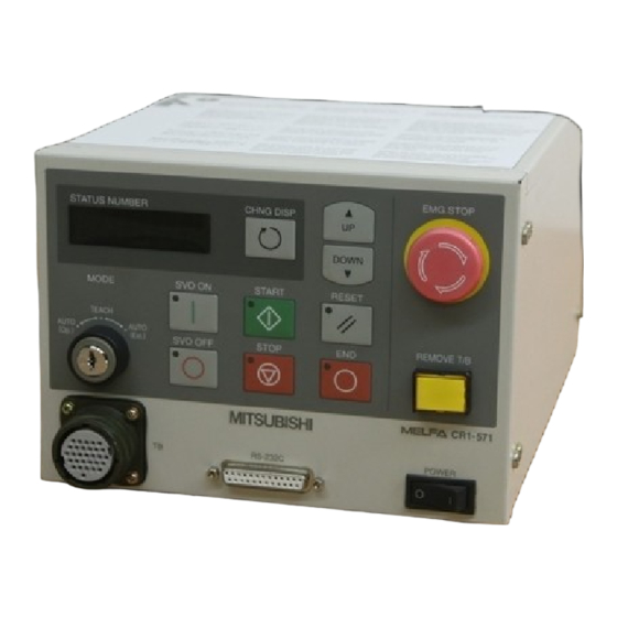
- Page 1 MITSUBISHI ELECTRIC MELFA Industrial Robot Hardware Manual CR1 Controller Art.No.: 133799 2001 05 22 BFP-A8054-D MITSUBISHI ELECTRIC INDUSTRIAL AUTOMATION...
- Page 2 Safety Precautions Always read the following precautions and the separate "Safety Manual" before starting use of the robot to learn the required measures to be taken. CAUTION All teaching work must be carried out by an operator who has received special training. (This also applies to maintenance work with the power source turned ON.) →...
- Page 3 The points of the precautions given in the separate "Safety Manual" are given below. Refer to the actual "Safety Manual" for details. CAUTION Use the robot within the environment given in the specifications. Failure to do so could lead to a drop or reliability or faults. (Temperature, humidity, atmosphere, noise environ - ment, etc.) CAUTION Transport the robot with the designated transportation posture.
- Page 4 C.Precautions for the basic configuration are shown below.(When CR1-571 is used for the controller.) CAUTION Provide an earth leakage breaker that packed together on the primary power supply of the controller as protection against electric leakage. Failure to do so could lead to electric shock accidents. Power supply :Single phase 90-132VAC,180-253VAC.
- Page 5 Revision history Date of print Specifications No. Details of revisions 2000-02-17 BFP-A8054Z-* ・ First print 2000-03-24 BFP-A8054 ・ The earth leakage breaker packaged is added. ・ Writing error correction. 2000-04-11 BFP-A8054-A ・ RP-1AH/3AH/5AH series was added. 2000-06-09 BFP-A8054-B ・ The power supply voltage of CR1 controller was corrected. 2000-12-18 BFP-A8054-C ・...
- Page 6 ・ The information contained in this document has been written to be accurate as much as possible. Please interpret that items not described in this document "cannot be performed.". Please contact your nearest dealer if you find any doubtful, wrong or skipped point. Copyright(C) 2000 MITSUBISHI ELECTRIC CORPORATION...
-
Page 7: Table Of Contents
Contents Page 1 Before starting use ..................................1-1 1.1 Using the instruction manuals ............................1-1 1.1.1 The details of each instruction manuals ........................ 1-1 1.1.2 Symbols used in instruction manual ........................1-3 1.2 Safety Precautions ................................. 1-4 1.2.1 Precautions given in the separate Safety Manual ..................... 1-5 2 Unpacking to installation ................................ - Page 8 Page 5.2 Inspection items ..................................5-44 5.2.1 Daily inspection items ..............................5-44 5.2.2 Periodic inspections ..............................5-44 5.3 Maintenance and inspection procedures ........................5-45 5.3.1 Replacing the battery ..............................5-45 5.4 Maintenance parts ................................. 5-46...
-
Page 9: Before Starting Use
1Before starting use 1 Before starting use This chapter explains the details and usage methods of the instruction manuals, the basic terminology and the safety precautions. 1.1 Using the instruction manuals 1.1.1 The details of each instruction manuals The contents and purposes of the documents enclosed with this product are shown below. Use these documents according to the application. - Page 10 1Before starting use Explains the causes and remedies to be taken when an error occurs. Expla - T r o u b l e - nations are given for each error No. shooting 1-2 Using the instruction manuals...
-
Page 11: Symbols Used In Instruction Manual
1Before starting use 1.1.2 Symbols used in instruction manual The symbols and expressions shown in Table 1-1 are used throughout this User's Manual. Learn the meaning of these symbols before reading this instruction manual. Table 1-1 : Symbols in instruction manual Symbol Meaning Precaution indicating cases where there is a risk of operator fatality or seri -... -
Page 12: Safety Precautions
1Before starting use 1.2 Safety Precautions Always read the following precautions and the separate "Safety Manual" before starting use of the robot to learn the required measures to be taken. CAUTION All teaching work must be carried out by an operator who has received special training. (This also applies to maintenance work with the power source turned ON.) →... -
Page 13: Precautions Given In The Separate Safety Manual
1Before starting use 1.2.1 Precautions given in the separate Safety Manual The points of the precautions given in the separate "Safety Manual" are given below. Refer to the actual "Safety Manual" for details. CAUTION Use the robot within the environment given in the specifications. Failure to do so could lead to a drop or reliability or faults. - Page 14 1Before starting use 1-6 Safety Precautions...
-
Page 15: Unpacking To Installation
2Unpacking to installation 2 Unpacking to installation 2.1 Confirming the products Confirm that the parts shown in the standard configuration of the controller shown in Table 2-1 are enclosed with the purchased product. Users who have purchased options should refer to the separate "Standard Specifications". The primary power supply cable and grounding cable must be prepared by the user. -
Page 16: Installation
2Unpacking to installation 2.2 Installation 2.2.1 Unpacking procedures 1. Open the top of the cardboard box, and remove the instruction manual. Manuals, etc 3. Remove the inner case 2, and remove the controller. Packaging material 2. Remove the inner case, and Controller remove the machine cable. -
Page 17: Installation Procedures
2Unpacking to installation 2.2.3 Installation procedures EMG.STOP STATUS NUMBER CHANG DISP DOWN SVO ON MODE START RESET TEACH AUTO AUTO REMOVE T/B (Op.) (Ext.) SVO OFF STOP 170 or more Fig.2-3 : Installation dimensions [Caution] A fan is installed on the bottom of the controller, so do not remove the rubber legs and install the controller flat on a surface. -
Page 18: Connecting The Power Cable And Grounding Cable
2Unpacking to installation 2.2.4 Connecting the power cable and grounding cable The power supply voltage is classified as follows by the use robot type. The connection of the cable is to proceed in each explanation clause, and do it. *RP-1AH/3AH/5AH series, RV-1A/2AJ series Power supply voltage : Choose 1-phase AC100V or 1-phase AC200V. -
Page 19: Connecting The Power And Grounding Cable
2Unpacking to installation (2) Connecting the power and grounding cable 1) Prepare the 2 power cables and 1 grounding cable (both 2mm or more). 2) Remove the two M4 screws for the power supply terminal block cover on the rear of the controller. 3) Confirm that the primary power is set to the power specifications set in "(1)Setting the power specifications"... -
Page 20: Connecting The External Emergency Stop
2Unpacking to installation 2.2.5 Connecting the external emergency stop Short piece 1 Emergency stop input Short piece 2 Door switch input RG (24G) Emergency stop output Composition of external emergency stop and door switch DOOR EMG. Switch STOP Wire insert Controller rear side ①... -
Page 21: Installing The Option Devices
3Installing the option devices 3 Installing the option devices The T/B can be installed in the power OFF state as described in the separate manual "Robot arm setup and maintenance", or can be installed/removed in the power ON state as described in "4.2.1 Installing and removing the T/B"... - Page 22 3Installing the option devices (2) Removing the RZ386 or RZ387 card 1) Remove the connection cable A connector. RZ386 or RZ387 card RZ386 or RZ387 card RZ386 or RZ387 card RZ386 or RZ387 card Spread the connector Spread the connector Spread the connector Spread the connector fixing latches outward...
- Page 23 3Installing the option devices (3) Installing the pneumatic hand interface or motorized hand interface Install the pneumatic hand interface or motorized hand interface. CNHNDOUT connector CNHNDOUT connector CNHNDOUT connector CNHNDOUT connector Connect both connectors Connect both connectors Connect both connectors Connect both connectors CNHND connector CNHND connector...
-
Page 24: Installing The Expansion Option Box
3Installing the option devices 3.2 Installing the expansion option box The procedures for installing the expansion option box are indicated below. 1) Loosen the four screws from the side of Installation screw (Four positions) the controller, and remove the side plate. - Page 25 3Installing the option devices Installation screw 5) Insert the option card to be mounted (Four positions) into the corresponding slot, and fix with Rail plate the fitting with rail. Lead any required (2 PCS.) cables from the cable lead-out port on the rear side.
- Page 26 3Installing the option devices 3-18 Installing the expansion option box...
-
Page 27: Basic Operations
4Basic operations 4 Basic operations In this chapter, the following items will be explained regarding the basic operations for handling the robot. Handling the controller The functions of the various keys on the controller are explained. Handling the teaching pendant The methods of installing/removing the T/B, and the functions of the various keys are explained. -
Page 28: Functions Of Each Key
4Basic operations 4.1 Handling the controller 4.1.1 Functions of each key <Front> <Front side of operation panel> 7) 4) EMG.STOP STATUS NUMBER CHANG DISP DOWN MODE SVO ON START RESET TEACH AUTO AUTO REMOVE T/B (Op.) (Ext.) SVO OFF STOP Front operation panel 13) 3) Fig.4-1 :... - Page 29 4Basic operations ◇◆◇ What are the operation rights? ◇◆◇ Even when multiple devices, such as a T/B and personal computer, are connected to the controller, the operation at one time is limited to one device. This limited device (has the operation rights) ◇◆◇...
-
Page 30: Handling The T/B
4Basic operations 4.2 Handling the T/B 4.2.1 Installing and removing the T/B By using the "REMOVE T/B" switch, the T/B can be installed and removed while the controller's control power is (1) Installing with the control power OFF Refer to the separate manual "From robot arm setup to maintenance" for details on installing the T/B with the power OFF. -
Page 31: Functions Of Each Key
4Basic operations 4.2.2 Functions of each key 1) [EMG. STOP] switch This is a push-button switch with lock function for emergency stop. DISABLE DISABLE DISABLE DISABLE ENABLE ENABLE ENABLE ENABLE When this switch is pressed, the R28TB R28TB R28TB R28TB servo will turn OFF and the robot will stop immediately regardless of the T/B enable/disable state. - Page 32 4Basic operations 12) [Jog operation] key (12 keys from [-X (J1)] to [+C (J6)] In this manual, these keys are generically called the "jog operation" keys. When JOINT JOG is selected, each axis will rotate, and when XYZ JOG is selected, the robot will move along each coordinate system.
-
Page 33: Turning The Power On And Off
4Basic operations 4.3 Turning the power ON and OFF 4.3.1 Turning the control power ON CAUTION Always confirm the following items before turning the controller power ON. 1) Make sure that there are no operators in the robot operation range. 2) Make sure that the controller and robot arm are securely connected with the machine cable. -
Page 34: Turning The Servo Power On/Off
4Basic operations 4.4 Turning the servo power ON/OFF 4.4.1 Turning the servo power ON (servo ON) DISABLE ENABLE 1) Confirm that the T/B [ENABLE/DISABLE] switch is set to "DISABLE". T/B disable MODE TEACH 2) Confirm that the [MODE] switch on the front of the controller is set to "TEACH"... -
Page 35: Jog Operation
4Basic operations 4.5 Jog operation Refer to the separate manual "Robot arm setup and maintenance" when carrying out jog operation. The following jog operation modes are available. Use these according to the purpose. Table 4-1 : Jog modes Jog mode Main application Explanation JOINT JOG... -
Page 36: Programming
4Basic operations 4.7 Programming The procedures from creating the program to automatic operation are explained in order using a simple procedure as an example. (1) Creation procedures Start Decide the robot operation order, operation path Deciding the operation order (necessity of linear movement), and the work at each operation position (hand open/close, etc). -
Page 37: Creating The Program
4Basic operations 4.7.1 Creating the program (1) Deciding the operation order :Joint movement :Joint movement :Joint movement :Joint movement Wait position Wait position Wait position Wait position :Linear movement :Linear movement :Linear movement :Linear movement :Teaching position :Teaching position :Teaching position :Teaching position Upward position to Upward position to... -
Page 38: Deciding The Operation Position Name
4Basic operations (2) Deciding the operation position name Wait position Wait position Wait position Wait position (PWAIT) (PWAIT) (PWAIT) (PWAIT) Upward position to Upward position to Upward position to Upward position to Upward position to Upward position to Upward position to Upward position to grasping workpiece grasping workpiece... -
Page 39: Describing And Creating The Program
4Basic operations (3) Describing and creating the program ■ Convert the target robot operations and work into commands. Refer to the separate manual "Instruction Manual: Detailed explanations of functions and operations" for details on the commands. Table 4-2 : Commands used Target operation and work Command Example of designation... - Page 40 4Basic operations ◇◆◇ Program format ◇◆◇ The program format is configured of the "line No. command parameter affixed to command" as shown in Fig. 4-8. Example) 1 0 M O V P W A I T Line No. Command Parameter affixed to command The program is executed in order from the line No.
- Page 41 4Basic operations Input the program 10 MOV PWAIT PR:1ST:1 5) Press the [ ↓ ] key three times. PR:1ST:1 LN:0 The cursor will move to the command editing LN:0 line. --NO DATA-- CODE EDIT ↓ Using the cursor PR:1ST:1 PR:1ST:1 LN:0 LN:0 6) Press the [1], [0] and [SPACE] keys.
- Page 42 4Basic operations PR:1ST:1 PR:1ST:1 10) Press the [P] key while holding down the LN:0 LN:0 [CHAR] key, and then release the [CHAR] 10 MOV P 10 MOV key. CODE EDIT CODE EDIT "P" will be input. + (J1) CHAR SPACE PQR Input "P"...
- Page 43 4Basic operations ■ Teach the robot operation position. Set the position with jog operation (Teaching PGET) 1) Move the robot with jog operation, and set the end of the hand to the position for Hand Hand Hand Hand grasping the workpiece. When the position has been set, open and close the hand to confirm that the workpiece can be grasped.
-
Page 44: Confirming The Program
4Basic operations ◇◆◇ Changing between the command editing screen and position editing screen. ◇◆◇ The commands are edited on the command editing screen, and the positions are edited on the position editing screen. To change from the command editing screen to the position editing screen, press the [POS] + [ADD] keys. -
Page 45: Correcting The Program
4Basic operations ◇◆◇ Immediately stopping the robot during operation ◇◆◇ ・ Press the [EMG. STOP] (emergency stop) switch. The servo will turn OFF, and the moving robot will immediately stop. To resume operation, reset the alarm, turn the servo ON, and start step operation. ・... - Page 46 4Basic operations ◇◆◇ Cursor movement ◇◆◇ When the cursor is at a command line display, the command can be edited. When at a line No. display (LN:), the line No. is designated. The cursor is moved with the [ ↑ ], [ ↓ ], [ ← ] and [ → ] keys. ◇◆◇...
- Page 47 4Basic operations ◇◆◇ Correcting a character ◇◆◇ Move the cursor to the right of the incorrect character, and press the [DEL] key to delete in the left direction. Then, input the correct character. The input character will be inserted at the cursor position.
- Page 48 4Basic operations 3) Move the robot to the new wait position with JOINT jog operation. +34.50 +20.00 +80.00 MO.POS(PWAIT ) MO.POS(PWAIT ) 4) Press the [RPL] key while holding down the X: +132.30 X: +132.30 [STEP] key, and release only the [RPL] key. Y: +354.10 Y: -284.10 The buzzer will sound a "beep", and a...
-
Page 49: Start Automatic Operation
4Basic operations (6) Start automatic operation. CAUTION Before starting automatic operation, always confirm the following item. Starting automatic operation without confirming these items could lead to property damage or physical injury. ・ Make sure that there are no operators near the robot. ・... - Page 50 4Basic operations Select the program number 4) Press the [CHNG DISP] switch, and display STATUS NUMBER the "program No." on the STATUS NUMBER CHNG DISP display panel. (A "P" will appear at the head.) Confirm that the program No. targeted for Display the program number automatic operation is displayed.
-
Page 51: Maintenance And Inspection
5Maintenance and Inspection 5 Maintenance and Inspection The maintenance and inspection procedures to be carried out to use the robot for a long time without trouble are described in this chapter. The types and replacement methods of consumable parts are also explained. 5.1 Maintenance and inspection interval Maintenance and inspection are divided into the inspections carried out daily, and the periodic inspections carry out at set intervals. -
Page 52: Inspection Items
5Maintenance and Inspection 5.2 Inspection items The controller inspection items are shown below. Refer to section "Maintenance and Inspection" in the separate manual "Robot arm setup and maintenance", and inspect the robot arm at the same time. 5.2.1 Daily inspection items Carry out daily inspections following the procedures given in Table 5-1. -
Page 53: Maintenance And Inspection Procedures
5Maintenance and Inspection 5.3 Maintenance and inspection procedures The procedures for carrying out periodic maintenance and inspection are described below. Thoroughly comprehend the procedures, and follow the instructions. This work can be commissioned to the Mitsubishi Service Dept. for a fee. (Never disassemble, etc., any of the parts not described in this section.) The maintenance parts required for the maintenance and inspection are shown in section "5.4 Maintenance parts"... -
Page 54: Maintenance Parts
Table 5-3 : Controller consumable part list Part name Type Qty. Usage section Maker Lithium battery ER6 BKO-NC2157H01 Control unit Mitsubishi Electric Table 5-4 : Controller spare part list Part name Type Qty. Usage section Maker Fuse LM16 RZ386 or RZ387 board... - Page 55 MITSUBISHI ELECTRIC Headquarters European Representatives EUROPE GEVA Mitsubishi Electric Europe B.V. AUSTRIA RUSSIA Wiener Straße 89 12/1 Goncharnaya St, suite 3C MITSUBISHI ELECTRIC EUROPE B.V. Gothaer Str. 8 A-2500 Baden RUS-109240 Moscow Phone: +43 (0) 2252 / 85 55 20...