Advertisement
Quick Star t Guide
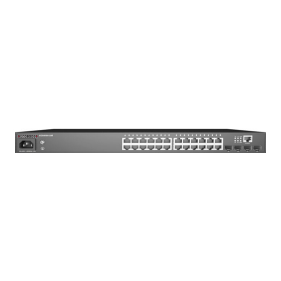
ECS4100 Series Switch
1. Unpack the Switch and Check Contents
Rack Mounting Kit—two brackets and eight screws
Four adhesive foot pads
Power Cord—either Japan, US, Continental Europe
or UK
Console Cable—RJ-45 to DB-9
Documentation—Quick Start Guide (this document)
and Safety and Regulatory Information
Note:
The ECS4100 series switches are for indoor use only.
Note:
For safety and regulatory information, refer to the
Safety and Regulatory Information document included with
the switch.
Note:
Other documentation, including the Web
Management Guide, and CLI Reference Guide, can be
obtained from www.edge-core.com.
2. Mount the Switch
2
1
Attach the brackets to the switch.
2
Use the screws and cage nuts supplied with the rack to
secure the switch in the rack.
*150200001807A_R03*
ECS4100-12T
ECS4100-12PH
ECS4100-28TC
ECS4100-28T
ECS4100-28P
ECS4100-52T
ECS4100-52P
1
– 1 –
Caution:
Installing the switch in a rack requires two
people. One person should position the switch in the rack,
while the other secures it using the rack screws.
Attention:
Deux personnes sont nécessaires pour installer
un commutateur dans un bâti : La première personne va
positionner le commutateur dans le bâti, la seconde va le
fixer avec des vis de montage.
Note:
The switch can also be installed on a desktop or shelf
using the included adhesive rubber foot pads.
3. Ground the Switch
1
2
1
Ensure the rack on which the switch is to be mounted is
properly grounded and in compliance with ETSI ETS 300 253.
Verify that there is a good electrical connection to the
grounding point on the rack (no paint or isolating surface
treatment).
2
Attach a lug (not provided) to a #18 AWG minimum
grounding wire (not provided), and connect it to the
grounding point on the switch using a 3.5 mm screw and
washer. Then connect the other end of the wire to rack
ground.
Caution:
The earth connection must not be removed
unless all supply connections have been disconnected.
Attention:
Le raccordement à la terre ne doit pas être
retiré sauf si toutes les connexions d'alimentation ont été
débranchées.
Caution:
The device must be installed in a restricted-
access location. It should have a separate protective
earthing terminal on the chassis that must be permanently
connected to earth to adequately ground the chassis and
protect the operator from electrical hazards.
Attention:
L'appareil doit être installé dans un
emplacement à accès restreint. Il doit comporter une borne
de terre de protection distincte sur le châssis, qui doit être
connectée en permanence à la terre pour assurer une mise
à la terre adéquate du châssis et protéger l'opérateur des
risques électriques.
E022023-AP-R03
150200001807A
Advertisement
Table of Contents

Related Manuals for Edge-Core ECS4100 Series


Summary of Contents for Edge-Core ECS4100 Series
- Page 1 Caution: The earth connection must not be removed unless all supply connections have been disconnected. Note: The ECS4100 series switches are for indoor use only. Attention: Le raccordement à la terre ne doit pas être Note: For safety and regulatory information, refer to the retiré...
-
Page 2: Connect Network Cables
Quick Start Guide 4. Connect AC Power 7. Connect Network Cables Plug the AC power cord into the socket on the rear of the switch. For RJ-45 ports, connect 100-ohm Category 5, 5e or better twisted-pair cable. Connect the other end of the power cord to an AC power source. -
Page 3: Hardware Specifications
Quick Start Guide Safety UL/CUL (UL 60950-1, CSA 22.2 No 60950-1, UL Hardware Specifications 62368-1, CAN/CSA C22.2 No. 62368-1) CB (IEC 60950-1/EN 60950-1/IEC 62368-1/EN Switch Chassis 62368-1) CCC GB 4943.1-2011* Size (W x D x H) 12T: 18.0 x 16.5 x 3.7 cm (7.08 x 6.49 x 1.45 in) BSMI CNS14336-1 12PH: 33.0 x 20.5 x 4.4 cm (12.9 x 8.07 x 1.73 in) 28T/52T: 44 x 22 x 4.4 cm (17.32 x 8.66 x 1.73 in) - Page 4 : ECS4100-12T : ECS4100-12PH ECS4100-28TC ECS4100-28T ECS4100-28P ECS4100-52T ECS4100-52P ETSI ETS 300 253 — 18 AWG 3.5mm — — RJ-45 DB-9 八 问 — EC4100 www.edge-core.com – 4 –...
- Page 5 快 速 入 门 指 南 :115200 bps : “admin” “admin” RJ-45 100-ohm Category 5 SFP/SFP+ SFP/SFP+ : 1000BASE-SX (ET4202-SX) 1000BASE-LX (ET4202-LX) 1000BASE-RJ45 (ET4202-RJ45) 1000BASE-EX (ET4202-EX) 1000BASE-ZX (ET4202-ZX) — – – 5 –...
- Page 6 快 速 入 门 指 南 硬件规格 12PH: 180 W 28P: 190 W 52P: 380 W (W x D x H) 12T 18.0 x 16.5 x 3.7 cm 7.08 x 6.49 x 1.45 12PH 33.0 x 20.5 x 4.4 cm EN55032:2015+A1:2020, Class A 12.9 x 8.07 x 1.73 EN IEC 61000-3-2:2019+A1:2021, Class A...
- Page 7 資訊 4. 連接 AC 電源 注意:ECS4100 系列交換器僅供室內使用。 注意:有關安全與法規資訊,請參閱交換器隨附的 《Safety and Regulatory Information - 安全與法規資訊》 文件。 注意:說明文件-包含安裝指南、Web 管理指南及 CLI 參考指南可從 www.edge-core.com 下載。 將 AC 電源線插入背板 AC 電源孔。 2. 安裝交換器 連接電源 連接 AC 電源到交換器電源插孔。 注意:需跨國使用時,您可能需要更換 AC 電源線。 您必 須使用所在國家 / 地區核准之插座類型的線纜組。 將擴充托架安裝於交換器上。...
- Page 8 快速入門指南 5. 確認交換器運作 檢查 Diag LED,確認基本交換器運作。 正常運作時,診斷及電源 LED 應該同時亮起綠色。 6. 初始設定 將 RJ-45 線連接到 PC 與交換器 設定序列埠的如下:115200 bps、8 個字元、無同位檢 查、1 個停止位元、8 個資料位元且無流量控制。 您可使用預設設定 ( 使用者為 「admin」 ,密碼為 「admin」 ) 登入命令列介面 (CLI)。 注意:有關更多初始化設定,請參考 CLI 指南。 7. 連接網路線 對於 RJ-45 連接埠,請使用 100-ohm Category 5、5e 以上 等...
- Page 9 快速入門指南 硬體規格 管制符合性 交換器機殼 輻射 EN55032:2015+A1:2020, Class A 規格 EN IEC 61000-3-2:2019+A1:2021, Class A EN 61000-3-3:2013+A1:2019 尺 12T:18.0 x 16.5 x 3.7 cm (7.08 x 6.49 x 1.45 英吋 ) 寸 CCC (GB9254-2008, Class A)* 12PH:33.0 x 20.5 x 4.4 cm (12.9 x 8.07 x 1.73 英吋 ) (W x D x H) BSMI (CNS13438) 28T/52T:44 x 22 x 4.4 cm (17.32 x 8.66 x 1.73 英吋...
Need help?
Do you have a question about the ECS4100 Series and is the answer not in the manual?
Questions and answers