Advertisement
Quick Links
LIONEL
®
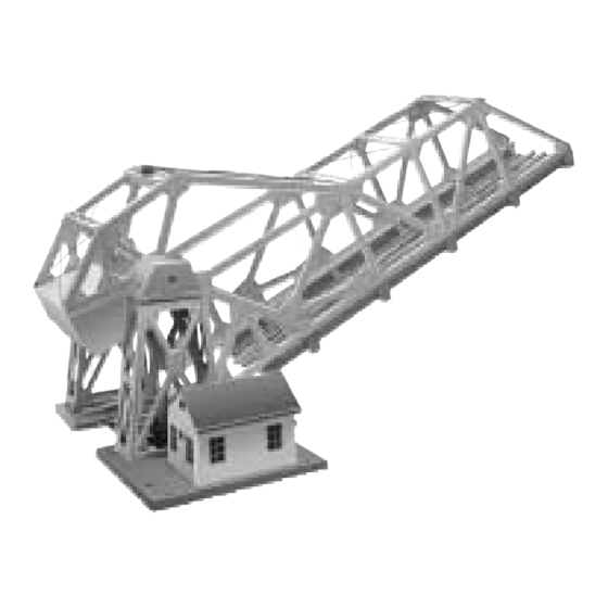
Lionel 313 BASCULE BRIDGE
Operation of your bascule bridge
W
hen properly installed on your layout, activation of the bridge
causes the span to raise to approximately 45°. At the same time,
power to the insulated block leading in and out of the bridge is
removed automatically, to prevent trains from crossing the bridge
while in operation. A second activation lowers the bridge span and
reconnects the power to the insulated block allowing trains to proceed
safely across the bridge. In conventional layouts, the reversing unit
must be locked in forward for automatic train restart. In command
mode, it is necessary to restart your train using your Cab-1 remote. The
bulb inside the shed will light whenever power is on to the bridge. The
flashing warning light atop the bridge will operate only while the
Important notes on installation of your bascule bridge
For Point to Point layouts, track power will need to
be connected to both sides of the bridge, due to the
Note!
insulated section
Installation of your bascule bridge "O" gauge
F
or optimum bridge operation, its location on your layout should
be flat and level. Your bridge is assembled ready for
"O" gauge installation. It displaces two pieces of "O"
gauge straight track. To create the insulated block,
Four track block section
Use appropriate
Use three steel pins pro-
insulating pin for
vided to assemble track to
center rail
bridge
C
ongratulations on your purchase of the Lionel 313 bascule bridge. This classic Lionel
accessory has all the terrific action—and traditional quality—of the 1940-50 original. The
illuminated bascule bridge is made of die-cast metal and stamped steel construction and fea-
tures a powerful DC motor for years of reliable operation.
The bascule bridge can be placed in any Lionel O or O-27 three-rail layout, using the frame
provided and is designed to operate at 12-18 volts alternating current.
bridge is moving or in the raised position. If the bridge is activated
while a train is on the span, a clutch mechanism is included to prevent
damage to the gearbox. The clutch mechanism consists of interlocking
"crowns" which are spring loaded. These will slip over each other in
event of an overload on the bridge.
Note!
Note!
1
Leave
between track and bridge
rails to prevent binding
Orient track pins in
this direction.
Moving section of
bridge rests on pins
U channel track alignment guide
you will need to remove two center rail steel pins at the locations shown
below. There is a large "U" channel/bracket supplied to hold and
align the track at the base of the span(see Page 2 for installation).
Orient track pins in this direction.
Moving section of bridge rests on pins
The noise the clutch mechanism produces as it slips is loud,
do not be alarmed. No damage has occurred.
DO NOT deliberately activate the clutch. Overuse can lead to
premature wear of the mechanism.
/
clearance
16
Four track block section
Use appropriate insulating pin for
center rail
71-2948-250
05/98
Turn cam to lock
down track
Advertisement

Related Manuals for Lionel 313


Summary of Contents for Lionel 313
- Page 1 DC motor for years of reliable operation. The bascule bridge can be placed in any Lionel O or O-27 three-rail layout, using the frame provided and is designed to operate at 12-18 volts alternating current.
- Page 2 (sold separately). Variable voltage control is recom- push the botton and enjoy being the bridge-master mended so you can adjust the bridge speed of operation to your liking. We recommend the Lionel 3 amp To switch: 190-001 included, or a insulated Note! controller part no.
- Page 3 Wiring your bascule bridge to an SC-1 been made, plug your SC-1’s wall pack into a standard outlet. To oper- onnect two insulated wires (included) from the SC-1 to the spring ate your bascule bridge using the SC-1, you must first assign it an acces- clips on the bascule bridge as shown in the diagram below.
- Page 4 Website @ www.Lionel.com his Lionel product including all mechanical and electrical compo- If you prefer to send it back to Lionel L.L.C. for factory repair, you must nents, moving parts, motors and structural components, except for first call 810-949-4100 or FAX 810-949-5429 or write to Customer Service, light bulbs, is warranted to the original consumer-purchaser, for his or her P.O.
Need help?
Do you have a question about the 313 and is the answer not in the manual?
Questions and answers