Table of Contents
Advertisement
Quick Links
Advertisement
Table of Contents

Subscribe to Our Youtube Channel
Related Manuals for Hameg HM 203


Summary of Contents for Hameg HM 203
- Page 1 MANUAL Oscilloscope HM 2 0 3 M E S S T E C H N IK...
-
Page 2: Accessories (Optional)
Test frequency: ferent angles. Particularly for maintenance purposes, the Test connection: 2 banana jacks 4mm dia. One test lead is grounded (Safety Earth). HM 203-4 also has a built-in for quick Component Tester tests and other components, single or in-circuit. -
Page 3: Technical Details
Timebase and Triggering A square-wave generator for probe compensation and a The timebase of the HM 203 operates with a new type of trace rotation device are incorporated. trigger technique developed by HAMEG. Here, the entire... - Page 4 ACCESSORIES HZ 34 Test Cable BIMC-BNC HZ30 100M H z Oscilloscope Probe 10:1 Coaxial test cable with BNC male plugs at each end. Bandwidth DC-100MHz, Risetime 3.5ns. Maximum Cable length 1.2m. Cable capacitance 126pF. input voltage 600V (DC + peak AC). Input impedance Characteristic impedance 50£X Maximum input voltage 10MQ.
-
Page 5: General Information
General Information amounts to ± 3 % in both deflection directions. All values The new HM203-4 is as easy to use as all HAMEG in to be measured can therefore be determined reatively ac struments. Technologically it represents the latest state curately. -
Page 6: Operating Conditions
— after excessive transportation stress (e.g. in poor packaging). mains/line outlet and power plug of the HM 203. Without an isolating transformer, the instrument's power cable must be plugged into an approved three-contact elec... -
Page 7: Probe Adjustment
In spite of Mumetal-shielding of the CRT, effects of the tains the power fuse, which is interchangeable for the dif earth's magnetic field on the horizontal trace position ferent mains/line voltages. The fuse holder with its cannot be completely avoided. This is dependent upon square top plate can be pulled out, and changing of the the orientation o f the oscilloscope on the place of mains/line voltage is possible by turning this plate 90... -
Page 8: Amplitude Measurements
compensated to match the input impedance of the ver not contain any suitable level components and repetition tical amplifier. This can be easily achieved as the HM203 frequency which can be used for triggering. This occurs, has a built-in square-wave generator with a repetition fre for example, with burst signals. -
Page 9: Time Measurements
observed display height H = 4.6cm, required voltage U = 0.05 • 4.6 = 0.23Vpp. Input voltage U = 5Vpp, set deflection coefficient D = 1 V/cm, required display height H = 5:1 = 5cm. Signal voltage U = 220Vrms- 2 • j/2 = 622 Vpp (voltage >... - Page 10 periods or even part of a period may be shown as a func required wavelength L = 1 : (1 5 625 • 10 5) = 6.4cm. tion of the adjustment of the TIMEBASE switch. The time Sine wavelength L = min. 4cm, max. 10cm, coefficients on the TIMEBASE switch are indicated in ms/cm and pslcm.
-
Page 11: Connection Of Test Signal
When using a 50Q eliminated. cable, such as the HZ34, a 50Q through-termination type HZ22 is available from HAMEG. When investigating location and quantitative measurement of a magnetic leakage (e.g. -
Page 12: Triggering And Timebase
sensitivity ranges and input impedances are identical for earthed conductors of other line powered devices, which are connected to the oscilloscope or test object, e.g. both the X and Y axes. However, the Y-POS. II control is signal generators with anti-interference capacitors). disconnected in this mode. - Page 13 Triggering can be selected on either the rising or falling If the video signal of a television set is to be displayed at frame frequency, triggering is generally difficult due to edge of the trigger signal depending on whether the + / —...
-
Page 14: Component Tester
cable connectors. However, this is valid only for the test The time coefficient settings on the TIMEBASE switch of single components (see below: In-Circuit Tests). In the are calibrated when the variable control (small knob on CT mode, the only controls which can be operated are the TIMEBASE switch) is set in the C position. - Page 15 Z-breakdown voltage of more than 12V can not be or a relatively small capacitance or a relatively high in displayed. ductance resp. An ellipse in upright position indicates a small im pedance or a relatively high capacitance or a relatively small inductance resp.
-
Page 16: In-Circuit Tests
Remove all measuring cables inclusive probes between oscilloscope and circuit under test. Each HAMEG oscilloscope is supplied with an Instruction Otherwise the connection o f both CT test leads is not Manual only. However, a wide range of accessories, optional. -
Page 17: Single Components
Single Components Single Transistors Junction B-E Mains transformer prim. Capacitor 33^/F Junction E-C Single Diodes In-circuit Semiconductors Z-diode under 8 V Z-diode beyond 12V Diode paralleled by 6 8 0 fi 2 Diodes antiparallel Germanium diode Diode in series with 5 1 Q B E paraded by 6 8 0 Q Rectifier Thyristor G + A together... -
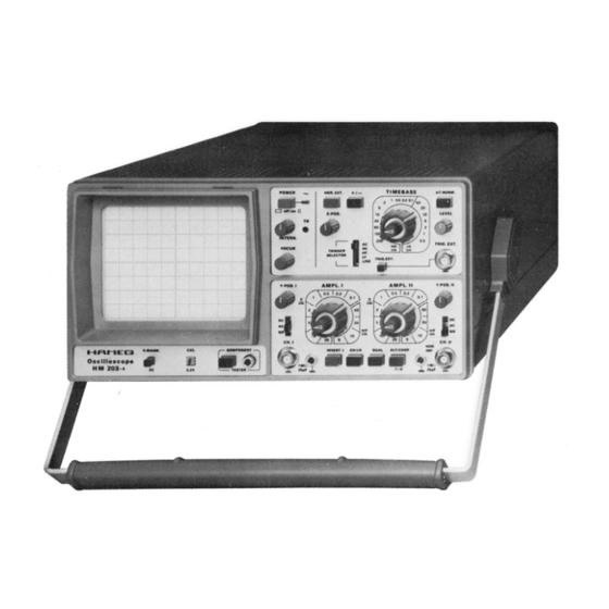
Page 18: Front View
FRONT VIEW... -
Page 19: Trigger Modes
SHORT INSTRUCTION FOR HM 2 0 3 -4 First Time Operation Connect the instrument to power outlet. Switch on POWER pushbutton. No other button is pressed. LED indicates operating condition Case, chassis, and all measuring connectors are connected to the Safety Earth conductor (Safety Class I). TRIGGER SELECTOR switch to AC, AT/NORM. -
Page 20: Test Instructions
(see CRT data book). These limit values are strictly super different characteristics of the dual FETs in both channel vised by HAMEG. The selection of a cathode-ray tube inputs to the Y amplifier. To some extent, fluctuations in without any tolerances is practically impossible. -
Page 21: Calibration Of The Vertical Amplifier
drift are caused by offset current on the gate. The drift is frequency-compensated in each position. Even small capacitive changes can reduce the transmission perfor too high, if the vertical trace position drifts by more than 0.5mm on turning the appropriate attenuator switch mance. -
Page 22: Triggering Checks
quency requires AC (possibly DC) trigger coupling. If no tion of the trace can be adjusted by using both the Chan video signal is available, the function of the LF position nel I and Channel II Y-POS. controls. (low-pass filter) can be checked using mains/line fre quency or the built-in calibrator signal. -
Page 23: Trace Alignment
HM203 is given as + 3 % , but as a rule it is considerably Trace Alignment better than this. For the simultaneous checking of The CRT has an admissible angular deviation ± 5 ° be timebase linearity and accuracy at least 10 oscillations, i.e. -
Page 24: Instrument Case Removal
(M4x30mm) with two washers on it electronic technician, who is carrying out readjustments on the HM 203-4, if the nominal values do not meet the have been removed and after unplugging of the power cord's triple-contact connector. While the instrument specifications. - Page 25 has to be repeatedly turned to and fro until the shape of Operating Voltages the luminous spot, whether round or oval or rectangular, stays the same to the right and left of the optimum focus Besides the two AC voltages for the CRT heating (6.3V) ing.
- Page 26 Replacement parts can be ordered by letter or telephone from the nearest HAMEG Service Of If the instrument fails completely, the first and most fice. Please supply the following information: Instrument important step —...
- Page 27 c onnection of the safety - earth pin via long sold, tab to rear chassis Appliance Inlet — • Safety Class I Plug with earthing contact ♦ °> X X X £ ra > > > > > in o —...
- Page 28 BASIC BLOCK DIAGRAM OF THE HM 20 3-4 The number in the block indicates the relevant circuit diagram.
- Page 29 INDENTIFICATION OF ELECTRICAL COMPONENTS HM 203-4 Electrical components on certain parts of the HM 203-4 Abbreviations Meaning of Connection Abbreviations AI... Appliance inlet are marked such that the first numeral is on: BFt... Bridge rectifier (Silicium) P2-3/1-5 or W2-3/1-5 respectively.
- Page 30 Y-IIMPUI AIMU A [ I EIMUATUR U H .I AIMÜ U H . II MM 2 U 3 -4 C H II...
- Page 31 »12V »5V E Y 21 EY22 -12V...
- Page 32 Y-IIMTERMEDIATE AMPL. CH.I + II, CHANNEL FLIP-FLOP, CHOPPER GENERATOR, GATES, TRIG. AND X-SIGNAL AMPL., TRIG. SIGNAL FINAL AMPL., COMPONENT TESTER HM 203-4 © ) W2-5/1- 140V to Z-Board - < T ) W2-5/1- ♦3.7SV from Z-Board R512 ♦24V to Z-Board...
- Page 33 COMPONENT LOCATIONS XY-BOARD HM 203-4 W0-2/J- fro« T» 001 R 2 1 2 R272 R 210 R 2 2 0 V R 220 R 201 R 256 R264 R 200 R 235 R 2 07 6 R 230 R 240...
- Page 34 TRIGGER CIRCUIT, TIMEBASE CIRCUIT, X-FINAL AMPLIFIER, LV-POWER 12VT, TRACE ROTATION HM 20 3-4 TRIG. EXT TRIG. EXT. from LV Power BR2071 W 2-6/1- - © LED 001 d p p rc x . 1 C C J1 X-MAGN. X5 1C0C turns...
- Page 35 COMPONENT LOCATIONS T-BOARD HM 203-4 W 0 -3 /4- to LOOI trace rotation R 3 2 2 R 3 8 3 R 3 1 9 R 3 4 0 R 3 5 6 R 3 1 4 R 3 0 0 R 3 5 2...
- Page 36 UNBLANKING CIRCUIT, CRT CIRCUIT HM 203-4 R3117...
- Page 37 Y-FINAL AMPLIFIER HM 203-4 Z-Board WO-5/1- from Power Tran sfo rm er 1?V *- W 5 - 6 /V to CRT Y1 (DC) W 5 -6 /2 - to CRT Y2 (03) W 5 -6 /3 - to CRT 140V...
- Page 38 LV + HV POWER SUPPLY HM 2 0 3 -4 T-Board HV-Power WO-3/6- -1878V POWER TRANSFORMER TR 001 031/0018 POWER AC 50.. 60Hz POWER FUSE LINKS Type: IEC 127-111 DIN 41662 SEV 1064 BS 4265 5 x20 mm, time lag 110V } T 0.63 A 125V...
- Page 39 COMPONENT LOCATIONS, CALIBRATOR HM 203-4 Preamplifier CH. II Preamplifier CH. I CRT-Board CRT-Board TS-Board wiring side Calibrator R2005 ■ o ► 5V IC2001 C2004 4 x1 /1 . HEF4011BP -01— I 10p 35V R2003 □D C2001 VR2001 _ L T \...
- Page 40 Adjust the forward current of the optocoupler diode in the middle of the following points: a) bright spot on left side of the trace (screen of the HM 203-4), b) shortening on right side of the trace (screen of the HM 203-4).
- Page 41 XY-Board {Component side) VR 2011 Astigmatism VR2071 correction + 1 40V adj. (ChP6) VR2021 Current adj. X-Final ampl. (X-Pos. control centered) (ChP4 +3.1 V antipole C h P I) VR 212 Adj. with 20m Vpp ---------------------------- 1... 5kHz in Y-Gain 5m V/cm (DC) position Ch.ll VR 222...
-
Page 42: Trigger Board
Trigger Board (Component side) CRT Cathode Check n j 2 2 V + ( - 1 9 0 0 V ) ^ “ strip - 1 9 0 0 V ^ • • -------------1 + 3.75 V • V R 31 0 2 VR3101 ©... - Page 43 Q — O E O U ^ T I E ES West Germany G .m .b.H. Kelsterbacher Str. 15-19 - 6 FRANKFURT/M. 71 Tel.(0611)676017-19 Telex 0413866 D-d /FÜ D^I] [E [E3 France S.A.R.L. 5-9, avenue de la R6publique — 94800 VILLEJUIF T6I.
Need help?
Do you have a question about the HM 203 and is the answer not in the manual?
Questions and answers