Table of Contents
Advertisement
Quick Links
C
OM-01863-OB02
November 7, 1986
Rev.D
INSTALLATION, OPERATION,
AND MAINTENANCE MANUAL
WITH PARTS LIST
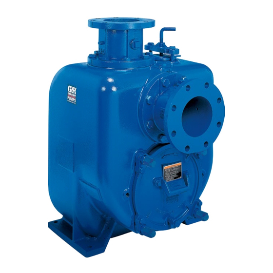
U SERIES PUMP
MODEL
U4B60---B
INCLUDING: /F, /FM
THE GORMAN-RUPP COMPANY D MANSFIELD, OHIO
GORMAN-RUPP OF CANADA LIMITED
ST. THOMAS, ONTARIO, CANADA
D
Printed in U.S.A.
E
Copyright by the Gorman-Rupp Company
Advertisement
Table of Contents

Related Manuals for GORMAN-RUPP U4B60-B


Summary of Contents for GORMAN-RUPP U4B60-B
- Page 1 November 7, 1986 Rev.D INSTALLATION, OPERATION, AND MAINTENANCE MANUAL WITH PARTS LIST U SERIES PUMP MODEL U4B60---B INCLUDING: /F, /FM THE GORMAN-RUPP COMPANY D MANSFIELD, OHIO GORMAN-RUPP OF CANADA LIMITED ST. THOMAS, ONTARIO, CANADA Printed in U.S.A. Copyright by the Gorman-Rupp Company...
- Page 2 TABLE OF CONTENTS INTRODUCTION ..........PAGE I --- 1 SAFETY --- SECTION A .
-
Page 3: Table Of Contents
TABLE OF CONTENTS (continued) TROUBLESHOOTING --- SECTION D ......PAGE D --- 1 PREVENTIVE MAINTENANCE . - Page 4 If there are any questions regarding the pump or its application which are not covered in this manual or in other literature accompanying this unit, please contact your Gorman-Rupp distributor, or write: The Gorman-Rupp Company Gorman-Rupp of Canada Limited P .O.
- Page 5 OM -- 01863-- 02 SAFETY --- SECTION A This information applies to U Series ba- sic pumps. Gorman-Rupp has no con- trol over or particular knowledge of the power source which will be used. Refer After the pump has been positioned,...
- Page 6 OM -- 01863-- 02 U SERIES Never run this pump backwards. Be cer- Use lifting and moving equipment in tain that rotation is correct before fully good repair and with adequate capacity engaging the pump. to prevent injuries to personnel or dam- age to equipment.
- Page 7 For further assistance, contact your Gorman-Rupp Most of the information pertains to a standard distributor or the Gorman-Rupp Company. static lift application where the pump is posi- tioned above the free level of liquid to be pumped.
- Page 8 If the maximum shelf life has been exceeded, or if anything appears to be abnormal, contact your Gorman-Rupp distributor or the factory to deter- Pump performance is adversely effected by in- mine the repair or updating policy. Do not put the...
- Page 9 U SERIES OM -- 01863-- 02 SUCTION LINES overall application allows pump to operate within the safe operation range. To avoid air pockets which could affect pump prim- ing, the suction line must be as short and direct as possible. When operation involves a suction lift, the Materials line must always slope upward to the pump from the source of the liquid being pumped;...
- Page 10 OM -- 01863-- 02 U SERIES Suction Lines In Sumps of one or both pumps. To avoid this, position the suction inlets so that they are separated by a dis- If a single suction line is installed in a sump, it tance equal to at least 3 times the diameter of the should be positioned away from the wall of the suction pipe.
- Page 11 Therefore, it is recom- If the application involves a high discharge mended that a Gorman-Rupp Automatic Air Re- head, gradually close the discharge lease Valve be installed in the bypass line.
- Page 12 Some leakage (1 to 5 gallons [4 to 19 li- the specific hydraulic operating conditions of the ters] per minute) will occur when the application, the Gorman-Rupp Automatic Air Re- lease Valve will permit air to escape through the by- valve is fully closed. Be sure the bypass...
- Page 13 Contact your Gorman-Rupp distributor or the Gor- man-Rupp Company for information about installa- well or sump. The bleed line must be the same size as the inlet piping, or larger.
- Page 14 Check Rotation, Section C, before final alignment of the pump. Figure 6A. Aligning Spider-Type Couplings When mounted at the Gorman-Rupp factory, driver and pump are aligned before shipment. Misalign- ment will occur in transit and handling. Pumps must be checked and realigned before operation.
- Page 15 U SERIES OM -- 01863-- 02 V-Belt Drives When using V-belt drives, the power source and the pump must be parallel. Use a straightedge along the sides of the pulleys to ensure that the pul- Do not operate the pump without the leys are properly aligned (see Figure 6C).
- Page 16 OM -- 01863-- 02 U SERIES OPERATION --- SECTION C not prime when dry. extended operation of Review all SAFETY information in Section A. a dry pump will destroy the seal assembly. Follow the instructions on all tags, labels and de- Add liquid to the pump casing when: cals attached to the pump.
- Page 17 Lines With a Bypass line connections and fittings tight to maintain maxi- mum pump efficiency. If a Gorman-Rupp Automatic Air Release Valve has been installed, the valve will automatically open to allow the pump to prime, and automatically close Liquid Temperature And Overheating after priming is complete (see INSTALLATION for Air Release Valve operation).
- Page 18 On engine driven pumps, reduce the throttle valve with a substitute which has not been speci- speed slowly and allow the engine to idle briefly be- fied or provided by the Gorman-Rupp Company. fore stopping. Strainer Check If the application involves a high discharge...
- Page 19 OM -- 01863-- 02 U SERIES liquid during the draining process. Clean out any against the housing. Record this temperature for remaining solids by flushing with a hose. future reference. A sudden increase in bearing temperature is a warning that the bearings are at the point of failing BEARING TEMPERATURE CHECK to operate properly.
-
Page 20: Troubleshooting
U SERIES OM -- 01863-- 02 TROUBLESHOOTING --- SECTION D Review all SAFETY information in Section A. Before attempting to open or service the pump: 1. Familiarize yourself with this manual. 2. Lock out or disconnect the power source to ensure that the pump will remain inoperative. - Page 21 OM -- 01863-- 02 U SERIES TROUBLE POSSIBLE CAUSE PROBABLE REMEDY Air leak in suction line. Correct leak. PUMP STOPS OR FAILS TO DELIVER Lining of suction hose collapsed. Replace suction hose. RATED FLOW OR PRESSURE Leaking or worn seal or pump gasket. Check pump vacuum.
-
Page 22: Preventive Maintenance
Gorman-Rupp pump. For specific questions con- For new applications, a first inspection of wearing cerning your application, contact your Gorman- parts at 250 hours will give insight into the wear rate Rupp distributor or the Gorman-Rupp Company. - Page 23 OM -- 01863-- 02 U SERIES Preventive Maintenance Schedule Service Interval* Item Daily Weekly Monthly Semi- Annually Annually General Condition (Temperature, Unusual Noises or Vibrations, Cracks, Leaks, Loose Hardware, Etc.) Pump Performance (Gauges, Speed, Flow) Bearing Lubrication Seal Lubrication (And Packing Adjustment, If So Equipped) V-Belts (If So Equipped) Air Release Valve Plunger Rod (If So Equipped)
-
Page 24: Pump Maintenance And Repair
MAINTENANCE AND REPAIR OF THE WEARING PARTS OF THE PUMP WILL MAINTAIN PEAK OPER- ATING PERFORMANCE. STANDARD PERFORMANCE FOR PUMP MODEL U4B60-B Based on 70_ F (21_ C) clear water at sea level Contact the Gorman-Rupp Company to verify per- formance or part numbers. - Page 25 OM -- 01863-- 02 U SERIES SECTION DRAWING TOP VIEW 7, 8 Figure 1. Pump Model U4B60---B PAGE E -- 2 MAINTENANCE & REPAIR...
-
Page 26: Parts Lists
PARTS LIST Pump Model U4B60---B (From S/N 860554 up) If your pump serial number is followed by an “N”, your pump is NOT a standard production model. Contact the Gorman-Rupp Company to verify part numbers. ITEM PART NAME PART MAT’L... - Page 27 OM -- 01863-- 02 U SERIES SECTION DRAWING DRIVE END VIEW SEAL AREA DETAIL Figure 2. 44163---041 Repair Rotating Assembly PAGE E -- 4 MAINTENANCE & REPAIR...
- Page 28 OM -- 01863-- 02 U SERIES PARTS LIST 44163---041 Repair Rotating Assembly ITEM PART MAT’L PART NAME NUMBER CODE IMPELLER 38619---011 11000 SEAL PLATE O-RING 25152---276 --- --- --- SEAL ASSEMBLY 46513---151 --- --- --- INBOARD BALL BEARING 23276---009 --- --- --- BEARING HOUSING 38251---508 10010...
-
Page 29: Pump And Seal Disassembly And Reassembly
OM -- 01863-- 02 U SERIES PUMP AND SEAL DISASSEMBLY 6. Vent the pump slowly and cau- AND REASSEMBLY tiously. 7. Drain the pump. Review all SAFETY information in Section A. Follow the instructions on all tags, label and decals attached to the pump. -
Page 30: Impeller Removal
U SERIES OM -- 01863-- 02 (Figure 1) however, the power source must be removed to provide clearance. Remove the hardware (15 and 16) securing the ro- tating assembly to the pump casing. Separate the The impeller (1) should be loosened while the rotat- rotating assembly by pulling straight away from the ing assembly is still secured to the pump casing. -
Page 31: Seal Removal
OM -- 01863-- 02 U SERIES sion on the shaft seal spring will be released as the Disengage the hardware (15 and16) and slide the impeller is removed. Inspect the impeller and re- bearing cap (10) and oil seal (13) off the shaft.Re- place if cracked or badly worn. -
Page 32: Shaft And Bearing Reassembly And Installation
U SERIES OM -- 01863-- 02 be replaced any time the shaft and bear- tation is rough or the bearing balls are discolored, replace the bearings. ings are removed. The bearing tolerances provide a tight press fit NOTE onto the shaft and a snug slip fit into the bearing Position the inboard bearing (4) on the shaft with housing. -
Page 33: Seal Installation
OM -- 01863-- 02 U SERIES Most cleaning solvents are toxic and Slide the shaft and assembled bearings into the bearing housing until the retaining ring on the out- flammable. Use them only in a well --- board bearing seats against the bearing housing. ventilated area free from excessive heat, sparks, and flame. - Page 34 U SERIES OM -- 01863-- 02 RETAINER SEAL PLATE SPRING O-RINGS IMPELLER SLEEVE O-RING IMPELLER SHIMS IMPEL- INTEGRAL SHAFT SHAFT ROTAT- STATION- SLEEVE BELLOWS ING ELE- ARY ELE- MENT MENT SHEAR SPRING RING (SHEARED) CENTER- ING WASH- STATION- DRIVE BAND ARY SEAT Figure 5.
- Page 35 OM -- 01863-- 02 U SERIES and screw the impeller onto the shaft until it is Measure the impeller-to-seal plate clearance, and seated against the seal (see Figure 6). remove impeller adjusting shims to obtain the proper clearance as described in Impeller Instal- O-RING ENGAGED lation and Adjustment.
-
Page 36: Impeller Installation
U SERIES OM -- 01863-- 02 pump casing, this clearance may be measured by the pipe should be slightly larger than the O.D. of the shaft sleeve. reaching through the priming port with a feeler gauge. Slide the rotating portion of the seal (consisting of the integral shaft sleeve, spring centering washer, spring, bellows and retainer, and rotating element) NOTE... -
Page 37: Suction Check Valve Installation
‘Permatex replace this valve with a substitute which has not Aviation No. 3 Form-A-Gasket’ or equivalent com- been specified or provided by the Gorman-Rupp pound to the mating surfaces, and secure them to Company. PAGE E -- 14... -
Page 38: Final Pump Assembly
U SERIES OM -- 01863-- 02 Periodically, the valve should be removed for in- Clean and reinstall the vented plug. Maintain the oil spection and cleaning. When reinstalling the relief at this level. valve, apply ‘Loctite Pipe Sealant With Teflon No. 592’, or equivalent compound, on the relief valve Bearings threads. - Page 39 For U.S. and International Warranty Information, Please Visit www.grpumps.com/warranty or call: U.S.: 419−755−1280 International: +1−419−755−1352 For Canadian Warranty Information, Please Visit www.grcanada.com/warranty or call: 519−631−2870 THE GORMAN-RUPP COMPANY D MANSFIELD, OHIO GORMAN-RUPP OF CANADA LIMITED ST. THOMAS, ONTARIO, CANADA...
Need help?
Do you have a question about the U4B60-B and is the answer not in the manual?
Questions and answers