Table of Contents
Advertisement
Quick Links
Advertisement
Table of Contents
Troubleshooting

Related Manuals for Samsung AC TNPPEH Series


Summary of Contents for Samsung AC TNPPEH Series
- Page 1 Air conditioner User & installation manual AC***TNPPEH • Thank you for purchasing this Samsung air conditioner. • Before operating this unit, please read this manual carefully and retain it for future reference. DB68-09343A-00 DB68-09343A-00_IBIM_PAC 미라지 이집트파키스탄_IQ_EN.indd 1 2020-07-28 오전 11:08:42...
-
Page 2: Table Of Contents
Contents Safety Information Safety Information (Using the Air Conditioner) Operation Features Checking auxiliary power switch • Operating temperature and humidity At a Glance Indoor Unit Overview Opening the panel Control Panel Overview Indoor unit display Controlling with the control panel Turning on or off the air conditioner •... - Page 3 Safety Information Safety Information (Installing the Air Conditioner) General information Installing the unit Power supply line, fuse or circuit breaker Installation Procedure Installation Procedure Step 1 Choosing the installation location Step 2 Checking and preparing accessories Step 3 Drilling a hole through a wall Step 4 Taping the pipes, cables, and drain hose Step 5 Purging inert gas from the indoor unit Step 6 Optional: Cutting and flaring the pipes...
-
Page 4: Safety Information
If you have any questions, call your nearest contact center or find help and information online at www.samsung.com. These warning signs are here to prevent injury to you and others. Please follow them carefully. - Page 5 FOR INSTALLATION WARNING Use the power line with the power specifications of the product or higher and use the power line for this appliance only. In addition, do not use an extension line. • Extending the power line may result in electric shock or fire. •...
- Page 6 Safety Information (Using the Air Conditioner) This appliance must be properly grounded. Do not ground the appliance to a gas pipe, plastic water pipe, or telephone line. • Failure to do so may result in electric shock, fire, an explosion, or other problems with the product.
- Page 7 FOR POWER SUPPLY WARNING When the circuit breaker is damaged, contact your nearest service centre. Do not pull or excessively bend the power line. Do not twist or tie the power line. Do not hook the power line over a metal object, place a heavy object on the power line, insert the power line between objects, or push the power line into the space behind the appliance.
- Page 8 Safety Information (Using the Air Conditioner) To reinstall the air conditioner, please contact your nearest service centre. • Failing to do so may result in problems with the product, water leakage, electric shock, or fire. • A delivery service for the product is not provided. If you reinstall the product in another location, additional construction expenses and an installation fee will be charged.
- Page 9 Do not insert your fingers or foreign substances into the air inlet/outlet of the air conditioner. • Take special care that children do not injure themselves by inserting their fingers into the product. Do not use this air conditioner for long periods of time in badly ventilated locations or near infirm people.
- Page 10 Safety Information (Using the Air Conditioner) Do not stand on top of the appliance or place objects (such as laundry, lighted candles, lighted cigarettes, dishes, chemicals, metal objects, etc.) on the appliance. • This may result in electric shock, fire, problems with the product, or injury. Do not operate the appliance with wet hands.
- Page 11 FOR CLEANING WARNING Do not clean the appliance by spraying water directly onto it. Do not use benzene, thinner, alcohol or acetone to clean the appliance. • This may result in discoloration, deformation, damage, electric shock or fire. Before cleaning or performing maintenance, unplug the air conditioner from the wall socket and wait until the fan stops.
-
Page 12: Operation Features
Operation Features Checking auxiliary power switch Turn on the auxiliary power switch which is 1 phase circuit breaker 3 phase 4 wire circuit breaker installed separately. NOTE Auxiliary power switch(ELCB, ELB) • Auxiliary power switch is not included in the package. Purchase and install it separately. •... -
Page 13: At A Glance
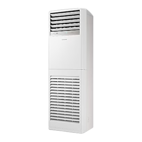
Indoor Unit Overview The actual product may differ slightly from the image depicted below. 01 Air flow blade (up and down) 02 Air flow blade (left and right) 03 Air outlet 04 Control panel 05 Indoor unit display 06 Air filter 07 Remote control holder 08 Air intake 09 Safety hook... -
Page 14: Control Panel Overview
Control Panel Overview 01 Power button 04 Indoor unit display 05 Temperature button 02 Mode button (Lock button) 03 Fan speed button (Turbo function Button) Indoor unit display 02 03 04 01 Operation mode indicators 05 Fan speed indicator 02 Defrost operation indicator 06 Set temperature indicator 03 Outdoor unit operation indicator 07 Turbo function indicator /... -
Page 15: Controlling With The Control Panel
Controlling with the control panel You can control the air conditioner with the control panel without using the remote control. Turning on or off the air conditioner Press the (Power) button. The air conditioner turns on with a ring sound and then its operation starts. -
Page 16: Selecting The Operation Mode/Locking The Control Panel
Controlling with the control panel Selecting the operation mode/ Locking the control panel • Press the (Mode) button to change the operation mode. Each time you press the button, the mode changes in the following order: Auto → (Lock 3sec) Cool →... -
Page 17: Remote Control Overview
Remote Control Overview 01 Set temperature indicator 02 Timed on/off indicator 03 Operation mode indicator 04 Unsupported functions NOTE • The Single user, Heater and Purity functions ( are not supported by this model. 05 Low battery indicator 06 Signal transmission indicator 07 Fan speed indicator 08 Vertical air swing indicator / Horizontal air swing indicator... -
Page 18: Replacing Batteries • Storing The Remote Control
Remote Control Overview Replacing batteries When the icon appears in the remote control display, replace the batteries with new ones. Two 1.5V AAA type batteries are required. Two 1.5V AAA type batteries Correct disposal of batteries in this product This marking on the battery, manual or packaging indicates that the batteries in this product should not be disposed of with other household waste at the end of their working life. -
Page 19: Remote Control Operation
Remote Control Operation You can use the air conditioner easily by selecting a mode or function and then by controlling the temperature, fan speed, and air flow direction. Turning on or off the air conditioner You can turn on or off the air conditioner by pressing the (Power) button. -
Page 20: Controlling Fan Speed • Controlling Temperature • Controlling Air Flow Direction
Remote Control Operation Controlling fan speed You can select the following fan speeds in each mode: Mode Available fan speeds Auto/Dry (Auto) Cool/Heat (Auto), (Med), (High), (Turbo) (Med), (High), (Turbo) Controlling temperature You can control the temperature in each mode as follows: Mode Temperature control Auto/Cool/Dry Adjust by 1°C between 18°C and 30°C. -
Page 21: Power Smart Features
Power Smart Features Auto mode Use the Auto mode when you want the air conditioner to automatically control the mode (Heat or Cool). The air conditioner will provide the most comfortable atmosphere that it can. ▶ ▶ Select Auto. NOTE •... -
Page 22: Dry Mode • Fan Mode
Power Smart Features Dry mode Use the Dry mode in rainy or humid weather. ▶ ▶ Select Dry. NOTE • You cannot change fan speed in the Dry mode. • The greater the difference between the set temperature and the current temperature is, the greater the amount of air that is dehumidified is. -
Page 23: Heat Mode
Heat mode Use the Heat mode to stay warm. ▶ ▶ Select Heat. NOTE • While the air conditioner warms up, the fan may not operate for a while at the beginning to prevent cold wind. • While the defrost function is running, the indoor unit provides no breeze to prevent cold wind. -
Page 24: Variety Smart Features
Variety Smart Features Turbo function Use the Turbo function to quickly cool your room. This function provides the most powerful cooling air. ▶ NOTE • To turn off the Turbo function, press (Turbo) button again. • This function is only available in the Auto and Cool modes. •... -
Page 25: Clean Function
Clean function Use the Clean function to remove moisture from the inside of the air conditioner for preventing propagation of fungi, bacteria, etc. ▶ ▶ Select Clean. ▶ • When the Clean function is set, the (Clean) indicator appears on the indoor unit display. When the air conditioner is ended, the Clean function starts for 10 minutes and then the air conditioner turns off. -
Page 26: Energy-Saving Operation
Energy-Saving Operation Timed on/Timed off function Use the Timed on/off function to turn the air conditioner on or off after the time that you set. ▶ ▶ Select On or Off. ▶ (Set the on/off time.) ▶ NOTE • You can set a time between 0.5 and 24 hours. •... -
Page 27: Cleaning And Maintenance
Cleaning at a Glance Cleaning the indoor unit exterior and outdoor unit heat exterior Tepid damp cloth Soft brush Before cleaning, be sure to Spray water to clean the dust. turn off the air conditioner. CAUTION • Do not open the panel when the air conditioner is operating. This action may cause a malfunction or an electrical hazard. - Page 28 Cleaning at a Glance Cleaning the filter Vacuum cleaner CAUTION • Do not scrub the air filter with a brush or other cleaning utensil. This may damage the filter. • Do not expose the air filter to direct sunlight when drying it. NOTE •...
- Page 29 Periodical maintenance Requires qualified Unit Maintenance item Interval technicians Clean the air filter. Once every 2 weeks Clean the condensate drain pan. Once a year Required Clean up the heat exchange. Once a year Required Indoor unit Clean the condensate drain pipe. Once every 4 months Required Replace the remote control...
-
Page 30: Troubleshooting
Troubleshooting Refer to the following chart if the air conditioner operates abnormally. This may save time and unnecessary expense. Problem Solution • Check if the power plug is properly connected. • Check whether the auxiliary power switch (ELCB, ELB) is turned on. •... - Page 31 Problem Solution The Timed on/off • Check whether you pressed the (SET) button on the remote control function does not after setting the on/off time. Set the on/off time. operate. • Check whether is displayed on the indoor unit display. Make sure that the power and communication cables are connected correctly between the indoor and outdoor units, and then restart the air conditioner.
- Page 32 Troubleshooting Problem Solution • In certain conditions (especially, when the outdoor temperature is lower The air conditioner than 20°C), a hissing, rumbling, or splashing sound may be heard while makes strange the refrigerant is circulating through the air conditioner. This is a normal noises.
-
Page 33: Safety Information (Installing The Air Conditioner)
• This manual explains how to install an indoor unit with • This appliance is not intended for use by persons a split system with two SAMSUNG units. The use of (including children) with reduced physical, sensory other types of units with different control systems may or mental capabilities, or lack of experience and damage the units and invalidate the warranty. -
Page 34: Power Supply Line, Fuse Or Circuit Breaker
Safety Information (Installing the Air Conditioner) • Do not use the air conditioner in environments with • Always make sure that the power supply is compliant with hazardous substances or close to equipment that current safety standards. Always install the air conditioner release free flames to avoid the occurrence of fires, in compliance with current local safety standards. -
Page 35: Installation Procedure
Installation Procedure Step 1 Choosing the installation location Step 2 Checking and preparing accessories Determine the installation location considering the following conditions and obtain the user approval. The following accessories are supplied with the air conditioner. Their type and quantity may differ depending Indoor unit on the specifications. -
Page 36: Step 3 Drilling A Hole Through A Wall
Installation Procedure Step 3 Drilling a hole through a wall Insulation type (heating/cooling) 1 Determine the position of a 60 to 65 mm hole considering Standard High Pipe size possible directions of the pipe bundle and minimum humidity Pipe Remarks (Less than (mm) distances between the hole and installation plate. -
Page 37: Step 5 Purging Inert Gas From The Indoor Unit
Step 6 Optional: Cutting and flaring NOTE the pipes • Be sure to insulate the pipes without gaps or cracks, and use adhesive between the connecting parts of the insulation to prevent moisture from entering. 1 Make sure that you have the required tools available: pipe cutter, reamer, flaring tool, and pipe holder. -
Page 38: Step 7 Connecting The Refrigerant Pipes
Installation Procedure 5 Check that the flaring is correct, referring to the WARNING illustrations below for examples of incorrect flaring. • During installation, make sure that there is no gas leakage. When collecting refrigerant, first stop the compressor. If the refrigerant pipe is not properly connected and compressor runs with the service valve open, the pipe takes in air and the pressure rises, which may cause explosion or injury. -
Page 39: Step 9 Fixing And Insulating The Connection Part For Refrigerant Pipes
Step 9 Fixing and insulating the 2 Fasten the pipes with a pipe clamp and fix it with screws. connection part for refrigerant pipes CAUTION • Before wrapping the connection part for refrigerant pipes, be sure to check whether there is gas leakage on the connection part. -
Page 40: Step 11 Performing Drainage Test
Installation Procedure Step 11 Performing drainage test 2 Insert the end of the drain hose to the extension drain hose to make a connection. 3 Tightly wrap the connection part with a cable tie or tape Put the water bottle deeply into the first blade on the left of the air outlet and slowly pour water. - Page 41 AC036/048TNPPEH (1-phase) (Unit: mm) Communication: M3.5 screw AC power: M4 screw Indoor Unit 1(L) 2(N) Cable clamp Tightening torque (N·m) M3.5 0.8 to 1.2 Outdoor Unit 1.2 to 1.8 • 1 N·m = 10 kgf·cm F1 F2 1(L)2(N) • Power supply cords of parts of appliances for outdoor use shall not be lighter than polychloroprene sheathed flexible Cable tie cord.
-
Page 42: Step 13 Optional: Extending The Power Cable
Installation Procedure Step 13 Optional: Extending the 3 Insert both sides of core wire of the power cable into the connection sleeve. power cable • Method 1: Push the core wire into the sleeve from both sides. 1 Prepare the following tools. •... -
Page 43: Step 14 Setting The Indoor Unit Addresses And The Installation Options
Step 14 Setting the indoor unit 5 Wrap it with the insulation tape twice or more and position your contraction tube in the middle of the addresses and the installation options insulation tape. You cannot set both of the indoor unit addresses and Method 1 Method 2 the installation options in a batch: set both of them... - Page 44 Installation Procedure 2 Set the option values. SEG1 SEG2 SEG3 SEG4 SEG5 SEG6 CAUTION SEG7 SEG8 SEG9 SEG10 SEG11 SEG12 • The total number of available options are 24: SEG1 to SEG24. • Because SEG1, SEG7, SEG13, and SEG19 are the page options used by the previous remote control models, SEG13 SEG14...
- Page 45 Steps Remote control display b Set the SEG5 value by pressing the (High Fan) button repeatedly until the value you want to set appears on the remote control display. When you press the (Low Fan) or (High Fan) button, values appear in the following order: SEG5 4 Press the...
- Page 46 Installation Procedure Steps Remote control display 9 Set the SEG11 and SEG12 values: a Set the SEG11 value by pressing the (Low Fan) button repeatedly until the value you want to set appears on the remote control display. SEG11 b Set the SEG12 value by pressing the (High Fan) button repeatedly until the value you want to set appears on the remote control display.
- Page 47 Steps Remote control display 14 Press the (Mode) button. Dry and Off appear on the remote control display. 15 Set the SEG18 and SEG20 values: a Set the SEG18 value by pressing the (Low Fan) button repeatedly until the value you want to set appears on the remote control display. SEG18 b Set the SEG20 value by pressing the (High Fan) button repeatedly until the...
- Page 48 Installation Procedure Steps Remote control display b Set the SEG24 value by pressing the (High Fan) button repeatedly until the value you want to set appears on the remote control display. When you press the (Low Fan) or (High Fan) button, values appear in the following order: SEG24 3 Check whether the option values that you have set are correct by pressing the...
- Page 49 2 Set an address for each indoor unit using the remote control, according to your air conditioning system plan, by referring to the following table and by following the steps in Common steps for setting the addresses and options on page 43.
- Page 50 Installation Procedure 2 Set the installation options of indoor units, by referring to the following table and by following the steps in Common steps for setting the addresses and options on page 43. • The installation options of indoor units are set to 020000-100000-200000-300000 by default. Option SEG1 SEG2...
- Page 51 Emergency Temperature Output (ETO) function CAUTION • In order to deploy the ETO function, the MIM-B14, an external contact interface module, must be installed in each indoor unit. – The ETO is a concept of emergency operation of indoor units. If the indoor unit 1 (main indoor unit) stops because of an error, the indoor unit 2 (sub indoor unit) starts to operate.
-
Page 52: Step 15 Optional: Fixing The Indoor Unit
Installation Procedure ETO operation specifications 1 Main indoor unit – Based on the external contact control settings, the main indoor unit decides whether to generate output when an error (indoor unit stop) occurs. – Based on the ETO settings, the main indoor unit decides whether to generate output according to the temperature and time conditions. -
Page 53: Appendix
Appendix Troubleshooting Error Code Meaning Remarks Check the communication cable connection between Indoor unit communication error the indoor unit and the outdoor unit. E101 (indoor unit cannot receive communication.) Check the DC output voltage at the communication terminal. E108 Error due to duplicated communication address Check on repeated indoor unit main address Check indoor unit's quantity setting in outdoor unit. - Page 54 Appendix Error Code Meaning Remarks 1. Check the range of temperature limited for heating Heating operation restricted at outdoor temperature operation E440 over Theat_high value (default:30°C) 2. Check the outdoor temperature sensor 1. Check the range of temperature limited for cooling Cooling operation restricted at outdoor temperature operation E441...
- Page 55 Memo English DB68-09343A-00_IBIM_PAC 미라지 이집트파키스탄_IQ_EN.indd 55 2020-07-28 오전 11:08:55...
- Page 56 QUESTIONS OR COMMENTS? COUNTRY CALL OR VISIT US ONLINE AT PAKISTAN 0800-Samsung (72678) www.samsung.com/pk/support Iraq 80010080 www.samsung.com/levant/support DB68-09343A-00_IBIM_PAC 미라지 이집트파키스탄_IQ_EN.indd 56 2020-07-28 오전 11:08:55...