Advertisement
Quick Links
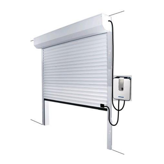
NOVOROL
from
FOAM FILLED ROLLER DOOR WITH SURROUNDING BOX
(NOVOROL NR-20 CONTROL BOX WITH WIRED SAFETY EDGE)
STEP by STEP GUIDE
1 – Check Contents and condition of parts received
2 – Check Brickwork opening, dimensionally and condition
3 – Fit Guides to brickwork – Page 4
4 – Fit Box complete with Shaft – Page 4
5 – Fit Control Box to wall – Page 5
6 – Connect Motor via Test Leads and Mains – Page 5
7 – Run Shaft to BOTTOM Limit – Page 6
8 – Run Shaft to TOP Limit (Count Shaft Revs) – Page 6
9 – Run Shaft to Bottom Limit – Page 7
10 – Put Curtain over Shaft into Guides – Page 7
11– Connect Curtain to Shaft – Page 8
12 – Adjust BOTTOM Limit / Closed Position – Page 9
13 – Run Curtain to TOP – Page 9
14 – Adjust TOP Limit / Open Position – Page 9
15 – On Test Leads, Run Door to Fully Closed – Page 10
16 – ON Test Leads to Run, Run Door to Fully Open – Page 10
17 – Connect Motor and Safety Edge to Control Box – Page 10
18 – RUN Door via Control Box
19 – Program Handsets Page 10
20 – TEST Door (Safety Edge / Handsets) – Page 11
21 – Explain to End User how the door works
( 1 )
Advertisement

Related Manuals for Novoferm NOVOROL NR-20


Summary of Contents for Novoferm NOVOROL NR-20
- Page 1 NOVOROL from FOAM FILLED ROLLER DOOR WITH SURROUNDING BOX (NOVOROL NR-20 CONTROL BOX WITH WIRED SAFETY EDGE) STEP by STEP GUIDE 1 – Check Contents and condition of parts received 2 – Check Brickwork opening, dimensionally and condition 3 – Fit Guides to brickwork – Page 4 4 –...
-
Page 2: General Information
Any damage occurring as a result of non-compliance with these instructions shall exempt the manufacturer from all liability If after reading these instructions there are any questions or anything is not understood then Contact Novoferm Customer Service on 01582 563 777 for guidance ... -
Page 3: Installation Instructions
Terms of Warranty The purchaser is granted a warranty covering the safe and reliable operation of the Novoferm “Novorol” Garage Door for a period of 5 years from the date of purchase. This warranty is conditional on the regular inspection and maintenance of the product in accordance with the installation manual supplied with this door. - Page 4 Tools Required: Drill Bits – Metal to 6 & 12.5mm Dia Drill Bits Masonry to suit fixings Screwdrivers – Pozi 2pt – Electricians Motor Test Leads Level, Ladder x 2, Motor Limit Adjusting Wand (should be with Motor), Hammer, Quick Clamps 600mm reach (4 off) Parts Delivered / Required 2 Cardboard Boxes containing Box 1 –...
- Page 5 Mounting the Guides and the Box 1. Slide the Guides on to the End Plates as shown (Diagram 2d) 2. Lift Box into place above door opening, to the position governed by the guides and secure in place with quick clamps, a minimum of two per side 3.
- Page 6 Ensure all tools required for the completion of the installation are inside the garage, especially if there is no other access to the garage space NOW PUT THE CURTAIN INTO PLACE This requires two people on doors up to 4267mm wide and three people when the over guide width is greater than 4267mm Remove the outer packaging Remove any jewelry that might cause the curtain to be scratched, from...
- Page 7 Bottom Limit Adjustment Top Limit Adjustment ADJUSTING THE LIMITS / SETTING THE OPEN AND CLOSED DOOR POSITIONS With the Curtain is in place and the Locking Straps extended up towards the shaft The Shaft is in the Bottom Limit Position The Connecting Points on the Locking Rings might not line up with the securing holes in the ends of the Locking Straps Getting the Connections in the Locking Rings and Locking Straps to line up...
- Page 8 SETTING THE TOP LIMIT / OPEN POSITION Depending on the number of complete revolutions the shaft was seen to go through during the initial running of the motor shaft it will be worth rotating the Top Limit Adjuster in the “-“ Direction to reduce the likelihood of the curtain coming out of the top of the tracks during this phase.
- Page 9 Thread the Motor Cable through the grommet and connect the four core cable as follows WIRING in the MOTOR CABLE in to Terminals “M” & “N” Right Hand Motor Left Hand Motor Left Hand Terminal of “M” Term N = Blue (Neutral) Term N = Blue (Neutral) Term AU = Brown Term AU = Black...
- Page 10 Programming the Handset Take the handset in one hand Briefly Press the “OVAL” Button and a “1” with a “.” Should appear on the LED Display and should “Flash” Press ONE of the Handset Buttons – Until the 1 Disappears and the “.” Stops flashing Repeat on all Handsets This confirms the safety edge is working Take one of the handsets and PRESS one of the programmed buttons, the curtain will rise to fully open...
- Page 11 Remember that there are specific standards that must be complied with both as regarding the safety of the electrical systems and as regarding the remote control of tubular motors for roller blinds. In the view of a constant development of their products, the manufacturer, Novoferm Tormatic GmbH, reserves the right for changing Technical data and features without prior notice The connection between the control unit and the ancillary device must be done using double insulated cables.
Need help?
Do you have a question about the NOVOROL NR-20 and is the answer not in the manual?
Questions and answers
Hi we have had our door about twenty years with no trouble, i unplugged the unit and moved it on the wall and now the door will go up automatically but only goes down approx 3 inches. Help