
Related Manuals for Haier GE NS18HM


Summary of Contents for Haier GE NS18HM
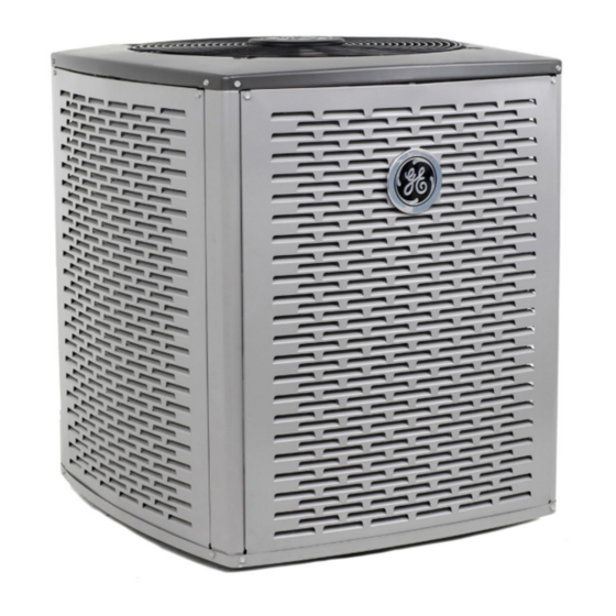
- Page 1 NS18HM Service VARIABLE SPEED HIGH Manual EFFICIENCY SPLIT HEAT PUMP SYSTEM UP TO 20 SEER & 10 HSPF READ CAREFULLY. KEEP THESE INSTRUCTIONS 31-5000751 Rev. 0 11-22 GEA...
-
Page 2: Table Of Contents
SERVICE MANUAL NS18HM This is a safety alert symbol and should never be ignored. When you see this symbol on labels or in manuals, be alert to the potential for personal injury or death. Table of Contents WARNING Technical Specifications ..........3 Parts Arrangement............6 Improper installation, adjustment, alteration, service General ................9... -
Page 3: Technical Specifications
Technical Specifications MODEL NUMBER GUIDE N S S 18 H H 36 36 M M – – XX BRAND MAJOR / MINOR REVISION N-GE PRODUCT REFRIGERANT S-SPLIT 4-R410A SEER VOLTAGE A-208/230 1PH 60HZ APPLICATION DESIGN VARIANT H-HEAT PUMP M-MODULATING COOLING CAPACITY (1000BTU/HR) 36, 60 ELECTRICAL AND PHYSICAL DATA... - Page 4 SOUND RATINGS Estimated Sound Pressure (dBA) Approximate Distance Model Sound Power One Meter Two Meters Three Meters (3.3 feet) (6.6 feet) (9.8 feet) NS18H36MA4 (2 TON MODE) NS18H36MA4 (3 TON MODE) NS18H60MA4 (4 TON MODE) NS18H60MA4 (5 TON MODE) 1 Rated in accordance with AHRI standard 270 (2015) 2 Rated in accordance with AHRI standard 275 (2010) 3 Based only on distance factor;...
- Page 5 ACCESSORIES Description Where Used Kit Number Purpose Prevents liquid migration to compressor in cold Crankcase heater All models Factory installed weather Sound Blanket All models Factory installed Lowers compressor sound level Short Cycle Protector All models Control Board Feature Protects compressor from short cycling. Prevents liquid migration to the compressor Liquid Line Solenoid All models...
-
Page 6: Parts Arrangement
Parts Arrangement Outdoor Control Board Inverter Contactor Inverter Reactor Voltage Connections Ground Lug Voltage Vent Grommet Figure 1. Parts Arrangement - Control Panel Page 6 31-5000751 Rev. 0... - Page 7 Accumulator Suction Pressure Transducer Compressor Low Pressure Switch Muffler Check Valve Suction High Pressure Filter Switch Reversing Crankcase Heater Valve Thermostat Liquid Service Valve Vapor Service Liquid Pressure Valve Transducer Figure 2. Parts Arrangement - 3 Ton Page 7 31-5000751 Rev. 0...
- Page 8 Compressor Temperature Limit Compressor High Pressure Switch Muffler Suction Pressure Transducer Reversing Valve Pressure Switch Liquid Pressure Liquid Transducer Service Valve NOTE: Crankcase Heater Vapor Service Valve Thermostat located between Liquid Service Valve and Liquid Pressure Transducer Figure 3. Parts Arrangement - 5 Ton Page 8 31-5000751 Rev.
-
Page 9: General
Handle refrigerant with caution; refer to proper MSDS General from refrigerant supplier. Use care when lifting, avoid contact with sharp edges. Read this entire instruction manual, as well as the instructions supplied in separate equipment, before Installation starting the installation. Observe and follow all warnings, cautions, instructional labels, and tags. - Page 10 If conditions or local codes require the unit be attached to pad or mounting frame, tie down bolts should be used and IMPORTANT secured to unit base pan. Exhaust vents from dryers, water heaters and furnaces Elevate Unit should be directed away from the outdoor unit. Prolonged exposure to exhaust gases and the chemicals contained within them may cause condensation to form CAUTION...
-
Page 11: Refrigerant Piping
DO LOCATE THE UNIT: • Ensure that tubing insulation is pliable and completely surrounds vapor tube. • With proper clearances on sides and top of unit It is important that no tubing be cut or seals broken until you • On a solid, level foundation or pad (unit must be level are ready to actually make connections to the evaporator to within ±... - Page 12 NOTE: Length is general guide. Lengths may be more or less, depending on remaining system design WARNING factors. Polyvinyl ether (PVE) oils used with HFC-410A • Maximum linear (actual) length = 150 feet. refrigerant absorb moisture very quickly. It is very •...
- Page 13 Total Linear Length (ft.) Liquid Line Tonnage SIze 3/8” 3/8” 1/2” 3/8” 1/2” 3/8” 1/2” NOTE: Shaded rows indicate rated liquid line size. A. Find your tonnage on the left side of the table. B. Start with the rated liquid line size (shaded row) on the outdoor tonnage. C.
- Page 14 Flushing Line Sets Disconnect the liquid line from the expansion valve at the liquid line assembly. If the unit will be installed in an existing system that uses an indoor unit or line sets charged with R-22 refrigerant, Disconnect the expansion valve from the liquid line installer must perform the following flushing procedure.
- Page 15 Refrigerant Piping - Install Indoor Expansion Valve This outdoor unit is designed for use in systems that include a heat pump expansion valve metering device at the indoor coil. See the Product Specifications for approved expansion valve kit match-ups and application information. The expansion valve unit can be installed internal or external to the indoor coil.
- Page 16 Refrigerant Piping - Brazing Procedures CAP AND CORE REMOVAL CUT AND DEBUR Cut ends of the refrigerant lines square (free from nicks or dents) Remove service cap and core from and debur the ends. The pipe must remain round. Do not crimp end both the vapor and liquid line service of the line.
- Page 17 WRAP SERVICE VALVES To help protect service valve seals during brazing, wrap water-saturated cloths around service valve bodies and copper tube stubs. Use additional water-saturated cloths underneath the valve body to protect the base paint. FLOW NITROGEN Flow regulated nitrogen (at 1 to 2 psig) through the refrigeration gauge set into the valve stem port connection on the liquid service valve and out of the vapor valve stem port.
- Page 18 Leak Test and Evacuation LEAK TEST HIGH MANIFOLD GAUGE SET OUTDOOR UNIT TO VAPOR SERVICE VALVE NOTE - Position canister to deliver liquid refrigerant. NITROGEN HFC-410A CONNECT GAUGE SET A - Connect the high pressure hose of an HFC-410A manifold gauge set to the vapor valve service port. NOTE - Normally, the high pressure hose is connected to the liquid line port.
- Page 19 EVACUATION HIGH CONNECT GAUGE SET NOTE - Remove cores from service valves (if not already done). A - Connect low side of manifold gauge set with 1/4 SAE in-line tee to vapor line service valve B - Connect high side of manifold gauge set to OUTDOOR MANIFOLD liquid line service valve...
-
Page 20: Electrical - Circuit Sizing And Wire Routing
NS18HM Low Voltage Control Wiring Electrical - Circuit Sizing and Wire Routing Connections The NS18HM variable capacity units are provided with In the U.S.A., wiring must conform with current local codes (2) RAST 6-Pin connections for connecting the field low and the current National Electric Code (NEC). - Page 21 Qty. of NS18HM Terminal Field Wiring Thermostat Type Indoor Unit Type Wires to Unit Operation Strip Connections Diagram NS18HM Conventional Full Variable Capacity Operation 24VAC 2-Stage Any Furnace or Air R, C, W1, O, Y1, Y2 Controlled by NS18HM Unitary Figure 13 Heat Pump Handler...
- Page 22 OUTDOOR UNIT CONNECT CONDUIT TO CUTOUT AND ROUTE HIGH CONNECTS TO VOLTAGE WIRING (2) RAST 6-PIN CONNECTORS LOW VOLTAGE MAKE-UP BOX GROMMET AND CABLE TIE ROUTE CONTROL WIRING THROUGH USE WATERTIGHT GROMMET AND CONDUIT FOR HIGH SECURE WITH VOLTAGE CABLE TIE Figure 11.
- Page 23 ACC2 ACC2 ACC1 ACC1 RAST 6-PIN RAST 6-PIN CONNECTOR CONNECTOR RAST 6-PIN RAST 6-PIN CONNECTOR CONNECTOR VARIABLE CAPACITY TWO STAGE / CONVENTIONAL 24VAC VARIABLE CAPACITY TWO STAGE / CONVENTIONAL 24VAC OUTDOOR UNIT VARIABLE SPEED HEAT PUMP THERMOSTAT OUTDOOR UNIT VARIABLE SPEED HEAT PUMP THERMOSTAT GAS FURNACE GAS FURNACE...
-
Page 24: Outdoor Unitary Control
Outdoor Unitary Control Jumpers and Terminals 7 SEGMENT DISPLAY CHARGE MODE JUMPER (CHRG MODE) CHARGE MODE AND OPERATION MODE JUMPER DETAIL OPERATION MODE JUMPER PUSH BUTTON RAST TERMINALS FOR THERMOSTAT WIRING CONNECTION Figure 14. 7-Segment Display and Push Button Information labels concerning outdoor... - Page 25 Exiting Charge Mode The unit will display the unit type for 10 seconds. Press the push button and hold it for 3 seconds for the unit To exit the charging mode, remove the Charge Mode to store the unit type. Once, the unit code is stored Jumper from the Charge Mode Pins.
-
Page 26: Unit Operation
Heating Operation Mode Jumper Unit Operation The Heating Operation Mode Jumper is only used on applications installed with a conventional 24VAC heat pump thermostat. In applications with a conventional NS18HM Unit Operation with a Conventional 24VAC heat pump thermostat, the compressor capacity is 24VAC 2-Stage Thermostat controlled to maintain the target liquid pressure setpoint. - Page 27 monitors ambient temperature, outdoor coil temperature minutes. No change is he frost accumulation time is made along with the compressor run time in heating mode if the frost accumulation time is close to the target defrost and defrost cycle time. The outdoor unit control monitors cycle time (between 80% and 120% of the target defrost compressor run time in the heating mode when the cycle time).
- Page 28 WARNING - Electric Shock Hazard. Can cause injury or death. Unit must be grounded in accordance with national and local codes. The 4 pins in P6 have the potential of transferring up to 250 volts to the unit cabinet ground. Designator Description Input...
- Page 29 WARNING - Electric Shock Hazard. Can cause injury or death. Unit must be grounded in accordance with national and local codes. The 4 pins in P6 have the potential of transferring up to 250 volts to the unit cabinet ground. Designator Description Input...
-
Page 30: Servicing Units Delivered Void Of Charge
WARNING - Electric Shock Hazard. Can cause injury or death. Unit must be grounded in accordance with national and local codes. The 4 pins in P6 have the potential of transferring up to 250 volts to the unit cabinet ground. Designator Description Input... -
Page 31: System Operation And Service
System Operation and Service 7-Segment Alert and System Status Codes Manual reset can be achieved by one of the following Alert codes are displayed using the 7-segment display methods: located on the outdoor control. • Disconnecting R wire from the outdoor control R terminal. - Page 32 GF= Gas Furnace, AH=Air Handler, ID=Indoor unit (GF or AH), HP=Heat Pump, AC=Air Conditioner, OD=Outdoor Unit (AC or HP), ZA=Zone system and TS=Thermostat Inverter Flash Code Alert Inverter Priority Actual Displayed Component or System Operational State How to Clear Code Code Condition Alert Text...
- Page 33 GF= Gas Furnace, AH=Air Handler, ID=Indoor unit (GF or AH), HP=Heat Pump, AC=Air Conditioner, OD=Outdoor Unit (AC or HP), ZA=Zone system and TS=Thermostat Inverter Flash Code Alert Inverter Priority Actual Displayed Component or System Operational State How to Clear Code Code Condition Alert Text...
- Page 34 GF= Gas Furnace, AH=Air Handler, ID=Indoor unit (GF or AH), HP=Heat Pump, AC=Air Conditioner, OD=Outdoor Unit (AC or HP), ZA=Zone system and TS=Thermostat Inverter Flash Code Alert Inverter Priority Actual Displayed Component or System Operational State How to Clear Code Code Condition Alert Text...
- Page 35 GF= Gas Furnace, AH=Air Handler, ID=Indoor unit (GF or AH), HP=Heat Pump, AC=Air Conditioner, OD=Outdoor Unit (AC or HP), ZA=Zone system and TS=Thermostat Inverter Flash Code Alert Inverter Priority Actual Displayed Component or System Operational State How to Clear Code Code Condition Alert Text...
- Page 36 GF= Gas Furnace, AH=Air Handler, ID=Indoor unit (GF or AH), HP=Heat Pump, AC=Air Conditioner, OD=Outdoor Unit (AC or HP), ZA=Zone system and TS=Thermostat Inverter Flash Code Alert Inverter Priority Actual Displayed Component or System Operational State How to Clear Code Code Condition Alert Text...
- Page 37 GF= Gas Furnace, AH=Air Handler, ID=Indoor unit (GF or AH), HP=Heat Pump, AC=Air Conditioner, OD=Outdoor Unit (AC or HP), ZA=Zone system and TS=Thermostat Inverter Flash Code Alert Inverter Priority Actual Displayed Component or System Operational State How to Clear Code Code Condition Alert Text...
- Page 38 GF= Gas Furnace, AH=Air Handler, ID=Indoor unit (GF or AH), HP=Heat Pump, AC=Air Conditioner, OD=Outdoor Unit (AC or HP), ZA=Zone system and TS=Thermostat Inverter Flash Code Alert Inverter Priority Actual Displayed Component or System Operational State How to Clear Code Code Condition Alert Text...
- Page 39 GF= Gas Furnace, AH=Air Handler, ID=Indoor unit (GF or AH), HP=Heat Pump, AC=Air Conditioner, OD=Outdoor Unit (AC or HP), ZA=Zone system and TS=Thermostat Inverter Flash Code Alert Inverter Priority Actual Displayed Component or System Operational State How to Clear Code Code Condition Alert Text...
- Page 40 GF= Gas Furnace, AH=Air Handler, ID=Indoor unit (GF or AH), HP=Heat Pump, AC=Air Conditioner, OD=Outdoor Unit (AC or HP), ZA=Zone system and TS=Thermostat Inverter Flash Code Alert Inverter Priority Actual Displayed Component or System Operational State How to Clear Code Code Condition Alert Text...
- Page 41 GF= Gas Furnace, AH=Air Handler, ID=Indoor unit (GF or AH), HP=Heat Pump, AC=Air Conditioner, OD=Outdoor Unit (AC or HP), ZA=Zone system and TS=Thermostat Inverter Flash Code Alert Inverter Priority Actual Displayed Component or System Operational State How to Clear Code Code Condition Alert Text...
- Page 42 GF= Gas Furnace, AH=Air Handler, ID=Indoor unit (GF or AH), HP=Heat Pump, AC=Air Conditioner, OD=Outdoor Unit (AC or HP), ZA=Zone system and TS=Thermostat Inverter Flash Code Alert Inverter Priority Actual Displayed Component or System Operational State How to Clear Code Code Condition Alert Text...
- Page 43 POWER-UP / RESET: 7-SEGMENT POWER-UP DISPLAY STRING FIRMWARE VERSION: During initial power-up or reset, the first item displayed is the outdoor control firmware version. Example to the right shows firmware version 2.3. UNIT TYPE: The next item displayed is the self discovery unit type.
- Page 44 Description Example of Display Idle Mode: Decimal point flashes at 1 Hz (0.5 second on, 0.5 second off). Idle Mode: Decimal point flashes at 1 Hz. Display OFF. All segments flashing at 2 Hz (unless error is detected). NOTE - Control O.E.M.
- Page 45 Idle mode – System is energized with no demand – Decimal flashes at 1 Hertz > 0.5 second ON. 0.5 second OFF Display Symbol Display Fan Test and Display String Option or Character Displayed during Display string shows outdoor control firmware version 1 _ 6 > pause > A C or H P unit > pause > unit capacity in BTUs > pause start-up or power >...
-
Page 46: Configuring Unit
Configuring Unit When installing a replacement outdoor control, the unit selection code may have to be manually assigned using the 7-segment display and push button on the control. The unit code sets unit type, capacity and outdoor fan profile. Configuring Unit Selection Code Power-up - Unit selection code (two-digit number) displayed represents unit size code (outdoor unit capacity). -
Page 47: Maintenance
Maintenance Regular Maintenance Requirements Your system should be regularly inspected by a qualified Remove two service technician. These regular visits may include screws at top (among other things) checks for: panel to remove • Motor operation louvers for coil access. •... - Page 48 Heat Pump Operation System Switch Your new heat pump has several characteristics that you Set the system switch for heating, cooling or auto should be aware of: operation. The auto mode allows the heat pump to automatically switch from heating mode to cooling mode to •...
-
Page 49: Wiring Diagram
Wiring Diagram Figure 20. Wiring Diagram Page 49 31-5000751 Rev. 0... -
Page 50: Unit Sequence Of Operation
Unit Sequence of Operation The following figures illustrate the overall unit sequence of operation along with the operation of various pressure switches and temperature sensors. The figures also illustrate the use of the compressor anti-short-cycle function in relation to unit Status, unit Fault and lockout LED Codes and unit system operation interactions. - Page 51 SUCTION Y1 DEMAND PRESSURE OR COOLING PRESSURE CONTACTOR CUT-OUT IS CLOSED DEMAND CLOSED IGNORED FOR ENERGIZED (S87) 90 SECONDS SWITCH IS CLOSED OR LOW PRESSURE OUTDOOR AMBIENT OPEN (S87) CLOSED TEMPERATURE IS 15ºF OR BELOW CONTACTOR DE-ENERGIZED The thermostat terminates demand when the contactor is de-energized.
- Page 52 HIGH Y1 DEMAND TOP CAP PRESSURE CONTACTOR OR COOLING CLOSED CLOSED SWITCH (S173) SWITCH (S4) ENERGIZED DEMAND HIGH PRESSURE CLOSED OPEN SWITCH (S4) CONTACTOR DE-ENERGIZED The thermostat terminates demand when the contactor is de-energized. If demand is satisfied when alarm is not active, the OPEN 5-strike counter resets.
- Page 53 START DEFROST IF DEFROST CYCLE TIME IS STATE CLOSE TO TARGET DEFROST CYCLE TIME (BETWEEN 80% - 120% TARGET DEFROST CYCLE TIME) – NO CHANGE IN FROST ACCUMULATION TIME ACCUMULATE FROST ACCUMULATION TIME – HP RUN TIME IF COIL TEMP BELOW 35°F IF DEFROST CYCLE TIME IS SHORT (80% OR LESS OF TARGET DEFROST CYCLE TIME)
-
Page 54: Component Testing
Component Testing Component Testing Table of Contents Verifying High Pressure Switch and Low Pressure Liquid Line Filter Drier ..........62 Protection Operation..........51 Top Cap Switch Operation, Checkout and Status / Error Verifying Suction Pressure Transducer Operation..52 Codes ................63 Verifying Liquid Pressure Transducer Operation ..53 Reactor Operations, Checkout and Status / Error Codes High Pressure Switch and Low Pressure Protection ...................64... -
Page 55: Verifying Suction Pressure Transducer Operation
Verifying Suction Pressure Transducer Operation Using a multimeter set to VDC with the Suction Pressure Transducer connected to the “Suct P” 3-pin connector on the control board. Pin 1 (Red wire +5VDC) to Pin 3 (Black wire - GND) should read 5 VDC continuous. Pin 2 (Blue wire output from transducer) to Pin 3 (Black - GND) should read 0.5 to 4.5 VDC and will vary depending on suction pressure measured. -
Page 56: Verifying Liquid Pressure Transducer Operation
Verifying Liquid Pressure Transducer Operation Using a multimeter set to VDC with the Liquid Pressure Transducer connected to the “Liq P” 3-pin connector on the control board. Pin 1 (Red wire +5VDC) to Pin 3 (Black wire - GND) should read 5 VDC continuous. Pin 2 (Blue wire output from transducer) to Pin 3 (Black - GND) should read 0.5 to 4.5 VDC and will vary depending on liquid~ pressure measured. -
Page 57: High Pressure Switch And Low Pressure Protection Errors
High Pressure Switch and Low Pressure Protection Errors GF= Gas Furnace, AH=Air Handler, ID=Indoor unit (GF or AH), HP=Heat Pump, AC=Air Conditioner, OD=Outdoor Unit (AC or HP), ZA=Zone system and TS=Thermostat Inverter Alert Priority Actual Displayed How to Clear Alert Flash Component or System Operational State and Troubleshooting Tip Code... - Page 58 SCROLL ROTARY COMPRESSOR COMPRESSOR (NS18H60 only) 0.883 0.883 0.883 NS18H36 0.587 0.587 0.587 NS18H60 Figure 28. IMPORTANT: If compressor replacement is required, remove the compressor through the top of the unit. Removal through the access panel is not possible. ELECTRICAL CONNECTION PLUG LOCATION...
-
Page 59: Compressor Equalization Valve
Compressor Equalization Valve The compressor equalization valve equalization solenoid equalizes the pressure across the rotary compression chamber allowing the compressor to start unloaded. The 240 VAC solenoid coil is controlled by the inverter. The solenoid coil is powered when the compressor is off to equalize the pressure and is de-energized when the compressor is operating. STATUS CODES: When the compressor is running, the 7-segment display will show the compressor capacity. - Page 60 GF= Gas Furnace, AH=Air Handler, ID=Indoor unit (GF or AH), HP=Heat Pump, AC=Air Conditioner, OD=Outdoor Unit (AC or HP), ZA=Zone system and TS=Thermostat Inverter Flash Code Alert Inverter Priority Actual Displayed How to Clear Alert Component or System Operational State and Troubleshooting Tip Code Code Condition...
- Page 61 GF= Gas Furnace, AH=Air Handler, ID=Indoor unit (GF or AH), HP=Heat Pump, AC=Air Conditioner, OD=Outdoor Unit (AC or HP), ZA=Zone system and TS=Thermostat Inverter Flash Code Alert Inverter Priority Actual Displayed How to Clear Alert Component or System Operational State and Troubleshooting Tip Code Code Condition...
- Page 62 GF= Gas Furnace, AH=Air Handler, ID=Indoor unit (GF or AH), HP=Heat Pump, AC=Air Conditioner, OD=Outdoor Unit (AC or HP), ZA=Zone system and TS=Thermostat Inverter Flash Code Alert Inverter Priority Actual Displayed How to Clear Alert Component or System Operational State and Troubleshooting Tip Code Code Condition...
-
Page 63: Crankcase Heater, Checkout And Status / Error Codes
Crankcase Heater, Checkout and Status / Error Codes OPERATION: Crankcase Heater (HR1) Compressors in all units are equipped with a 40 watt belly-band type crankcase heater. The heater prevents liquid from accumulating in the compressor. The heater is controlled by the crankcase heater thermostat. Crankcase Heater Thermostat (S40) Crankcase heater thermostat S40 controls the crankcase heater in all units and is located on the liquid line (see Figure 2 and Figure 3 for locations). -
Page 64: Suction Line Filter Drier
Figure 33. Checking Crankcase Heater Thermostat STATUS CODE: None ERROR CODES: None Compressor Sound Cover All units come with a soft-sided polyethylene molded outer shell compressor sound cover. The cover helps reduce any unwanted operating sounds from the compressor. The cover features a hook/loop closure system for ease of installation on the compressor. -
Page 65: Top Cap Switch Operation, Checkout And Status / Error Codes
The NS18HM models with a rotary compressor do not have a factory installed liquid filter drier and it is not required on these models. A liquid line filter drier on the rotary compressor models may be field installed if desired. FIGURE 36. -
Page 66: Reactor Operations, Checkout And Status / Error Codes
NOTE - System fault and lockout codes take precedence over system status codes (cooling, heating operating percentages or defrost/dehumidification). Only the latest active fault or lockout codes are displayed (if present). If no fault or lockout codes are active, then system status codes are displayed. Alert codes are also displayed on the communicating thermostat. - Page 67 LOW AMBIENT OPERATION: The NS18HM units have factory installed low ambient cooling mode operation that will control the condenser fan motor based upon liquid line temperature. The NS18HM units have a variable speed ECM fan motor. The outdoor control will begin to modulate the outdoor fan motor speed is below 65°F to maintain a liquid line sensor temperature between 58°F and 70°F.
-
Page 68: Outdoor Control Operation, Checkout And Status / Error Codes
Outdoor Control Operation, Checkout and Status / Error Codes OPERATION: The outdoor control is a microprocessor-based device for use with variable-capacity compressors up to 5-tons in capacity operating on 24VAC residential power. The outdoor control integrates the functionality of maintaining compressor speed, and outdoor fan control of ECM motors. -
Page 69: Unit Sensor Operation, Checkout And Status /Error Codes
Unit Sensor Operation, Checkout and Status /Error Codes OPERATION: 6-Pin Sensor Harness (LIQ, AMB, COIL) Liquid Sensor (R7 - No Sensor) There is no sensor located on positions 5 and 6 of the connector. A 10K Ohm resistor installed between pins 5 and 6 on the cable harness provides continuity for this circuit. - Page 70 NOTE: When checking the ohms across a sensor, be aware that a sensor showing a resistance value that is not within the range shown in figure 49, may be performing as designed. However, if a shorted or open circuit is detected, then the sensor may be faulty and the sensor harness will need to be replaced.
- Page 71 Resistance Resistance Resistance Resistance enheit enheit enheit enheit 136.3 2680 56.8 16657 21.6 44154 -11.3 123152 133.1 2859 56.0 16973 21.0 44851 -11.9 125787 130.1 3040 55.3 17293 20.5 45560 -12.6 128508 127.3 3223 54.6 17616 20.0 46281 -13.2 131320 124.7 3407 53.9...
-
Page 72: Dc Inverter Control Operation, Checkout, Status / Error Codes
NOTE - System fault and lockout codes take precedence over system status codes (cooling, heating operating percentages or defrost/dehumidification). Only the latest active fault or lockout codes are displayed (if present). If no fault or lockout codes are active, then system status codes are displayed. Alert codes are also displayed on the communicating thermostat. - Page 73 GF= Gas Furnace, AH=Air Handler, ID=Indoor unit (GF or AH), HP=Heat Pump, AC=Air Conditioner, OD=Outdoor Unit (AC or HP), ZA=Zone system and TS=Thermostat Inverter Flash Code Alert Inverter Priority Actual Displayed Component or System Operational State and Troubleshooting How to Clear Alert Code Code Condition...
- Page 74 GF= Gas Furnace, AH=Air Handler, ID=Indoor unit (GF or AH), HP=Heat Pump, AC=Air Conditioner, OD=Outdoor Unit (AC or HP), ZA=Zone system and TS=Thermostat Inverter Flash Code Alert Inverter Priority Actual Displayed Component or System Operational State and Troubleshooting How to Clear Alert Code Code Condition...
- Page 75 GF= Gas Furnace, AH=Air Handler, ID=Indoor unit (GF or AH), HP=Heat Pump, AC=Air Conditioner, OD=Outdoor Unit (AC or HP), ZA=Zone system and TS=Thermostat Inverter Flash Code Alert Inverter Priority Actual Displayed Component or System Operational State and Troubleshooting How to Clear Alert Code Code Condition...
- Page 76 GF= Gas Furnace, AH=Air Handler, ID=Indoor unit (GF or AH), HP=Heat Pump, AC=Air Conditioner, OD=Outdoor Unit (AC or HP), ZA=Zone system and TS=Thermostat Inverter Flash Code Alert Inverter Priority Actual Displayed Component or System Operational State and Troubleshooting How to Clear Alert Code Code Condition...
- Page 77 GF= Gas Furnace, AH=Air Handler, ID=Indoor unit (GF or AH), HP=Heat Pump, AC=Air Conditioner, OD=Outdoor Unit (AC or HP), ZA=Zone system and TS=Thermostat Inverter Flash Code Alert Inverter Priority Actual Displayed Component or System Operational State and Troubleshooting How to Clear Alert Code Code Condition...
- Page 78 GF= Gas Furnace, AH=Air Handler, ID=Indoor unit (GF or AH), HP=Heat Pump, AC=Air Conditioner, OD=Outdoor Unit (AC or HP), ZA=Zone system and TS=Thermostat Inverter Flash Code Alert Inverter Priority Actual Displayed Component or System Operational State and Troubleshooting How to Clear Alert Code Code Condition...
- Page 79 GF= Gas Furnace, AH=Air Handler, ID=Indoor unit (GF or AH), HP=Heat Pump, AC=Air Conditioner, OD=Outdoor Unit (AC or HP), ZA=Zone system and TS=Thermostat Inverter Flash Code Alert Inverter Priority Actual Displayed Component or System Operational State and Troubleshooting How to Clear Alert Code Code Condition...
- Page 80 GF= Gas Furnace, AH=Air Handler, ID=Indoor unit (GF or AH), HP=Heat Pump, AC=Air Conditioner, OD=Outdoor Unit (AC or HP), ZA=Zone system and TS=Thermostat Inverter Flash Code Alert Inverter Priority Actual Displayed Component or System Operational State and Troubleshooting How to Clear Alert Code Code Condition...
- Page 81 GF= Gas Furnace, AH=Air Handler, ID=Indoor unit (GF or AH), HP=Heat Pump, AC=Air Conditioner, OD=Outdoor Unit (AC or HP), ZA=Zone system and TS=Thermostat Inverter Flash Code Alert Inverter Priority Actual Displayed Component or System Operational State and Troubleshooting How to Clear Alert Code Code Condition...
- Page 82 GF= Gas Furnace, AH=Air Handler, ID=Indoor unit (GF or AH), HP=Heat Pump, AC=Air Conditioner, OD=Outdoor Unit (AC or HP), ZA=Zone system and TS=Thermostat Inverter Flash Code Alert Inverter Priority Actual Displayed Component or System Operational State and Troubleshooting How to Clear Alert Code Code Condition...
- Page 83 HFC-410A CHARGING INFORMATION – NS18H36M FOR COMPLETE CHARGING PROCEDURES, REFER TO THE APPLICABLE INSTALLATION AND SERVICE MANUAL Maintenance checks using the Normal Operating Pressures table • Table 1 may be used to help perform maintenance checks. This table is not a procedure for charging the system. Minor variations in the pressures can be expected due to differences in installations.
- Page 84 HFC-410A CHARGING INFORMATION – NS18H60M FOR COMPLETE CHARGING PROCEDURES, REFER TO THE APPLICABLE INSTALLATION AND SERVICE MANUAL Maintenance checks using the Normal Operating Pressures table • Table 1 may be used to help perform maintenance checks. This table is not a procedure for charging the system. Minor variations in the pressures can be expected due to differences in installations.
- Page 85 Notes Page 85 31-5000751 Rev. 0...
- Page 86 All specifications and illustrations subject to change without notice and without incurring obligations. Printed in the U.S.A.