Advertisement
Quick Links
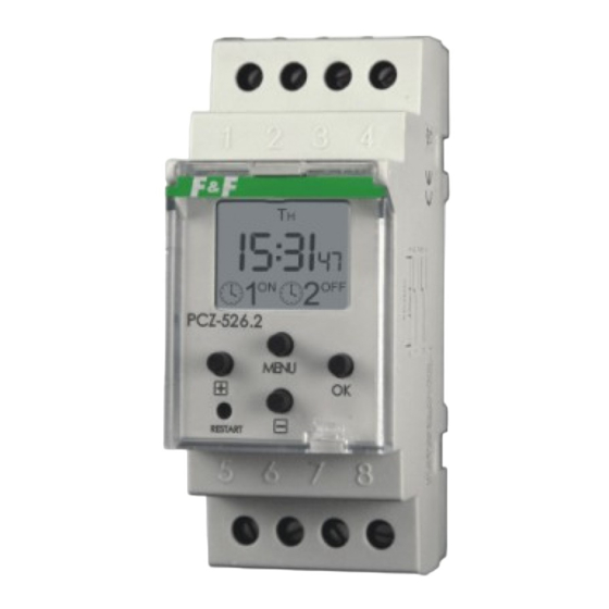
PCZ-526.2
PROGRAMMABLE CONTROL TIMERS
astronomic type
5
9 0 8 3 1 2
www.fif.com.pl
F&F products are covered by an 24 months warranty from date of purchase
PURPOSE
Astronomical control timers is as for enclosing and switching off of
illumination or according to other electric receivers 24 hours,
astronomical points of west and sunrise
t
night break
joint 1-5
programmable
t
1
enclosing
point
ATTENTION!
It touches east and they are defined sunset as moment, when it
touches center of sunny disk horizon it ( parameter h = - 0,583 ° ).
Deviation of row several minute commits from the point of view of
simplification of account relatively to data by indicated „HM Nautical
Almanac Office".
DESCRIPTION OF WORK AND FUNCTIONS
AUTOMATIC WORK - according to program points of enclosures and
switching off joint [sign
ş
on the left of display]
HANDIWORK- [ON] - enduring connection of joint (position1-5) or [OFF]-
enduring switch off joint (position 1-6) by activated AUTOMATIC WORK [
lack of sign
ş on the left of display]
PROGRAMMABLE
POINT OF ENCLOSURE - time of enclosure in
foothold about astronomical point of sunset indicated joint (position
1-5) and HOUR SLIP by user program and TIME CORRECTION.
PROGRAMMABLE POINT OF EXCLUSION- time of exclusion in foothold
about astronomical point of sunset indicated joint (position1
-6) and HOUR SLIP by user program and TIME CORRECTION.
CONFIGURATION - application of LOCALIZATION and assignment of
POINT OF PROGRAM ENCLOSURE and EXCLUSION
LOCALIZATION - application of CODE COORDINATES or manual optional
setups geographic coordinates ( for CODE COORDINATES 86 - SITE
USER )
COORDINATES
CODE - for detailed cities assign city geographic
facilitating inscription localization (coordinates and assign serve codes in
table memorial )
HOUR SLIP
- assignment of geographic time zone in range ±1÷12
relatively to universal time greenwich UT (00). For poland + 1 hour. Points
of time east and sunset they undergo parallel slip about served value .
TIME CORRECTION - acceleration or delay of time of enclosure or
relatively to astronomical time points of east exclusion (switching off) and
sunset. Setups in range
±99min for point of west and sunrise are
performed in apart.
DST - Daylight Saving Time - global name of summer time (free translation
time of winning sunny light). Function enabling exclusion automatic change
time.
NIGHT BREAK - set by user time of programming points of enclosure and
exclusion.
CHANNEL - user programming line with sets in KONFIGURATION MODE
and NIGHT BREAK sterring a enclosure joint.
F&F Filipowski sp. j.
ul. Konstantynowska 79/81
95-200 Pabianice POLAND
tel/fax +48 42 2152383; 2270971
e-mail: fif@fif.com.pl
(S)
5 9 6 4 2 4
t
programmable
2
exclusioning
point
FUNCTIONING
The astronomical timer activates and deactivates a device at certain
hour, i.e. at sunrise and sunset. Should more settings that are precise
be required for locations of different geographical co-ordinates, there
is an option to set a given longitude and latitude or select a special
code which entails automatic setting of these co-ordinates for a given
place in Europe (list of locations and their codes may be found in the
manual). Time points of enclosing and exclusion are set by user by
HOUR SLIP MODE or TIME CORRECTION MODE it means , posible
is speed up or delay a programmable time points of enclosing or
exlusioning for sunrise and sunset. Posible is programming a night
break between enclusion and exclusion programming points ( take
off the power for hour to austerity energy).
TECHNICAL DATA
supply
current load
contacts
display maintenance time
timer maintenance time
indication accuracy item
time deviation
schedule time accurancy item
corection activation and deactivation time
power consumption
working temperature
connection
dimensions
fixing
WIRING DIAGRAM
Chanell 1:
joint 1-5 "ENCLOSE" [ON]
joint 1-6 "EXCLUSION" [OFF]
Chanell 2:
joint 2-7 "ENCLOSE" [ON]
joint 2-8 "EXCLUSION" [OFF]
ASSEMBLY
1. Take OFF the power.
2. Put on the control timer on the rail in the switchgear box.
3. Connect the power cables with wiring diagram.
4 Connect the recuivers with wiring diagram.
5.Set a correct date (see p. 2) and time (see p3)
6.Set to user configuration (see p4)
24÷264V AC/DC
2×(<16A)
2×
1P
non
6 years
1sec
±1s/24h
1min
±0÷99min
1,5W
-20÷50°C
screw terminals 2
,5mm²
2 modules (35mm)
on the rail TH-35
AC/DC
1
2
3
4
5
6
7
8
Advertisement

Related Manuals for F&F PCZ-526.2 (S)


Summary of Contents for F&F PCZ-526.2 (S)
- Page 1 FUNCTIONING F&F Filipowski sp. j. ul. Konstantynowska 79/81 The astronomical timer activates and deactivates a device at certain 95-200 Pabianice POLAND tel/fax +48 42 2152383; 2270971 hour, i.e. at sunrise and sunset. Should more settings that are precise e-mail: fif@fif.com.pl be required for locations of different geographical co-ordinates, there is an option to set a given longitude and latitude or select a special PCZ-526.2...
- Page 2 RESET: DESCRIPION OF DISPLAY AND PANEL STEERING - to reset a processor - in case of hook-up of function of work indispensable of timer. It does not erase setups of dates and time and registration settings. date and time/ Mo T −+ MENU ("hard"...
- Page 3 Mo T 5. CONFIGURATION - set to CORRECTION OF TIME, PROG LOCALIZATION AND HOUR DELAY. Change CONFIGURATION by prees MENU >3sec. ATTENTION! C hanges of CONFIGURATION mode are previoused By buttons +/− set to code and enter by checking or changing a date (see p2.1), time (see p3.1) and option. 5.4 Timer pass to HOUR SLIP mode..
- Page 4 By buttons +/− set to minutes and enter OK.. 7. HANDIWORK SETTING GEOGRAFICAL COORDINATES 7.1 Pass to handiwork setting mode of geografical coordinates is 7.5 Z Timer pass to of setting mode of minutes of geografical lenght previoused by pass of CONFIGURATION MODE (see p5). In setting coordinates..
- Page 5 Code City Longitude Latitude Device OFF Finland Helsinki 60:08:00 °N 025:00:00 °E Finland Kuopio 62:54:00 °N 27:41:00 °E Finland Rovaniemi 66:33:07 ºN 25:50:51 ºE Norway Andenes 69:19:12 °N 16:07:12 °E 21.05÷23.07 Norway Alta 69:34:48 °N 23:15:00 °E 20.05÷21.07 Norway Bardufoss 69:02:24 °N 18:37:12 °E 22.05÷21.07...
Need help?
Do you have a question about the PCZ-526.2 (S) and is the answer not in the manual?
Questions and answers