NETGEAR ProSafe GS724TP Installation Manual
Smart switch
Hide thumbs
Also See for ProSafe GS724TP:
- Datasheet (3 pages) ,
- Software administration manual (216 pages) ,
- Hardware installation manual (36 pages)

Related Manuals for NETGEAR ProSafe GS724TP


Summary of Contents for NETGEAR ProSafe GS724TP
- Page 1 GS700TP Hardware Installation Guide NETGEAR, Inc. 4500 Great America Parkway Santa Clara, CA 95054 USA 202-10241-01 January 2007...
-
Page 2: Statement Of Conditions
In the interest of improving internal design, operational function, and/or reliability, NETGEAR reserves the right to make changes to the products described in this document without notice. NETGEAR does not assume any liability that may occur due to the use or application of the product(s) or circuit layout(s) described herein. -
Page 3: Table Of Contents
GS700TP Hardware Installation Guide About This Manual Conventions, Formats and Scope ... v How to Use This Manual ... vi How to Print this Manual ... vi Chapter 1 Introduction Overview ...1-1 Features ...1-2 Package Contents ...1-4 Chapter 2 Physical Description GS724TP Front and Back Panel Configuration ...2-5 Front and Back Panels ...2-5 GS748TP Front and Back Panel Configuration ...2-6... - Page 4 Step 4: Connecting Devices to the Switch ...4-16 Step 5: Installing an SFP GBIC Module ...4-16 Step 6: Applying AC Power ...4-17 Step 7: Managing the Switch through a Web Browser or the PC Utility for Initial Configuration 4-18 Appendix A Troubleshooting Troubleshooting Chart ...
-
Page 5: About This Manual
The NETGEAR ® GS700TP Installation Guide describes how to install, configure and troubleshoot the GS700TP Smart Switch. The information in this manual is intended for readers with intermediate computer and Internet skills. Conventions, Formats and Scope The conventions, formats, and scope of this manual are described in the following paragraphs: •... -
Page 6: How To Use This Manual
• button to access the full NETGEAR, Inc. online knowledge base for the product model. • Links to PDF versions of the full manual and individual chapters. - Page 7 – Your computer must have the free Adobe Acrobat reader installed in order to view and print PDF files. The Acrobat reader is available on the Adobe Web site at http://www.adobe.com. – Click the print icon in the upper left of the window. Tip: If your printer supports printing two pages on a single sheet of paper, you can save paper and printer ink by selecting this feature.
- Page 8 GS700TP Hardware Installation Guide viii v1.0, January 2007...
-
Page 9: Introduction
Congratulations on the purchase of the NETGEAR Smart Switch. The NETGEAR Smart Switch is a state-of-the-art, high-performance, IEEE-compliant network solution designed for users who require a large number of ports and want the power of Gigabit connectivity to eliminate bottlenecks, boost performance, and increase productivity. To simplify installation, the switch is shipped ready for use out of the box. -
Page 10: Features
Category 5 Unshielded Twisted-Pair (UTP) cable, but much longer for fiber connections using SFP GBIC modules. Features The following list identifies the key features of the NETGEAR Smart Switch. • 24/48 RJ-45 10/100/1000M auto sensing Giga switching ports. - Page 11 • Auto-sensing and auto-negotiating capabilities for all ports. • Auto Uplink™ on all ports to make the right connection. • Automatic address learning function to build the packet-forwarding information table. The table contains up to 4K Media Access Control (MAC) addresses. •...
-
Page 12: Package Contents
GS700TP Hardware Installation Guide Package Contents Figure 1-1 shows the package contents of the NETGEAR Smart Switch. Figure 1-1 Verify that the package contains the following: • NETGEAR Smart Switch • Rubber footpads for tabletop installation • Power cord •... -
Page 13: Physical Description
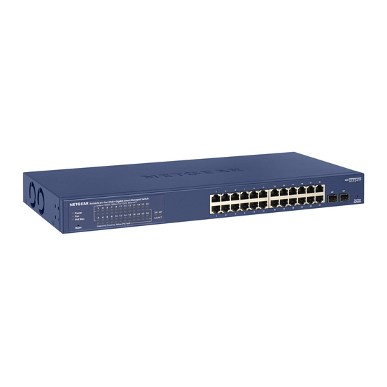
This chapter describes the NETGEAR Smart Switch hardware features. Topics include: • NETGEAR GS724TP Smart Switch front and back panel configuration • NETGEAR GS748TP Smart Switch front and back panel configuration • LED designations • Device hardware interfaces GS724TP Front and Back Panel Configuration The GS724TP is a 24-Ports 10/100/1000M + 2 SFP Combo ports Smart PoE switch .Every RJ45... -
Page 14: Gs748Tp Front And Back Panel Configuration
GS748TP Front and Back Panel Configuration The GS748TP is a 48-Port 10/100/1000M Smart PoE switch + 4 SFP Combo port switch. Every RJ45 port is capable of sensing the line speed and negotiating the operation duplex mode with the... - Page 15 • Port LEDs • System LEDs Figure 2-4 illustrates the NETGEAR GS748TP Smart Switch back panel: Figure 2-4 The back panel contains the following: • A 100-240VAC/50-60 Hz universal input, which is a standard AC power receptacle for accommodating the supplied power cord.
-
Page 16: Led Designations
GS700TP Hardware Installation Guide LED Designations Port LEDs The following table describes the port LED designations. Table 2-1. Port LEDs Port 24/48-10/100/1000 Ports SPD/Link/ACT LED - One LED/Port PoE Mode 2/4-SFP Ports - One SFP Link/ACT LED LED/Port Designation • Solid Green - A valid 1000Mbps link is established on the port. -
Page 17: System Leds
Device Hardware Interfaces RJ-45 Ports RJ-45ports are auto-sensing ports. When inserting a cable into an RJ-45 port, the switch automatically ascertains the maximum speed (10, 100 or 1000 Mbps) and duplex mode (half- or full-duplex) of the attached device. All ports support only unshielded twisted-pair (UTP) cable terminated with an 8-pin RJ-45 plug. -
Page 18: Sfp Gbic Module
The GBIC module bays accommodate standard SFP GBIC modules, such as the AGM731F, AGM732F, or AGM733 from NETGEAR, allowing fiber connections on the network. The module bay is a combo port, sharing a connection with an RJ-45 port. Being a combo port, only one type of connection can be active at any given time. -
Page 19: Applications
Chapter 3 Applications Your NETGEAR Smart Switch is designed to provide flexibility in configuring your network connections. It can be used as a stand-alone device or with 10 Mbps, 100 Mbps, and 1000 Mbps hubs and switches. 3-11 v1.0, January 2007... -
Page 20: Desktop Switching
GS700TP Hardware Installation Guide Desktop Switching The NETGEAR Smart Switch can be used as a desktop switch to build a small network that enables users to have 1000 Mbps access to a file server. With full-duplex enabled, the switch port connected to the server or PC can provide 2000 Mbps throughput. -
Page 21: Chapter 4 Installation
This chapter describes the installation procedures for your NETGEAR Smart Switch. Switch installation involves the following steps: Step 1: Preparing the site Step 2: Installing the switch Step 3: Checking the installation Step 4: Connecting devices to the switch Step 5: Installing an SFP GBIC module... -
Page 22: Step 2: Installing The Switch
Step 2: Installing the Switch The NETGEAR Smart Switch can be installed on a flat surface or in a standard 19-inch rack. Installing the Switch on a Flat Surface The switch ships with four self-adhesive rubber footpads. Stick one rubber footpad on each of the four concave spaces on the bottom of the switch. -
Page 23: Step 3: Checking The Installation
5. Tighten the screws with a #2 Phillips screwdriver to secure the switch in the rack. Figure 4-1 Step 3: Checking the Installation Before applying power perform the following: • Inspect the equipment thoroughly. • Verify that all cables are installed correctly. -
Page 24: Step 4: Connecting Devices To The Switch
Step 4: Connecting Devices to the Switch The following procedure describes how to connect PCs to the switch’s RJ-45 ports. The NETGEAR Smart Switch contains Auto Uplink™ technology, which allows the attaching of devices using either straight-through or crossover cables. -
Page 25: Step 6: Applying Ac Power
Figure 4-3 Step 6: Applying AC Power NETGEAR Smart Switch does not have an ON/OFF switch. The method of applying or removing AC power is by connecting or disconnecting the power cord. Before connecting the power cord, select an AC outlet that is not controlled by a wall switch, which can turn off power to the switch. -
Page 26: Step 7: Managing The Switch Through A Web Browser Or The Pc Utility For Initial Configuration
Step 7: Managing the Switch through a Web Browser or the PC Utility for Initial Configuration The NETGEAR Smart Switch contains software for viewing, changing, and monitoring the way it works. This management software is not required for the switch to work. The ports can be used without using the management software. -
Page 27: Appendix A Troubleshooting
This chapter provides information about troubleshooting the NETGEAR Smart Switch. Topics include the following: • “Troubleshooting Chart” • “Additional Troubleshooting Suggestions” Troubleshooting Chart The following table lists symptoms, causes, and solutions of possible problems. Table A-1. Troubleshooting Chart Symptom Cause Power LED is off. -
Page 28: Additional Troubleshooting Suggestions
AC power from the switch and then reapply AC power. If the problem continues, contact NETGEAR technical support. In North America, call 1-888-NETGEAR. If you are outside of North America, please refer to the support information card included with your product. -
Page 29: Auto-Negotiation
The RJ-45 ports negotiate the correct duplex mode and speed if the device at the other end of the link supports auto negotiation. If the device does not support auto negotiation, the switch only determines the speed correctly and the duplex mode defaults to half-duplex. - Page 30 GS700TP Hardware Installation Guide A-22 Troubleshooting v1.0, January 2007...
-
Page 31: Technical Specifications
Appendix B Technical Specifications Network Protocol and Standards Compatibility IEEE 802.3i 10Base-T IEEE 802.3u 100Base-TX,FX IEEE 802.3ab 1000Base-T IEEE 802.3z 1000Base-X IEEE 802.3x flow control IEEE 802.3af (DTE Power via MDI ) Management Windows 2000 + XP; Microsoft Explorer 6.0 IEEE 802.1p Class of Service (CoS) SNTP (Simple Network Time Protocol) 2 servers. - Page 32 GS700TP Hardware Installation Guide Mean Time Between Failure (MTBF): 167,355 hours for GS724TP, 125,566 hours for GS748TP Power Supply Power Consumption: 40W for GS724TP, 76.6W for GS748TP 100-240VAC/50-60 Hz universal input Physical Specifications Dimensions (H x W x D): GS724TP/GS724TP: 1.6 x 17.3 x 8.1 / 43 x 440 x 205 (in/mm) Weight: GS724TP : 6.33 / 2.87 (lbs/kg), GS748TP : 11.27 / 5.11 (lbs/kg) Environmental Specifications Operating temperature: 0 to 50°C (32 to 122°F)
- Page 33 GS700TP Hardware Installation Guide Modules AGM731F 1000BASE-SX SFP GBIC for multimode fiber AGM732F 1000BASE-LX SFP GBIC for single mode fiber AGM733 1000BASE-LZ GBIC for long haul single mode fiber Technical Specifications B-25 v1.0, January 2007...
- Page 34 GS700TP Hardware Installation Guide B-26 Technical Specifications v1.0, January 2007...
-
Page 35: Index
1U 1-3 8-pin 2-9 AC Power 2-6, 2-7 AGM731F 2-10 AGM732F 2-10 AGM733 2-10 Applying AC Power 4-17 Attaching Switch to a Rack 4-15 Auto Sensing 1-2 Auto Uplink 2-9, 2-10 Auto-negotiating 1-3 Auto-sensing 2-9 Back-pressure 1-3 Brackets 4-14 Category 5 Unshielded Twisted-Pair 1-2... - Page 36 SFP GBIC Module 2-10 SFP Link/ACT LED 2-8 SFP Module Bay 4-17 Site Requirements 4-13 Small Form-factor Pluggable (SFP) 1-2 Smart Switch Resource CD 1-4 Smart Wizard Discovery 1-2 Straight-through 2-9 Support Information Card 1-4 System LEDs 2-9 Temperature 4-14...
- Page 37 GS700TP Hardware Installation Guide User’s Manual 1-4 UTP 4-16 Ventilation 4-14 VLAN 1-1 Warranty 1-4 Web-based Graphical User Interface 1-1 Index-29 v1.0, January 2007...
- Page 38 GS700TP Hardware Installation Guide Index-30 v1.0, January 2007...
- Page 39 GS700TP Hardware Installation Guide Index-31 v1.0, January 2007...
- Page 40 GS700TP Hardware Installation Guide Index-32 v1.0, January 2007...
- Page 41 GS700TP Hardware Installation Guide Index-33 v1.0, January 2007...
Need help?
Do you have a question about the ProSafe GS724TP and is the answer not in the manual?
Questions and answers