
Related Manuals for Menards MASTER-FORCE 240-1657

Summary of Contents for Menards MASTER-FORCE 240-1657
- Page 1 Miter Saw Stand 240-1657 Customer Service: 1-800-255-7011 OPERATOR’S MANUAL To Reduce The Risk Of Injury, User Must Read And CAUTION: Understand Operator’s Manual. Save These Instructions For Future Reference.
-
Page 2: Table Of Contents
TABLE OF CONTENTS Safety........................Page 2 Features........................Page 3 Overview......................... Page 3 Parts List........................Page 4 Assembly Instructions....................Page 5-14 Attaching The Wheels................Page 5 Attaching The Pull Handle...............Page 6 Preparing The Stand................Page 7 Assembling and Installing Material Work Supports.........Page 7-8 Assembling Rapid Clamp Tool Mounts............Page 8-9 Attaching Your Miter Saw or other Benchtop Power Tool......Page 9-10... -
Page 3: Safety
SAFETY SAFETY WARNING WARNING: Be sure to read and understand all safety instructions in this manual, including all safety alert symbols such as “DANGER”, “WARNING” and “CAUTION”, before using this power tool accessory. Failure to follow all instructions listed in the manual may result in electric shock, fire and/or serious personal injury. -
Page 4: Features
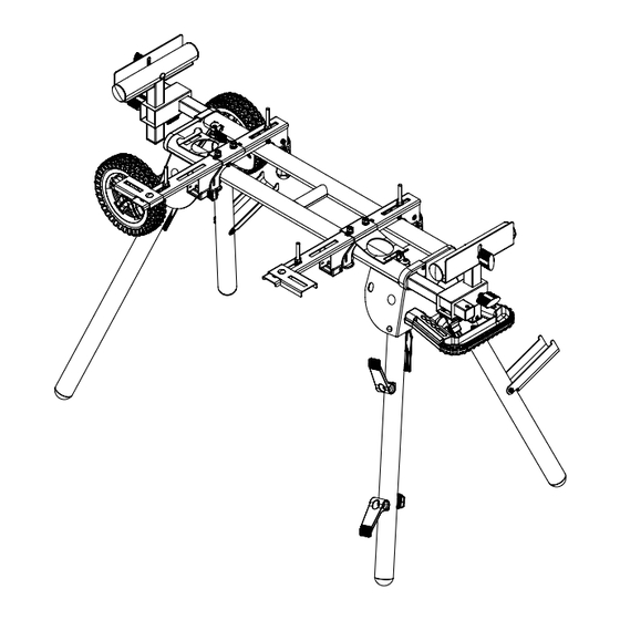
FEATURES Your Miter Saw Stand is loaded with standard features all designed and engineered to maximize the functionality and flexibility of your Miter Saw Stand. STANDARD FEATURES • Rapid Clamp Tool Mounts • Adjustable Material Supports • Wheels for easy transportation OVERVIEW Figure 1 You have just purchased a Miter Saw Stand. -
Page 5: Parts List
PARTS LIST PART # DESCRIPTION PART # DESCRIPTION 1 pc 6 pcs MITER SAW STAND CARRIAGE BOLT M8*20 RAPID CLAMP TOOL MOUNT 2 pcs 12 pcs NUT M8 OFFSET MOUNTING BRACKETS 2 pcs 4 pcs CARRIAGE BOLT M8*60 12 pcs MATERIAL SUPPORT 2 pcs WASHER M8... -
Page 6: Assembly Instructions
ASSEMBLY INSTRUCTIONS Read all assembly instructions completely before attempting assembly. ATTACHING THE WHEELS Figure 2 1. Extend the legs by depressing the leg lock levers. 2. Insert (8) axle through the mounting bracket and make sure the flat of the axle is inserted into the flat of the inside of the mounting bracket. -
Page 7: Attaching The Pull Handle
ASSEMBLY INSTRUCTIONS ATTACHING THE PULL HANDLE Figure 3 1. Place one (18) spring washer and one (17) M8 washer onto (19) M8*20 bolt. 2. Place (19) M8*20 bolt through the back of the holes in the body as shown in Figure 3. 3. -
Page 8: Preparing The Stand
ASSEMBLY INSTRUCTIONS PREPARING THE STAND Figure 4. 1. Grab the (9) handle of the stand so that the wheels are on the ground and supporting the weight of the stand. 2. Press the Quick Release Leg Lock Lever on one of the legs on the side of the handle and rotate the leg downward until the locking pin clicks into place. -
Page 9: Assembling Rapid Clamp Tool Mounts
ASSEMBLY INSTRUCTIONS FIG 5 Work Stop Knob Nut Material Support Receiver Material Support Knob Screw Knob Nut Knob Nut Knob Screw Extension Rail Small Screw Handle Small Screw ASSEMBLING RAPID CLAMP TOOL MOUNTS Figure 6 1. Lay out all parts before starting the assembly process. 2. -
Page 10: Attaching Your Miter Saw Or Other Benchtop Power Tool
ASSEMBLY INSTRUCTIONS 5. Tighten down the (15) M8 nuts that were placed in the rapid clamp tool mounting rail and rapid clamp tool mount base in Step 3. 6. The rapid clamp tool handle and tool storage arms can be placed anywhere along the Rapid Clamp Tool Mounting Rail. -
Page 11: Offset Mounting
ASSEMBLY INSTRUCTIONS 3. Feed one (16) M8*60 carriage bolt up through both the tool mount and a mounting hole in the saw. 4. Secure in place using a (17) flat washer, (18) spring washer, and (15) M8 nut. 5. Repeat through the other end of the tool mount. 6. -
Page 12: Attaching Cord Minder
ASSEMBLY INSTRUCTIONS ATTACHING CORD MINDER Figure 9. 1. Locate leg with 2 pass-through holes. 2. Pass one (23) M5*55 screw through the top hole of the leg and through the (12) plastic cord minder attachment, making sure that the tip of the cord minder attachment is pointing up towards the top of the stand. -
Page 13: To Remove Saw From Stand
ASSEMBLY INSTRUCTIONS FIG 10 J-Lock Clip ™ NOTE: Continue to hold the tool mount assembly with one hand until both levers are securely locked. 6. Check position and adjust if necessary to make sure the weight of the saw is evenly balanced over the rails. -
Page 14: Transporting And Storing
ASSEMBLY INSTRUCTIONS FIG 11 TRANSPORTING AND STORING Figure 12 1. Before storing or transporting, make sure all attachments are secure and bench top tool is removed. 2. Collapse legs and make sure they are locked into the up position. 3. Use the (9) handle that is located on the end of the product for transporting. 4. -
Page 15: Tool Mount Adjustment Screw
ASSEMBLY INSTRUCTIONS TOOL MOUNT ADJUSTMENT SCREW Most plastic tool mounts are designed to fit snugly over the stand rails. With the locking levers in the lowered (locked) position, you should not be able to remove the saw and tool mount assembly from the rails. -
Page 16: Notes
NOTES Page 15... - Page 17 NOTES Page 16...
- Page 18 NOTES Page 17...
-
Page 19: Warranty
MENARDS® retail store. At its discretion, MASTERFORCE® agrees to have the tool or any defective part(s) repaired or replaced with the same or similar MASTERFORCE®... - Page 20 © 2019 Menard, Inc., Eau Claire, WI 54703...
Need help?
Do you have a question about the MASTER-FORCE 240-1657 and is the answer not in the manual?
Questions and answers