Table of Contents
Advertisement
Quick Links
Advertisement
Table of Contents
Troubleshooting

Subscribe to Our Youtube Channel
Summary of Contents for Voith BTG MEK-3000
- Page 1 User Manual MEK-3000 Rotating Consistency Transmitter...
- Page 2 Copyright© 2021 BTG Instruments AB The contents of this document are subject to revision without notice due to continued progress in methodology, design, and manufacturing. BTG shall have no liability for any error or damages of any kind resulting from the use of this document. All rights reserved.
-
Page 3: Table Of Contents
Table of contents Important Information ......1 1 Safety Instructions ....... 3 2 Product Introduction . - Page 4 4 Installation Instructions ......31 Unpacking ..........31 Saddle / Weld-in Stud / Measuring Vessel Installation .
- Page 5 Trouble Shooting ......... . . 85 6.3.1 Calibration Trouble Shooting .
- Page 6 Calibrate Menu ......... . . 113 8.5.1 View Calibration Information .
-
Page 7: Important Information
Important Information Important Information This user manual contains all necessary instructions for installation, operation, maintenance, and basic service of the MEK-3000 NOTE! Always read the safety instructions before installation and service of the Analyzer! The instrument is operated using the CPM communication platform. For guidelines on how to navigate and configure the CPM, see the CPM Operation Guide enclosed as appendix with this manual. - Page 8 Important Information Important Information, MEK-3000 - Rev. A © BTG 2021...
-
Page 9: Safety Instructions
Safety Instructions 1 Safety Instructions General Local Regulations First and foremost National Regulations must be All BTG products are designed according to Sound adhered to followed by any Local Regulations. Engineering Practice and for the Pulp and Paper The National and Local Regulations supersede this Industry. - Page 10 Safety Instructions Safety Regulations Safety Regulations for Installation and Service The symbols below are examples of danger signs found in instructions, manuals, and on products delivered by Always turn off all power and other supplies before BTG. performing any service or maintenance on the product.
-
Page 11: Product Introduction
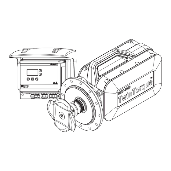
Product Introduction 2 Product Introduction 2.1 General The MEK-3000 TwinTorque takes in-line, rotating, consistency measurement state-of-the-art to a new level. Combining the most robust measuring method with the unique TwinTorque technology results in unrivalled performance in a format providing significantly reduced installation and maintenance costs. The transmitter is supplied by single-phase power via the Communication Platform (CPM). -
Page 12: Technical Data
Product Introduction 2.2 Technical Data General Type MEK-3000 in-line rotating consistency transmitter for pulp suspensions Manufacturer BTG, Säffle, Sweden Measuring Principle Rotating shear force measurement Quality Assurance Quality-assured in accordance with ISO 9001. Designed in accordance with relevant CE standards. Function Specifications General Pressure Rating... - Page 13 Product Introduction Support System Specifications Flushing Water Standard quality water, with no impurities larger than 200 m [8 thou]. Recommended flow: 0.5-1.5 l/min [0.13-0.4 gal/min.] Min. 0.5 bar [7 psi] Power Consumption Max. 320 VA Supply Voltage 100-240 ±10% V AC, 50/60 Hz, Single phase to CPM Supplied with 24 V DC from the CPM Cooling Optional water cooler available for operation in hot environment...
-
Page 14: Type Plate Explanation
Product Introduction 2.3 Type Plate Explanation 2 Type sign Type 12345678 MEK-3000 Wet parts made of Sensing element EN 1.4404/ASTM 316L Pressure rating Propeller Rubber PN 16 EPDM BTG Instruments AB, Industrigatan 1-3, 661 32 Säffle, SWEDEN 1. Transmitter model 2. - Page 15 Product Introduction 10. Propeller type Large, Small, or Hub (no propeller) 11. Rubber quality in wetted parts FPM (Standard) = Fluorocarbon rubber for pH 1-12. EPDM = Ethylene Propylene rubber for pH 8-14. 12. QR code QR code to scan for more information about the MEK-3000 on the site: www.btg.com/mybtg/en/instruments/mek-3000.
-
Page 16: Ce Declaration
Product Introduction 2.4 CE Declaration When using the units in combinations other than those tested for, BTG can not guarantee CE directive conformity. The units in combination with customer-installed external devices may conform with EMC and safety requirements when properly installed and CE-marked equipment is used. -
Page 17: Communication Platform Cpm
Product Introduction 2.5 Communication Platform CPM The CPM is delivered as a complete unit from BTG, normally in conjunction with an instrument. The CPM has the following functions: • Local display and console for full configuration and operation of the instrument •... -
Page 18: Technical Data
Product Introduction 2.5.1 Technical Data General Type CPM Communication Platform. Manufacturer BTG, Säffle, Sweden. Quality Assurance Quality-assured in accordance with ISO 9001. Product Safety Fulfills all relevant CE-directive requirements, RCM listed, and ETL listed. Radio Approvals US, Canada, EU, Japan, Australia, and New Zealand. Emission / Immunity / Safety FCC Part 15 Class B EN 61010-1:2010... - Page 19 Product Introduction FCM-80x0 Fieldbus communication module programmed for PROFIBUS. Equipped with slot for SD memory card. Output / Input signal PROFIBUS (PA) CCM-8200 Network Interfaces: Wired Network Connectivity Ethernet, 10/100 Mbit - RJ45. Ethernet interface supporting up to 100baseTx. IEC 11801:2002 CatV compliant M12 type D socket. The interface supports Auto MDI-X (crossover).
- Page 20 Product Introduction Support System Specifications Supply Voltage Power supply unit 100 - 240 V AC, 50-60 Hz. AC input range: 90 - 264 V continuous operation. Disconnecting Device An external 2-pole switch close to the CPM is required. The switch must be approved in accordance with the IEC 60947-2 and IEC 60947-3 requirements.
-
Page 21: Dimensions
Product Introduction 2.5.2 Dimensions 4 Dimensions .4" 11 2 . " 5 (4x) 0.2" 10 (4x) 0.4" 2" 10" 6" 10.5" 6.5" 8.9" © BTG 2021 Product Introduction, CPM - Rev. C... -
Page 22: Type Plate Explanations
Product Introduction 2.5.3 Type Plate Explanations 5 Type plate BTG Instruments AB Industrigatan 1-3 661 32 Säffle SWEDEN 3068754 R 202-LSF056 PRODUCT SERIAL NUMBER CPM-XX00 123456 TYPE /Q / 0/S / 2 H3/C /R15 RA1/ESPK VOLTAGE FREQUENCY APP. POW CATEGORY FACTORY ID 100-240 V AC 50-60 Hz... - Page 23 Product Introduction 10. Product The instrument model is specified according to the code system explained below: CPM-XX00 Product Group Communication platform Power type 50 W Power supply 240 W Power supply 80 W Power supply Input/Output Unit If field 4 = PH: HCM-8000 If field 4 = PP: FCM-8000 If field 4 = PH: HCM-8010 If field 4 = PP: FCM-8010...
- Page 24 Product Introduction 16. Type specification The instrument variant is specified according to the code system explained below: PH/Q0/M1/S2/H3/C10/RI5/RA1/ESPK Communication Protocol ® Analog 4-20 mA with HART (HCM-80x0) Profibus PA (FCM-80x0) Foundation Fieldbus supplied with FCI-1000 Sensor Control Module No module Sensor control module SCM-8000 Communication Module No module...
-
Page 25: Ce-Declaration
Product Introduction 2.5.4 CE-Declaration When using the units in combinations other than those tested for, BTG can not guarantee CE-directive conformity. The units in combination with customer-installed external devices may conform with EMC and safety requirements when properly installed and CE-marked equipment is used. -
Page 26: Supplier's Declaration Of Conformity
Product Introduction 2.5.5 Supplier's Declaration of Conformity 47 CFR § 2.1077 Compliance Information Unique Identifier: CPM-1300, CPM-1310, CPM-1400, CPM-1410, CPM-1510 Responsible Party - U.S. Contact Information BTG Americas Inc. Instruments (USA) 5085 Avalon Ridge parkway Suite 100 Norcross GA 30071 www.btg.com FCC Compliance Statement This device complies with Part 15 of the FCC Rules. -
Page 27: Installation Planning
Installation Planning 3 Installation Planning 3.1 Process Site Selection for Transmitters Careful siting of the transmitter is essential for optimum performance and ease of maintenance. The transmitter can be installed in a vertical, horizontal or sloping pipe. If installed in a horizontal or sloping pipe, the location should be carefully selected so that air is not trapped into the pipe where the transmitter is installed. -
Page 28: Dilution Water Supply
Installation Planning 3.2 Dilution Water Supply Dilution water must be pressure controlled or otherwise protected from major pressure variations. To ensure good control, dilute no more than 20% in each dilution stage, though a higher percentage may be acceptable early in the process. If considerable dilution is required it should be carried out in two stages, 70% to 80% of the water being added in the bottom part of the pulp chest and the remainder in the form of a fine dilution upstream of the pump. - Page 29 Installation Planning 6 Dilution Water Supply = pressure drop, min. 0.5 bar [7 psi] = Inlet water flow velocity, 3 - 5 m/s [10 - 16.5 ft/s] = Recommended flow velocity L = Recommended calming length G = Water nozzle penetration, min.
-
Page 30: Process Site Selection
Installation Planning 3.3 Process Site Selection The minimum distance the transmitter should be located upstream or downstream of a pump, bend or elbow is the greater of two numbers (see figure 7). Upstream the transmitter, L (consistency < 8%): • 1 m [3 ft] •... - Page 31 Installation Planning 7 Recommended minimum calming length Flow 8 Installation of the transmitter close to a pipe elbow NOTE! Alternative A is the most suitable. Avoid alternative C. © BTG 2021 Installation Planning, MEK-3000 - Rev. B...
-
Page 32: Mek-3000 Dimensions And Mounting
Installation Planning 3.3.1 MEK-3000 Dimensions and Mounting 9 Dimensions and recommended clearances min. 125 5.0" ØD Dimensions Ø180 mm Ø270 mm and weights flange flange 302 mm [12.0"] 283 mm [11.1"] 89 mm [3.5"] 111 mm [4.4"] ØD 180 mm [7.1"] 270 mm [10.6"] Transmitter 15 kg [33 lb]... -
Page 33: Weld-In Saddle
Installation Planning 3.3.2 Weld-in Saddle NOTE! For installation where the pipe diameter is less than 200 mm, the pipe must be coned to a diameter of at least 200 mm before the weld-in saddle can be installed. Saddle can only be used on Ø180 mm flange and in consistency range of 2 - 12% Cs. -
Page 34: Measuring Chamber With Weld-In Stud
Installation Planning 3.3.3 Measuring Chamber with Weld-in Stud NOTE! For installation of small flanges where the pipe diameter is less than 200 mm, the pipe must be coned to a diameter of at least 200 mm before the weld-in stud can be installed. For large flanges the pipe diameter must be at least 300 mm otherwise a measuring vessel should be used. -
Page 35: Sensing Elements
Installation Planning 3.3.5 Sensing Elements Sensing Consistency range Default range values Fiber Feedback element Characteristic type in water type Lower limit Upper limit Lower limit Upper limit Long 0.8% 2.5% 1.00% 2.50% Short 0.8% 2.5% (MEK-3050 only) Sludge 1.5-2% 10-15% Long 1.0% 5.0%... - Page 36 Installation Planning Installation Planning, MEK-3000 - Rev. B © BTG 2021...
-
Page 37: Installation Instructions
Installation Instructions 4 Installation Instructions 4.1 Unpacking 0.25 Flow Unit 1. 1 x Rotating Consistency Transmitter, MEK-3000 2. 1 x Communication Platform, CPM-1400 3. 1 x Dirt Cap 4. 1 x Flushing water connection 5. 1 x Seal water control unit (optional) 6. -
Page 38: Saddle / Weld-In Stud / Measuring Vessel Installation
Installation Instructions 4.2 Saddle / Weld-in Stud / Measuring Vessel Installation 4.2.1 Saddle This side show profils from Ø400 This side show profils from Ø300 DANGER CHECK PIPES! Note! Risk for corrosive, toxic, or aggressive liquids or gases with high pressure or high temperature. - Page 39 Installation Instructions © BTG 2021 Installation Instructions, MEK-3000 - Rev. B...
-
Page 40: Weld-In Stud For Ø180 Mm Flange
Installation Instructions 4.2.2 Weld-in Stud for Ø180 mm Flange NOTE! For installations where the pipe diameter is less than 200 mm, the pipe must be coned to a diameter above 200 mm before the weld-in stud can be installed. DANGER CHECK PIPES! Risk for corrosive, toxic, or aggressive... - Page 41 Installation Instructions MEK-3000 MEK-3015 A = 60 mm (2.4") B = 30 mm (1.2") X = 92 mm (3.6") Y ~ 25 mm (1") 32 mm (1.3") © BTG 2021 Installation Instructions, MEK-3000 - Rev. B...
- Page 42 Installation Instructions B=32 mm (1.3") X=Y=M Installation Instructions, MEK-3000 - Rev. B © BTG 2021...
-
Page 43: Measuring Vessel With Saddle
Installation Instructions 4.2.3 Measuring Vessel with Saddle 4.2.3.1 Flanged-end DANGER CHECK PIPES! Risk for corrosive, toxic, or aggressive liquids or gases 1150 mm with high pressure or (45.3") high temperature. DANGER Use protective clothing A = Left-hand design 1150 45.3" B = Right-hand design ©... - Page 44 Installation Instructions 4.2.3.2 Weld-end DANGER CHECK PIPES! Risk for corrosive, toxic, or aggressive liquids or gases 1150 mm with high pressure or (45.3") high temperature. DANGER Use protective clothing A = Left-hand design B = Right-hand design 1150 45.3" Installation Instructions, MEK-3000 - Rev. B ©...
-
Page 45: Weld-In Stud For Ø270 Mm Flange
Installation Instructions 4.2.4 Weld-in Stud for Ø270 mm Flange NOTE! The M-measurement is measured from the inside of the pipe (step 5 in the figure below). It is determined in advance and may be either 70 or 150 mm (consistency, < 4% = 150, > 4% = 70). DANGER CHECK PIPES! Risk for corrosive,... - Page 46 Installation Instructions B=32 mm (1.3") X=Y=M Installation Instructions, MEK-3000 - Rev. B © BTG 2021...
-
Page 47: Measuring Vessel For Ø270 Mm Flange
Installation Instructions 4.2.5 Measuring Vessel for Ø270 mm Flange 4.2.5.1 Flanged-end DANGER CHECK PIPES! Risk for corrosive, toxic, or aggressive liquids or gases 1150 mm with high pressure or (45.3") high temperature. DANGER Use protective clothing 1150 45.3" A = Left-hand design B = Right-hand design 18.7"... - Page 48 Installation Instructions 4.2.5.2 Weld-end DANGER CHECK PIPES! Risk for corrosive, toxic, or aggressive liquids or gases 1150 mm with high pressure or (45.3") high temperature. DANGER Use protective clothing A = Left-hand design B = Right-hand design 1150 45.3" 18.7" 26.6"...
-
Page 49: Mounting Instructions
Installation Instructions 4.3 Mounting Instructions 4.3.1 Check Mechanical Sealing Movability Tools required: Flat screwdriver, large Consumables required: Water (drinking water quality) Before mounting the transmitter, you must assure that the torque shaft and mechanical seal are not stuck and can be freely turned. Try to turn the torque shaft and mechanical seal by hand according to step 1 below. - Page 50 Installation Instructions NOTE! Step 2 and 3 below should only be performed if the mechanical seal cannot be turned by hand in step 1 above. WARNING Equipment damage WARNING! Be very careful to avoid damaging the mechanical seal ceramics while using the screwdriver.
-
Page 51: Mount The Transmitter
Installation Instructions 4.3.2 Mount the Transmitter Tools required: Block wrench, 13 mm Parts required: Mounting kit NOTE! Tighten the screws to a torque of 17 Nm for M8. With adapter flange (PN25) 11x (D=180 mm) tighten to 33 Nm for M10. 15x ( =270 mm) ©... -
Page 52: Mount / Dismount The Dirt Cap
Installation Instructions 4.3.3 Mount / Dismount the Dirt Cap Mounting Dismounting WARNING Equipment damage NOTE! Be careful when using the screwdriver. Installation Instructions, MEK-3000 - Rev. B © BTG 2021... -
Page 53: Mounting Of Optional Accessories
Installation Instructions 4.4 Mounting of Optional Accessories 4.4.1 Inspection Cover NOTE! Inspection covers can only be installed in pipes with diameter 300 mm. DANGER CHECK PIPES! Risk for corrosive, toxic, or aggressive liquids or gases D= 157 mm with high pressure or (6.2") high temperature. -
Page 54: Connection Instructions
Installation Instructions 4.5 Connection Instructions 4.5.1 Flushing Water Connection NOTE! The flushing water must be of standard quality, with no impurities larger than 200 m [8 thou]. Recommended flow is 0.5-1.5 l/min [0.13-0.4 gal/min]. Min. 0.5 bar [7 psi] Fig 13 Flushing water pipe connection A. - Page 55 Installation Instructions 4.5.1.1 Internal Flow Regulator Connection NOTE! It is recommended to use an external flow regulator for the seal water, see section 4.5.1.2: External Flow Regulator Connection. ° High (> 120 Water flow 0.95 l/min media temp Water coupling with internal flow regulator °...
- Page 56 Installation Instructions 4.5.1.2 External Flow Regulator Connection D = 9 mm Relief valve Min. 0.5 bar (7.5 psi) Opening pressure: 1 bar (15 psi) 0.25 Flow Unit ³ 10 mm Min. 0.5 bar (7.5 psi) To Seal (0.5 - 0.95 L/min Installation Instructions, MEK-3000 - Rev.
-
Page 57: Electrical Connections
Installation Instructions 4.5.2 Electrical Connections 4.5.2.1 Connection of Communication Platform Tools required: Allen key, 3 mm, 4 mm © BTG 2021 Installation Instructions, MEK-3000 - Rev. B... - Page 58 Installation Instructions A B C D Wire Color Function +24 V Black Blue COM- White COM+ Installation Instructions, MEK-3000 - Rev. B © BTG 2021...
-
Page 59: Communication Platform Cpm
Installation Instructions 4.6 Communication Platform CPM 4.6.1 Mounting Instructions Tools required: Screwdriver Drilling machine NOTE! The CPM must be installed in an easily accessible position. Mount the CPM in the selected location by fastening the protective cover to a flat surface. Use four suitable screws. See figure 14 for recommended clearances. -
Page 60: Cabling Instructions
Installation Instructions 4.6.2 Cabling Instructions NOTE! DANGER BTG recommends that separate cables be used for analog and digital signals. Multi conductor cables can be used. Hazardous voltage in the equipment NOTE! Unused cable glands must be sealed in order to fulfill the IP 65 requirement. 4.6.3 Connection Instructions All electrical connections are made inside the CPM. - Page 61 Installation Instructions 4.6.3.1 AC Connection to Power Supply Unit A specific instruction manual for the power supply unit can be found inside the CPM box. DANGER NOTE! Hazardous voltage in the equipment Before installation, ensure that all power to the system has been turned off. Cable connections must be made by authorized personnel.
- Page 62 Installation Instructions 4.6.3.2 HCM Connections ® The Hart communication module (HCM-80xx) is using HART protocol. NOTE! DANGER Before installation, ensure that all power to the system has been turned off. Cable connections must be made by authorized personnel. Hazardous voltage in the equipment NOTE! Figure 16 shows resistance as a function of supply voltage.
- Page 63 Installation Instructions HCM-8000 Connections NOTE! The functions of the connections for each instrument type can be found in the connection tables for HCM-8000 in the appendix of this manual Fig 18 HART Communication Module HCM-8000 Fig 19 Connection of HCM- HCM-8000 +24 V 8000 cable...
- Page 64 Installation Instructions 4.6.3.3 FCM Connections NOTE! DANGER Before installation, ensure that all power to the system has been turned off. Cable connections must be made by authorized personnel. Hazardous voltage in the equipment 1. Insert the signal cables through the cable glands. 2.
- Page 65 Installation Instructions FCM-8000 Connections NOTE! The functions of the connections for each instrument type can be found in the connection tables for FCM-8000 in the appendix of this manual Fig 21 Fieldbus Communication Module FCM-8000 Fig 22 Connection of FCM-8000 FCM-8000 cables Digital Out Digital In 3...
- Page 66 Installation Instructions 4.6.3.4 Communication Module CCM-8200 On CCM-8200 the ethernet interface RJ-45 connector is located at position 1. The USB connector P2 and the connectors P3 - P5 are for future options l Fig 23 Communication Module CCM-8200 1. P1 RJ-45 connector 2.
-
Page 67: Backup Card
Installation Instructions 4.6.4 Backup Card The HCM and FCM modules are equipped with a slot for a memory card of the type Secure Digital (SD). All transmitter settings, transmitter data, and calibration data can be stored on a SD card. The SD card reader is located on the communication module card, and can be accessed by opening the front cover of the CPM (see figure 25). -
Page 68: Connection
Installation Instructions 4.6.5 RS-485 Connection Fig 26 RS-485 connections 1. Software update and temporary communication 2. Primary communication; BTG Software Installation Instructions, CPM - Rev. C © BTG 2021... -
Page 69: Operation Instructions
Operation Instructions 5 Operation Instructions 5.1 Commissioning These steps should be carried out in chronological order to get the transmitter running when put into operation for the first time. The MEK-3000 must be installed in the pipe, and pulp must be admitted to the line, before step 8 and onwards are performed. - Page 70 Operation Instructions 8. Take calibration samples For a basic calibration, with pre-defined calibration constants, a single sample is required to check if there is a need of an offset adjustment. For a lab calibration, a single sample can be used to get started quickly and obtain a correct calibration at the present consistency level, but for a more exact calibration, multiple samples at various consistency levels are required.
- Page 71 Operation Instructions 11. Configure alarm and warning settings All available alarm and warning functions are described in . Configure the alarms and warnings according to your requirements. For guidelines, see section 8.7.2: Configure Alarm Settings and section 8.7.3: Configure Warning Settings. 12.
- Page 72 Operation Instructions Operating Instructions, MEK-3000 - Rev. A © BTG 2021...
-
Page 73: Service Instructions
Service Instructions 6 Service Instructions 6.1 Maintenance Recommendations 6.1.1 Regular Maintenance of the Transmitter Maintenance needs will depend on the transmitter position, media influence, and ambient conditions. Regular maintenance includes: • Weekly inspection of flushing water and possible leakage. • Semi-annual inspection of wetted rubber details and metal parts for damage, if exposed to aggressive chemicals. -
Page 74: Service Actions
Service Instructions 6.2 Service Actions 6.2.1 Removing the Transmitter from the Pipe Tools required: Block wrench, 13 mm Allen key, 3 mm, 4 mm NOTE! While performing step 3, check the condition of the O-ring in the cable gland holder. If defect, change the O-ring. -
Page 75: Changing O-Rings And Sealings
Service Instructions 6.2.2 Changing O-rings and Sealings Parts required: Sealing Kit (see spare part list) All O-rings and sealings that need to be changed on a regular basis are collected in a service kit as shown in figure 27 below. A Secondary Sealing Kit, containing only the Secondary sealing (5) and spiral retaining ring (4), is also available. -
Page 76: Changing The Electronics Card
Service Instructions 6.2.3 Changing the Electronics Card Parts required: Electronics Card kit (see spare part list) A service kit for changing the electronics card is available. The included parts are shown in figure 28 below. Instructions for changing the electronics card are available in a separate service kit manual, which in included in the Electronics card kit. -
Page 77: Changing Sensing Element And Propeller/Hub
Service Instructions 6.2.4 Changing Sensing Element and Propeller/ For instructions on how to remove and mount the sensing element and the propeller/hub, see appropriate steps in section 6.2.5: Changing the Flange. NOTE! After the sensing element and propeller/hub have been changed, the sensing element type, sensing element number, and propeller number must be updated in the CPM. -
Page 78: Changing The Flange
Service Instructions 6.2.5 Changing the Flange NOTE! The instructions in this section show how to change from a Ø180 to a Ø270 mm flange, but are also valid when changing from a Ø270 to a Ø180 mm flange as well. 6.2.5.1 Reading the Feedb (Feed Back) value (serial number <... - Page 79 Service Instructions Reading the Feedb value 1. Let the transmitter run for approximately 10 minutes. NOTE! The transmitter should not be run unattended. Add water in the Flushing water chamber if the water level sinks. 2. Press “F3” twice on the CPM to get to the “Raw values” menu. Read the Feedb value and note it for later use, when assembling the flange.
- Page 80 Service Instructions NOTE! Remove the O-ring carefully, to prevent the Feedb value to change. Service Instructions, MEK-3000 - Rev. B © BTG 2021...
- Page 81 Service Instructions 6.2.5.3 Removing the Mechanical and Secondary Sealings This instruction is only applicable if the sealings from the old flange are to be re-used with the new flange. The sealings can only be re-used if they never have been used in operation. NOTE! Never re-use a mechanical sealing that previously has been in operation.
- Page 82 Service Instructions 6.2.5.4 Mounting the Flange Tools required: Allen key, 2,5 mm, 5mm Block wrench, 16 mm Consumables required: Soap water (SW), Light machine oil NOTE! In step 1, make sure that the rubber follows the mechanical sealing and is not twisted. NOTE! In step 2, make sure that the rubber follows the secondary...
- Page 83 Service Instructions NOTE! In step 5, press the mechanical seal past the groove in the shaft for the spiral retaining ring. NOTE! In step 8, make sure that the mechanical sealing slips back against the spiral retaining ring. © BTG 2021 Service Instructions, MEK-3000 - Rev.
- Page 84 Service Instructions NOTE! In step 10, tighten each screw one turn at a time until all screws are fully tightened. NOTE! In step 11, see section 6.2.5.5 on page 79 or section 6.2.5.6 on page 82 WARNING Equipment damage WARNING! Hold the sensing element only, not the hub or propeller, while tightening the screw.
- Page 85 Service Instructions 6.2.5.5 Adjusting the Angle Setpoint (Serial number < 44800000) An angle setpoint adjustments must be carried out before the transmitter can be re-installed and put back into operation. See the CPM Operation Guide, included with this manual, for additional instructions on how to access the parameters mentioned below.
- Page 86 Service Instructions Read and compare Feedb values 1. Press “F3” twice on the CPM to get to the “Raw values” menu. Read the Feedb (Feed Back) value. 2. Compare this Feedb value with the Feedb value noted in section 6.2.5.1 on page 72.
- Page 87 Service Instructions Read and compare new Feedb value 1. Press “F3” twice on the CPM to get to the “Raw values” menu. Read the Feedb (Feed Back) value. 2. Compare this Feedb value with the Feedb value noted in section section 6.2.5.1 on page 72.
- Page 88 Service Instructions 6.2.5.6 Adjusting the Angle Setpoint (Serial number > 44800000) An angle setpoint adjustments must be carried out before the transmitter can be re-installed and put back into operation. See the CPM Operation Guide, included with this manual, for additional instructions on how to access the parameters mentioned below.
- Page 89 Service Instructions Read and compare Feedb values 1. Start the transmitter. 2. Press “F3” twice on the CPM to get to the “Raw values” menu. Read the Feedb value. 3. Compare this Feedb value with the Feedb value noted in Preparations. 4.
- Page 90 Service Instructions Read and compare new Feedb value 1. Start the transmitter, when necessary. 2. Press “F3” twice on the CPM to get to the “Raw values” menu. Read the Feedb value. 3. Compare this Feedb value with the Feedb value noted in section Preparations.
-
Page 91: Trouble Shooting
Service Instructions 6.3 Trouble Shooting Symptom Probable Cause Solution 1. No or erroneous signal 1.1. Basic check Make sure that the process is working as usual and pulp is flowing in the pipe. Make sure that power is supplied to the communication platform. - Page 92 Service Instructions Symptom Probable Cause Solution 2. Output signal varies with 2.1. The transmitter is not mounted Check the installation with reference to the changes in flow according to instructions. It may Installation Engineering Guide. Note the be installed at a point where the length of the turbulence damping zone after pulp suspension is layered, and the pump and check that the length of the...
- Page 93 Service Instructions Symptom Probable Cause Solution 9. Mechanical seal: Irregular 9.1. The seat is not aligned Change the mechanical seal. See section wear marks on seat rings 6.2.2 on page 69 10. Mechanical seal leaks 10.1. Sealing surfaces damaged due Change the mechanical seal.See section to dry running.
-
Page 94: Calibration Trouble Shooting
Service Instructions 6.3.1 Calibration Trouble Shooting Typical errors in single point calibration Symptom Probable Cause Solution 1. Calibration lacks precision 1.1. Sample 1 (Feedback in water) Activate sample 1 and perform a new lab is not activated. The calibration calibration. For instructions, see the CPM line is drawn between 0% FB Operation Guide, included with this manual. -
Page 95: Appendix
Appendix 7 Appendix 7.1 HCM-8000 Connections Connection Block Function Digital In 3 Sample Input or Interlock Digital Out Alarm Output Digital In 1 Calibration set Input A Digital In 2 Calibration set Input B Analog Out Consistency output value, 4 - 20 mA Analog In Not used Calibration Set configuration... -
Page 96: Fcm-8000 Connections
Appendix 7.2 FCM-8000 Connections Connection Block Function Digital Out Alarm Output Digital In 3 Sample Input or Interlock See separate table below for data FF / PROFIBUS PA between Profibus and Transmitter Data Between Profibus and transmitter Profi-bus Transmitter Function Consistency output Not used Not used... -
Page 97: Alarms And Warnings
Appendix 7.3 Alarms and Warnings The following alarms and warnings are available for MEK-3000, and are accessed and configured from the CPM. Guidelines on how to access and configure the alarm and warning settings can be found in section 8.7.2: Configure Alarm Settings and section 8.7.3: Configure Warning Settings All alarms and warnings are by default activated. -
Page 98: Raw Values
Appendix 7.4 Raw Values The following raw values are available for MEK-3000 on the CPM. Guidelines on how to access the raw values can be found in section 8.4.2: View Instrument Information Parameter Description Temp.PCB The electronics card temperature Speed The motor speed AngErrStDv The angle difference value, that is, the actual value of... -
Page 99: Life Cycle Diagnostics
Appendix 7.5 Life Cycle Diagnostics The following life cycle diagnostics are available for MEK-3000 on the CPM. Guidelines on how to access the diagnostics can be found in section 8.7.1: Life Cycle Diagnostics Parameter Description CalibSetChanges The number of times the active calibration set has been changed through the digital inputs. -
Page 100: Pulp Types
Appendix 7.6 Pulp Types Pre-defined calibrations are available for the pulp types specified in the table below. Guidelines on how to set/change pulp type can be found in section 8.5.3: Basic Calibration Pulp type Explanation CTMP Chemi-ThermoMechanical pulp Ground Wood HardWood Bleached HardWood Unbleached Old Corrugated Container... -
Page 101: Mek-3000 Documentation Form
Appendix 7.7 MEK-3000 Documentation Form Instrument ID/Tag: ..........Serial No.: ............Date:..............Signature:............Calibration Set Set 1 Set 2 Set 3 Set 4 Quality/Pulp: Measurement/Sample Menu - View/Edit Basic Settings (See section 8.4.3 on page 109) Damping Offset Lower measuring range value (LRV) Upper measuring range value (URV) Calibrate Menu - Basic Calibration (See section 8.5.3 on page 115) Configure Menu - Sensor Configuration (See section 8.6.3 on page 124) - Page 102 Appendix Appendix, MEK-3000 - Rev. A © BTG 2021...
-
Page 103: Cpm Operation Guide
CPM Operation Guide CPM Operation Guide Introduction The CPM communication platform is delivered as a complete unit from BTG, normally in conjunction with an instrument. The CPM is a control panel for complete configuration and operation of the instrument. 8.1.1 Software Versions All instructions and display view images in this guide are based on the software versions specified in the tables below. -
Page 104: How To Read This Guide
CPM Operation Guide 8.1.3 How to Read This Guide This guide is a reference manual for all operation actions that can be performed using the CPM Communication Platform. The operations described in this guide are general for all CPM based instruments. -
Page 105: Menu Structure Overview
CPM Operation Guide Menu Structure Overview The menu structure of the CPM is based on a main menu with five sub-menus. All instrument operations are performed from any of the sub-menus. Main Menu Fig 39 Menu structure MEK-3000 XXX-8000 overview X.XX/X.XX X.XX Measurement... -
Page 106: Measurement/Sample Menu
CPM Operation Guide 8.2.1 Measurement/Sample Menu CPM Operation Guide, Menu Structure Overview - Rev. A © BTG 2021... -
Page 107: Calibrate Menu
CPM Operation Guide 8.2.2 Calibrate Menu © BTG 2021 CPM Operation Guide, Menu Structure Overview - Rev. A... -
Page 108: Configure Menu
CPM Operation Guide 8.2.3 Configure Menu CPM Operation Guide, Menu Structure Overview - Rev. A © BTG 2021... -
Page 109: Diagnostics Menu
CPM Operation Guide 8.2.4 Diagnostics Menu © BTG 2021 CPM Operation Guide, Menu Structure Overview - Rev. A... -
Page 110: Backup Menu
CPM Operation Guide 8.2.5 Backup Menu CPM Operation Guide, Menu Structure Overview - Rev. A © BTG 2021... -
Page 111: General Operation
CPM Operation Guide General Operation 8.3.1 Indicators A thin column at the rightmost section of the display is reserved for indicators of various kind. The indicators that can appear in this area are shown and explained below. 1. Indicator column MEK-3000 Calib set(1) Channel 2. -
Page 112: Calibration Set
CPM Operation Guide Indicator Description Lock indicator The lock indicator appears when the system is locked for editing, which means that no settings can be changed. For more information on how to lock/unlock the system, see section 8.6.1: General Configuration. Logging indicator / The logging indicator appears as a blinking letter ‘C’... -
Page 113: Channels
CPM Operation Guide 8.3.3 Channels Some instruments can provide multiple types of measurement results, and this is handled by using separate channels. Each channel has its own configuration and is calibrated separately, but calibration samples are always taken for all channels at once. Measuring results, calibration data, and instrument settings are always displayed for the active channel only. -
Page 114: Measurement/Sample Menu
CPM Operation Guide Measurement/Sample Menu 8.4.1 View Device Status The status view shows any active alarms, warnings, or system status messages. An active alarm is indicated in the Measurement/Sample menu by the letter “A” blinking in the upper right corner of the display. -
Page 115: View/Edit Basic Settings
CPM Operation Guide 8.4.3 View/Edit Basic Settings The most basic instrument settings are available from the Basic settings view, which is quickly and easily accessed from the Measurement/sample menu. All basic settings can also be accessed from the Configure menu. See section 8.6: Configure Menu. 8.4.3.1 Basic Settings for HCM-8000 All displayed values and all changes made in the Basic settings view are valid for the active calibration... - Page 116 CPM Operation Guide 8.4.3.2 Basic settings for FCM-8000 Measurement/ Status Instrument information sample menu MEK-3000 Calib set(1) RawValue XX 12.3456 Channel 3.12 Menu Sample Next Back Sample Next Back Next Basic settings Damping 0 Sec Offset 0.00 %Cs Value 3.12 %Cs 123456789012 345678901234 Edit damping value...
-
Page 117: Take Sample
CPM Operation Guide 8.4.4 Take Sample Calibration samples are taken directly from the Measurement/Sample menu, or from the Instrument information view. Samples are saved for all channels at once, but only for the presently active calibration set. While taking samples, collect pulp samples from the line for lab evaluation at the same time. Mark each pulp sample with sample number, sample date, and sample time. - Page 118 CPM Operation Guide 8.4.4.1 Sample Table Full If the sample table is full (i.e. no more samples can be saved), a warning will be displayed, and you will be given the option to delete one sample. Should you decide not to delete any sample, you can still proceed with the sampling procedure and present the sample result, but you will not be able to save the sample.
-
Page 119: Calibrate Menu
CPM Operation Guide Calibrate Menu 8.5.1 View Calibration Information The Calibration info view shows various information about the present calibration. Measurement/ sample menu Main Menu Calibrate menu MEK-3000 Calib set(1) MEK-3000 XXX-8000 Calib set Channel X.XX/X.XX X.XX Channel 3.12 Cal type: General Measurement... -
Page 120: View Correlation Graph
CPM Operation Guide 8.5.2 View Correlation Graph The correlation graph provides a graphical view of how well the calculated sample values correlate to their lab values. Only samples with a lab value assigned are shown in the graph. Activated samples are designated by a “+”... -
Page 121: Basic Calibration
CPM Operation Guide 8.5.3 Basic Calibration A basic calibration is a simplified calibration method, using pre-defined calibration constants. It is performed either by selecting pre-defined calibration constants for a specific pulp type, or by manually entering the calibration constants if these are known. Measurement/ sample menu Main Menu... -
Page 122: Lab Calibration
CPM Operation Guide 8.5.4 Lab Calibration A lab calibration is based on a number of sample values and their corresponding lab values. The number of samples needed for a calibration depends on the instrument type and the process conditions. Very large variations in pulp/stock compositions can be handled by using separate calibration sets. - Page 123 CPM Operation Guide Measurement/ sample menu Main Menu Calibrate menu Calib set MEK-3000 Calib set(1) MEK-3000 XXX-8000 Channel Channel X.XX/X.XX X.XX 3.12 Cal type: General Measurement... Calibrate... Calibration info... Configure... Basic Calibration... Diagnostics... Backup... Lab calibration... Menu Enter Edit Menu Sample Next Enter...
- Page 124 CPM Operation Guide 8.5.4.2 Perform Lab Calibration The procedure to perform a lab calibration is shown in the image below. Only activated samples (indicated by an asterisk, see section 8.5.4.1: Sample Management) will be included in the calibration. Measurement/ sample menu Main Menu Calibrate menu MEK-3000 Calib set(1)
-
Page 125: Configure Menu
CPM Operation Guide Configure Menu 8.6.1 General Configuration Measurement/ Main Menu Configure menu sample menu MEK-3000 Calib set(1) MEK-3000 XXX-8000 Calib set Channel X.XX/X.XX X.XX Channel 3.12 Measurement... Calibrate... General config... Configure... Sensor config... Diagnostics... Output config... Backup... Menu Sample Next Enter Menu... - Page 126 CPM Operation Guide The input parameters for general configuration are as follows: Parameter Description Explanation Damping A damping constant that can A higher damping value will increase the be set after calibration to damping of the signal. The unit and valid range of stabilize the signal the damping constant depends on the instrument.
-
Page 127: Output Configuration
CPM Operation Guide 8.6.2 Output Configuration 8.6.2.1 Output configuration for the HART Communication Module, HCM-8000: Measurement/ Configure menu sample menu Main Menu MEK-3000 Calib set(1) MEK-3000 XXX-8000 Calib set Channel X.XX/X.XX X.XX Channel 3.12 Measurement... Calibrate... General config... Configure... Sensor config... Diagnostics... - Page 128 CPM Operation Guide Parameter Description Explanation Alarm mA Defines the behavior of the The following alarm modes are available: analog 4-20 mA output signal High: Sets and locks the analog output signal when an alarm is activated to approximately 22.5 mA Low: Sets and locks the analog output signal to approximately 3.3 mA...
- Page 129 CPM Operation Guide 8.6.2.2 Output configuration for the Fieldbus Communication Module, FCM-8000 Measurement/ Configure menu sample menu Main Menu MEK-3000 Calib set(1) MEK-3000 XXX-8000 Calib set Channel X.XX/X.XX X.XX Channel 3.12 Measurement... Calibrate... General config... Configure... Sensor config... Diagnostics... Output config... Backup...
-
Page 130: Sensor Configuration
CPM Operation Guide 8.6.3 Sensor Configuration Sensor configuration for the MEK-3000. Most sensor configuration parameters are factory preset and should normally not be changed unless they have been reset and needs to be recovered, or if the sensing element, propeller, or electronics card are changed. Measurement/ sample menu Main Menu... - Page 131 CPM Operation Guide Measurement/ Main Menu Configure menu sample menu MEK-3000 XXX-8000 MEK-3000 Calib set(1) Calib set Channel vX.XX/XX vX.XXvX.XX Channel 3.12 Measurement... Calibrate... General config... Configure... Sensor config... Diagnostics... Output config... Backup... Enter Menu Enter Edit Menu Sample Next Sensor configuration Sensor type IntrlOffDelay...
- Page 132 CPM Operation Guide The input parameters for Sensor configuration are as follows Parameter Description Explanation Sensor type The MEK-3000 sensing Factory preset value. element type. If the sensing element type is changed, the new type must be specified here. Note that changing this setting affects the output measuring range settings, and the water value sample.
- Page 133 CPM Operation Guide Parameter Description Explanation Interlock Manual interlock function. If the function of digital input 3 (see parameter DI3 Function above) is set to interlock, this parameter works a read-only indicator of the interlock status. Otherwise, this parameter can be used to manually activate the interlock function, that is, turn of the motors.
- Page 134 CPM Operation Guide Parameter Description Explanation Mode Available modes for 0: Cog space mode - Shows the cog space value advanced transmitter between the two cog wheels. adjustments. 1: Run mode - Normal operation. 3: Angle Setpoint mode - Automatic adjustment of the AngleSetpoint parameter value.
-
Page 135: Diagnostics Menu
CPM Operation Guide Diagnostics Menu 8.7.1 Life Cycle Diagnostics Measurement/ sample menu Main Menu Diagnostics menu Calib set MEK-3000 Calib set(1) MEK-3000 XXX-8000 X.XX/X.XX X.XX Channel Channel 3.12 Measurement... Calibrate... Life cycle diag... Configure... Alarm settings... Diagnostics... Warning settings... Backup... Event log... -
Page 136: Configure Alarm Settings
CPM Operation Guide 8.7.2 Configure Alarm Settings Configuration of the instrument’s alarm functions is performed from the Alarm settings view. The available alarm functions are specific for each instrument type, but most alarms have configurable upper and lower alarm limits, and can be turned on/off. An active alarm is indicated in the Measurement/Sample menu by the letter “A”... -
Page 137: Configure Warning Settings
CPM Operation Guide 8.7.3 Configure Warning Settings Configuration of the instrument’s warning functions is performed from the Warning settings view. The available warning functions are specific for each instrument type, but most warnings have configurable upper and lower alarm limits, and can be turned on/off. Unlike for alarms, there is no indicator that shows that a warning is active. -
Page 138: View Event Log
CPM Operation Guide 8.7.4 View Event Log All events, such as system start-up, activation and deactivation of alarms and warnings, etc. are stored in the event log. Each event can be displayed with date and time in the Event log view. Measurement/ Main Menu Diagnostics menu... -
Page 139: Backup Menu
CPM Operation Guide Backup Menu 8.8.1 Store Data on a Memory Card All instrument settings, instrument data, and calibration data can be stored on a memory card of the type Secure Digital (SD/SDHC/SDXC). The SD card reader is located on the communication module card, and can be accessed by opening the front cover of the CPM. -
Page 140: Restore Data From A Memory Card
CPM Operation Guide 8.8.2 Restore Data from a Memory Card All available backup folders on a memory card are shown when entering the Restore view. If there are more than six folders on a card, the view can be scrolled using the scroll keys. The folders for communication module data, and for sensor and calibration data must be restored separately. -
Page 141: Format Memory Card
CPM Operation Guide 8.8.3 Format Memory Card Memory cards of the type SDHC and SDXC can be formatted for backup usage directly from the CPM via the Format view. Regular SD cards must be formatted to the file format FAT16 from a PC. When the Format view is accessed, and a valid SDHC/SDXC card is detected, a warning message will appear. -
Page 142: Store Data And Log Tables On Memory Card
CPM Operation Guide 8.8.4 Store Data and Log Tables on Memory Card Initially, the Backup & Log view looks exactly the same as the Backup view, and the backup process is performed in the same way as described in section 8.8.1: Store Data on a Memory Card. However, when the backup is finished, logging of tables is automatically initiated. -
Page 143: Configure Logging Update Rate
CPM Operation Guide 8.8.5 Configure Logging Update Rate The Update Rate view contains a single parameter (UpdateRate), which specifies how often the instrument is allowed to buffer results for retrieval by BTG-Log, BTG Software, and CPM SD card logging. If set to 0, there is no time limitation and all results from the instrument will be buffered. For instruments which produces multiple results per second, SD card logging can never catch up with an update rate set to 0 s and is on the limit with 1 s, but copes well with 2 s. - Page 144 CPM Operation Guide CPM Operation Guide, Backup Menu - Rev. A © BTG 2021...
-
Page 145: Parts List
Parts List 9 Parts List 9.1 Spare Parts Rec. Item spare Service Kit Part No. Description parts HB0021600 Mech. sealing: Metal bellow, SS/FPM HB0021618 Mech. sealing: Metal bellow, SS/EPDM HB0103275 Mech. sealing: Metal bellow, SMO/FPM Sealing kit HB0021626 Mech. sealing: Roplan Type, SS/FPM HB0021634 Mech. -
Page 146: Accessories
Parts List 9.2 Accessories 0.25 Flow Unit Rec. Item spare Service Kit Part No. Description parts Seal water control unit P35011089 Relief valve P35011238 Cooling kit HB0021717 HB0021881 PN16 Adapter flange HB0101717 PN16, 254 SMO HB0101683 PN25 Adapter flange with protector FB0101691 PN25 Connection plug... -
Page 147: Sensing Elements
Parts List 9.3 Sensing Elements Basic Characteristic Part No Material Type shape/diam. P73198806 EN 1.4404 PA0004879 254 SMO P73198814 EN 1.4404 PA0004887 254 SMO P73198822 EN 1.4404 PA0004895 254 SMO 4.7" P74359761 EN 1.4404 PA0006338 254 SMO 6 " P74359779 EN 1.4404 HA0006346 254 SMO... -
Page 148: Propellers
Parts List 9.4 Propellers Basic Characteristic Part No Material Type shape/diam. PA0113936 EN 1.4404 Large PA0119271 254 SMO 8.0" PA0119370 EN 1.4404 Small PA0119289 254 SMO 5.1" PA0102335 EN 1.4404 PB0021501 254 SMO 9.5 Flanges Basic Characteristic Part No Material Type shape/diam. -
Page 149: Cpm
Parts List 9.6 CPM Most CPM spare parts are delivered in kits. Each kit includes instructions. 9.6.1 CPM-1400 with HCM/FCM-8000 Rec. spare Spare Part Part No. Description parts Without electronics Including: Console kit large PB2000196 Protective cover, Display holder, Front tape, Attachments Display card kit PB0011049... - Page 150 Parts List Rec. spare Spare Part Part No. Description parts Hart communication module Including: HCM-8000 kit PB0011015 Bottom socket, Contact for transmitter (5 pin) Fieldbus communication module, programmed for PROFIBUS (PA) FCM-8000 kit PB0011551 Including: Bottom socket, Contact for transmitter (5 pin). Interlock relay Kit PA0119867 Alarm relay Kit...
-
Page 151: Cpm Accessories
Parts List 9.6.2 CPM Accessories Rec. spare Spare Part Part No. Description parts Communication cable RS-485 HA0112953 © BTG 2021 Parts List, CPM - Rev. B... - Page 152 Parts List Parts List, CPM - Rev. B © BTG 2021...
- Page 153 BTG Instruments AB P.O. Box 602 SE-661 29 Säffle Sweden Phone: +46 533 426 00 www.btg.com...
Need help?
Do you have a question about the BTG MEK-3000 and is the answer not in the manual?
Questions and answers