Table of Contents
Advertisement
Advertisement
Table of Contents

Related Manuals for Dahua VTO3211D-P2


Summary of Contents for Dahua VTO3211D-P2
- Page 1 Villa Door Station (Version 4.3) Quick Start Guide V1.0.1...
- Page 2 Foreword General This manual introduces the installation, functions and operations of the Villa door station (hereinafter referred to as "the Device"). Read carefully before using the device, and keep the manual safe for future reference. Safety Instructions The following categorized signal words with defined meaning might appear in the manual. Signal Words Meaning Indicates a medium or low potential hazard which, if not avoided, could result...
- Page 3 All designs and software are subject to change without prior written notice. Product updates might result in some differences appearing between the actual product and the manual. Please contact customer service for the latest program and supplementary documentation. There might be errors in the print or deviations in the description of the functions, operations ...
-
Page 4: Important Safeguards And Warnings
Important Safeguards and Warnings This section introduces content covering the proper handling of the device, hazard prevention, and prevention of property damage. Read carefully before using the device, and comply with the guidelines when using it. Operation Requirements ● Check whether the power supply is correct before use. ●... -
Page 5: Table Of Contents
Table of Contents Foreword ................................I Important Safeguards and Warnings ......................III 1 Network Diagram ............................1 2 Appearance ..............................2 VTO2101E-P ....................................2 2.1.1 Front Panel ..................................2 2.1.2 Rear Panel ..................................3 VTO3211D-P ....................................3 2.2.1 Front Panel ..................................3 2.2.2 Rear Panel .................................. -
Page 6: Network Diagram
Network Diagram The devices used in the network diagram are for reference only. -
Page 7: Appearance
Appearance VTO2101E-P 2.1.1 Front Panel VTO2101E-P Table 2-1 Front panel description Name Description Inputs audio. Camera Monitors doorway area. IR illunimation light Provides extra IR light for the camera when it is dark. Light sensor Detects ambient lighting condition. Call button Press the button to call VTH or the management center. -
Page 8: Rear Panel
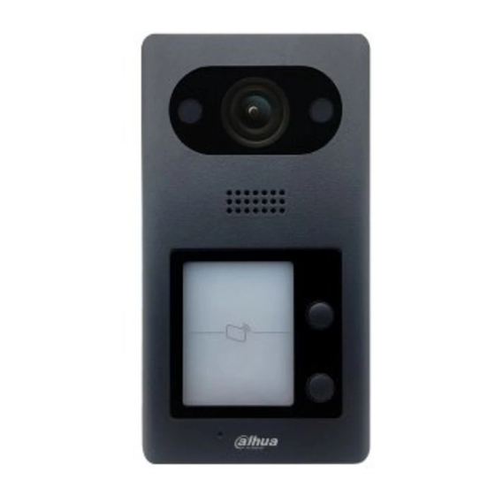
Table 2-3 Port description DOOR POWER/485 Name Name +12V RS-485A ALARM IN RS-485B VTO3211D-P 2.2.1 Front Panel Number of buttons on the front panel varies on different models. VTO3211D-P2 has two buttons; VTO3211D-P4 has four buttons. VTO3211D-P4 will be taken as an example. -
Page 9: Rear Panel
VTO3211D-P Table 2-4 Front panel description Name Description IR illumination light Provides extra IR light for the camera when it is dark. Camera Monitors doorway area. Speaker Outputs audio. Call button Press the button to call VTH or the management center. Inputs audio. - Page 10 Table 2-5 Rear panel description Name Description Cable ports See Figure 2-6 and Table 2-6. Cable tray You can thread the cable through the cable tray. Cable connection Table 2-6 Cable port description Name Name ALM_COM DOOR_FEED ALM_NO DOOR_NC ALM_IN DOOR_COM RS485B DOOR_NO...
-
Page 11: Vto2211G/Vto1201G
VTO2211G/VTO1201G 2.3.1 Front Panel Front panel of VTO2211G/VTO1201G Table 2-7 Front panel description Description Camera Press the button to call an indoor monitor VTH or the management center. Indicator light. Off: The device in standby mode; Solid green: VTO making a call; Solid blue: VTO during a call;... -
Page 12: Rear Panel
2.3.2 Rear Panel Rear panel of VTO2211G/VTO1201G Table 2-8 Rear panel description Description Description Network port Ports SD card cover Tamper button VTO2211G cable connection... - Page 13 Table 2-9 Port description Name Name Alarm input device DOOR1_NC Alarm output device Not available DC_IN- DOOR1_COM DC_IN+ Not available ALARM_IN DOOR1_NO +12V_OUT Not available Not available ALARM_NO DOOR1_FB RS485B Not available ALARM_COM RS485A Not available Not available DOOR1_PUSH VTO1201G cable connection Table 2-10 Port description Name DC_IN-...
- Page 14 Name Name Not available ALARM_NO DOOR1_FB RS485B Not available ALARM_COM RS485A Not available Not available DOOR1_PUSH DOOR1_NC Magnetic lock Not available Electric lock...
-
Page 15: Installation
Installation Notice Do not install the VTO at places with condensation, high temperature, grease or dust, chemical corrosion, direct sunlight, or zero shelter. The installation and adjustment must be finished by professionals, and do not disassemble the VTO. Guidance See Figure 3-1 the installation position. -
Page 16: Configuration
Configuration This chapter introduces how to initialize, connect, and make primary configurations to VTOs and VTHs to realize basic functions, including device management, calling, and monitoring. For details, see the user manual. Configuration Process Before configuration, check each device and make sure there is no short circuit or open circuit. Plan IP address for each device, and also plan the apartment number and room number you need. -
Page 17: Configuring Vto Number
Device initialization Enter and confirm the password, and then click Next. The email setting interface is displayed. Select the Email check box, and then enter your Email address. This Email address can be used to reset the password, and it is recommended to finish this setting. Click Next. -
Page 18: Configuring Network Parameters
Main interface Select Local Setting > Basic. Device properties In the No. input box, enter the VTO number you planned for the VTO you are operating, and then click Confirm to save. 4.3.3 Configuring Network Parameters Select Network Setting > Basic. TCP/IP information Enter the network parameters you planed, and then click Save. -
Page 19: Configuring Sip Server
4.3.4 Configuring SIP Server The SIP server is required in the network to transmit intercom protocol, and then all the VTO and VTH connected to the same SIP server can make video calls among each other. You can use VTOs or other servers as SIP server. -
Page 20: Configuring Call No. And Group Call
4.3.5 Configuring Call No. and Group Call You need to configure call No. on each VTO, and then all the VTOs can call the defined room when you press the call button. On the SIP server, you can enable group call function, and when calling a main VTH, the extension VTHs will receive the call as well. -
Page 21: Adding Room Number
Click Add. Add VTOs Configure the parameters, and be sure to add the SIP server itself too. Table 4-2 Add VTOs Parameter Description The VTO number you configured for the target VTO. See the details in Rec No. "4.3.2 Configuring VTO Number." Register Password Keep default value. - Page 22 Room No. Management Click Add. Add single room number Configure room information. Table 4-3 Room information Parameter Description First Name Last Name Enter the information you need to differentiate each room. Nick Name Room No. The room number you planned.
-
Page 23: Verifying Configuration
Parameter Description First Name Last Name Enter the information you need to differentiate each room. Nick Name If you use multiple VTHs, the room number of the main VTH should be "room number#0", and the room number of the extension VTH should be "room number#1", "room number#2", and so on. - Page 24 Door Select a VTO to watch monitoring videos. Watching monitoring videos...
-
Page 25: App Installation And Adding Device
App Installation and Adding Device Scan the following QR code to download and install the app. Before adding the VTO to the DMSS Plus, you need to modify IP address of the VTO, make sure that the VTO and the router are connected to the same network, and connect the VTO to the power source. - Page 26 Home on the Home interface. on the upper-right corner of the Device Manager interface. Device manager...
-
Page 27: Adding Through Wired Network
Adding through Wired Network Tap IP/Domain on Figure 5-3. Add device Tap VTO on the Add Device interface. Add device Enter Address (IP address of the VTO), Device Name, and Device Password. The VTO is added. You can watch videos captured by the VTO, call the VTO, unlock doors when there is call from the VTO, and more. -
Page 28: Adding Through Soft Access Point (Ap)
Door Adding through Soft Access Point (AP) Connect the door station to the power source. Go to the WLAN interface of your mobile phone. Press and hold the call button on the door station for over 5 seconds until you hear a beep. Connect your phone to the VTO2211G-WP_b67356.. - Page 29 Mobile phone WLAN on the upper right corner of the Device Manager interface (see Figure 5-3). Tap SN/Scan on Figure 5-3.
- Page 30 Scan the QR code Scan the QR code at the rear cover of the door station. The QR code can also be found in Network > Basic > P2P on the web interface, Tap Next.
- Page 31 Add device on the upper-right corner.
- Page 32 Select network configuration mode Select Switch to AP Configuration. Tap Next. Set phone network Tap Set.
- Page 33 Select a Wi-Fi Tap a Wi-Fi name. Enter Wi-Fi password Enter the Wi-Fi password. Tap Next.
- Page 34 Add device Enter device name and device password (door station web login password). The VTO is added. You can watch videos captured by the VTO, call the VTO, unlock doors when there is call from the VTO, and more. After adding door stations to the App, you need to subscribe messages, and then push notifications can be sent to your phone.
- Page 35 Door...
-
Page 36: Cybersecurity Recommendations
Cybersecurity Recommendations Cybersecurity is more than just a buzzword: it’s something that pertains to every device that is connected to the internet. IP video surveillance is not immune to cyber risks, but taking basic steps toward protecting and strengthening networks and networked appliances will make them less susceptible to attacks. - Page 37 Enable HTTPS We suggest you to enable HTTPS, so that you visit Web service through a secure communication channel. MAC Address Binding We recommend you to bind the IP and MAC address of the gateway to the device, thus reducing the risk of ARP spoofing.
Need help?
Do you have a question about the VTO3211D-P2 and is the answer not in the manual?
Questions and answers