
Related Manuals for Daewoo DAGFS Series


Summary of Contents for Daewoo DAGFS Series
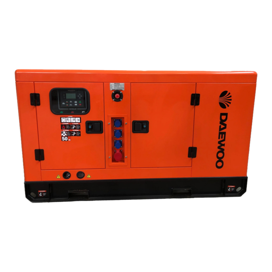
- Page 1 DAGFS-SERIES Silent diesel generator & Digital panel / Brushless synchronous A.C. Alternators USER’S MANUAL www.daewoopowerproducts.com Manufactured under license of Daewoo International Corporation, Korea...
-
Page 2: Table Of Contents
INDEX 1. SAFETY AND WARNING...........................2 2. GENERAL INTRODUCTION........................6 3. OPERATION INSTRUCTION FOR FIRST START..................8 4. MAINTENANCE............................14 5. TECHNICAL DATA...........................17 6. DIGITAL PANEL............................21 7. EXPLODED VIEW AND PARTS LIST......................28 8. EC................................48 9. WARRANTY.............................49... -
Page 3: Safety And Warning
1. SAFETY AND WARNING The operator of the machine: Is responsible for and has a duty of care in making sure that the machine is operated safely and in accordance with the instructions in this user manual. Should never leave it in a condition, which would allow an untrained or unauthorised person/s to operate this machine. - Page 4 The generator set shall be operated only by the staffs who have received training on the operation and the repair shall be made by the authorized staffs. Operator and maintenance staff shall be clear about safety and preventive actions and operation maintenance procedure. The generator sets can only be started under safety conditions.
- Page 5 shall be used to make power distribution. When the installation of generator set involves with welding, please do not connect to the ground circuit or make grounding through generator set (engine) so that to avoid the big current generated from welding operation hurt the electric appliance, bearing and bearing bush etc. inside of the generator set.
- Page 6 CHEMICAL WARNING • Ensure that the generating set room is properly ventilated. • Keep the room, the oor and the generating set clean. When spills of fuel, oil, battery electrolyte or coolant occur, they should be cleaned up immediately. • Never store ammable liquids near the engine. •...
-
Page 7: General Introduction
2. GENERAL INTRODUCTION GENERATOR SUPPLY SCOPE Silencer Engine Strong thick pipe with heat insulation Brand-new engine materials to reduce noise effectively and to avoid excessive temperature 11 in canopy inside Terminal Box Inside Alternator Regular internal wire connecting to Brand new brush convenient maintain less alternator Digital Control Panel... - Page 8 A. Product Test logo Our gensets offered are manufactured strictly accord to the ISO9001-2000 international quality management system. Our genset at least 1 hour on load testing from 25%,50%, 75%,100%,110%. 1. MORE 8 HOURS BOTTOM FUEL TANK WITH FUEL GUAGE High strength bending base, long-term durability, non-deformation, anti•...
-
Page 9: Operation Instruction For First Start
APPLICATION Continuous service Used as main power supply to generate electricity for several purposes: motion force, lighting, heating etc. The generator sets can continue running and allow 10% over load for 1 hour per 12 hours under variable load, which is used for remote area. Standby service Used as standby power supply to provide continue electric power for non invariable loads. - Page 10 2) Connect the battery, red wire for anode, black wire for cathode...
- Page 11 3) Press diesel pump, to exhaust air until feel pressure 4) Turn on the emergency stop button...
- Page 12 5) Use the key to turn on the generator, keep it running 6) Operating control panel, in order: STOP Manual Start...
- Page 13 Note: Go to next step if engine starts smoothly. If not, turn back to step 3, press the diese pump a few more times 7) Connect city power and output wire, attention: N is null line, U、 V、 W is firing line Wire socket above ATS use for city power,...
- Page 14 Final step: Finish set up the generator and then turn on breaker for auto protection...
-
Page 15: Maintenance
4. MAINTENANCE General outline For different types of generator sets, users need to refer to the matched engine’s operation and maintenance manual to implement correct maintenance operation. In order to obtain maximum operation safety and life expectancy of the generator sets, perio- dic maintenance is very important. - Page 16 remains in good status, we can filter the lubricant much better by change the oil filter. • Change fuel filter, clean or change first stage fuel filter core, oil water separator’s core (some of the generator sets have), check and organize fuel pipes arrangement. •...
- Page 17 high pressure water spray to clean the alternator. The humidity of alternator will decrease insulation resistance. The alternator shall be dried. Please refer to Alternator’s Operation and Maintenance Manual for the method of drying and detailed maintenance. Control panel Daily maintenance for the control panel shall ensure the cleanness of its surface, make the indicator more clear and easy for reading, and the operation button flexible and reliable.
-
Page 18: Technical Data
5. TECHNICAL DATA DAGFS-15 SILENT TYPE DIESEL GENERATOR SET Model DAGFS-15 Power 12 kW Engine Model ZH2105D Power 15 KVA Alternator Model Standby Power 13.2 kW VG-164D Frequency 50 Hz Standby Power 14.52 KVA Phase/Voltage 3 phase/ 380 V Net weight 650 kg Rated Current Size... - Page 19 DAGFS-25 SILENT TYPE DIESEL GENERATOR SET Model DAGFS-25 Power 20 kW Engine Model K4100D Power 25 KVA Alternator Model Standby Power 22 kW VG-184FS Frequency 50 Hz Standby Power 28 KVA Phase/Voltage 3 phase/ 380 V Net weight 710 kg Rated Current Size 38 A...
- Page 20 DAGFS-35 SILENT TYPE DIESEL GENERATOR SET Model DAGFS-35 Power 28 kW Engine Model K4102D Power 35 KVA Alternator Model Standby Power 30.8 kW VG-184G Frequency 50 Hz Standby Power 38.5 KVA Phase/Voltage 3 phase/ 380 V Net weight 710 kg Rated Current Size 53 A...
- Page 21 DAGFS-50 SILENT TYPE DIESEL GENERATOR SET Model Power 40 kW DAGFS-50 Engine Model ZH4105ZD Power 50 KVA Alternator Model VG-224D Standby Power 44 kW Frequency 50 Hz Standby Power 55 KVA Phase/Voltage Net weight 900 kg 3 phase/ 380 V Rated Current 76 A Size...
- Page 22 DAGFS-80 SILENT TYPE DIESEL GENERATOR SET Model Power 64 kW DAGFS-80 Engine Model R4108IZD Power 80 KVA Alternator Model 224GS Standby Power 70,4 kW Frequency 50 Hz Standby Power 88 KVA Phase/Voltage Net weight 1250 kg 3 phase/ 380 V Rated Current 121 A Size...
- Page 23 DAGFS-100 SILENT TYPE DIESEL GENERATOR SET Model Power 80 kW DAGFS-100 Engine Model R6105AZD Power 100 KVA Alternator Model 274C Standby Power 88 kW Frequency 50 Hz Standby Power 110 KVA Phase/Voltage Net weight 1400 kg 3 phase/ 380 V Rated Current 142 A Size...
-
Page 24: Digital Panel
6. DIGITAL PANEL KEY FUNCTION DESCRIPTION CONTROLLER DIMENSION PARAMETER EDITING After controller powered on,press to enter ito the parameters setting menu,the menu item as shown: 1) Press @ key to enter the menu interface after controller started,choose 1. (See Fig 1 ); 2) Press ID key to enter parameter configuration password confirm interface (See Fig 2);... - Page 25 parameter items; Press key to enter into current arameter setting menu; 5) If parameter within the range. the setting can be saed in internal FLASH of controller. If out of range, it can. A. Note: Pressing @ key at any time can exit the editor and return to main menu 1.
- Page 29 TYPICAL APPLICATIONS...
-
Page 31: Exploded View And Parts List
7. EXPLODING VIEW AND PARTS LIST (applies to all models) CYLINDER BLOCK ASSEMBLY... - Page 32 NUMBER PART NAME QUANTITY Bolt M8X45 Nut M8 Spring washerφ8 Washerφ8 Gasket of fuel pump Gear housing Bolt M8X25 Spring washerφ8 Washerφ8 Gasket of gear housing cover Gear housing cover Bolt M10X70 Spring washerφ10 Washerφ10 Front oil seal FB55X85X12 Bolt M8X22 Spring washerφ8 Washerφ8 Advanced device cover...
- Page 33 NUMBER PART NAME QUANTITY Cylinder head gasket Cylinder head bolt ( long) Cylinder head bolt ( short) Drain cock Rear cover sealing Rear cover Oil screw ZG3/8 Cylinder block assembly Stud M8X40 Combined seal washer Roof nut M10 Oil dipstick Bolt M8X20 Spring washerφ8 Washerφ8...
- Page 34 CYLINDER HEAD ASSEMBLY...
- Page 35 NUMBER PART NAME QUANTITY Bolt M8X45 Nut M8 Spring washerφ8 Washerφ8 Gasket of inlet manifold Inlet manifold Gasket of inlet pipe Inlet pipe Stud M8X50 Spring washerφ8 Washerφ8 Cylinder head assembly Gasket of exhaust manifold Exhaust manifold Bolt M8X25 Spring washerφ8 Washerφ8 Gasket of exhaust pipe Bolt M8X25...
- Page 36 NUMBER PART NAME QUANTITY Host ring Bolt M10X20 Spring washerφ10...
- Page 37 CRANK AND CONNECTING-ROD MECHANISM...
- Page 38 NUMBER PART NAME QUANTITY Bolt of crankshaft pulley Crankshaft pulley washer Crankshaft pulley Crankshaft pulley Key C10X50 Connecting-rod Piston Snap ring 28 Piston rings Piston pin Crankshaft Oil baf e disc Locating pin B10X25 Connecting-rod bearing Flywheel Flywheel bolt...
- Page 39 VALVE ACTUATING MECHANISM...
- Page 40 NUMBER PART NAME QUANTITY Idle gear shaft Idle gear Idle gear washer Bolt M8X22 Spring washerφ8 Bolt M8X30 Spring washerφ8 Camshaft washer Camshaft gear Thrust plate of camshaft Bolt M8X25 Spring washerφ8 Key C8X22 Camshaft Valve tappet Push rod Rock-arm assembly Rock-arm bolt Roof nut M8 Combined seal washerφ8...
- Page 41 FUEL SUPPLY SYSTEM...
- Page 42 NUMBER PART NAME QUANTITY Bolt M8X25 Spring washerφ8 Washerφ8 Bolt M8X25 Spring washerφ8 Washerφ8 Nut M8 Fuel-in joint Bracket for fuel lter Fuel lter Complex pipe for Income and return Fuel pump gear High pressure fuel pipe Injector assembly S529 Fuel pump assembly BH4Q90R9 Transport pipe out fuel pump Transport pipe to fuel lter...
- Page 43 LUBRICATING SYSTEM...
- Page 44 NUMBER PART NAME QUANTITY Bolt M8X16 Spring washerφ8 Washerφ8 Oil sump Gasket of oil sump Bolt M8X25 Spring washerφ8 Washerφ8 Oil lter assembly JX0810 Bolt M8X45 Spring washerφ8 Washerφ8 Bolt M8X25 Spring washerφ8 Washerφ8 Oil returned cover for turbo Gasket of oil returned cover for turbo Gasket of oil lter assembly Connected cover for oil lter Gasket of connected cover for oil lter...
- Page 45 NUMBER PART NAME QUANTITY Washerφ8 Oil pump driven gear Oil pump gear Bolt M8X40 Spring washerφ8 Oil pump assembly O ring 24X2.4 Oil strainer...
- Page 46 COOLING SYSTEM...
- Page 47 NUMBER PART NAME QUANTITY Radiator assembly Nut M12 Combined padding block for radiator Spring washerφ12 Washerφ12 Bracket of radiator Front foot Bolt M12X25 Spring washerφ12 Nut M14 Bolt M8X35 Spring washerφ8 Washerφ8 V Belt 1168 Padding block for fan Bolt M8X45 Spring washerφ8 Washerφ8 Water pump assembly...
- Page 48 NUMBER PART NAME QUANTITY Bolt M8X50 Spring washerφ8 Washerφ8 Thermostat housing cover Hoopφ26 Connected tube Inlet tube Outlet tube Hoopφ38...
- Page 49 ELECTRIC SYSTEM...
- Page 50 NUMBER PART NAME QUANTITY Bolt M12X30 Spring washerφ12 Starting motor assembly Generator assembly Bolt M8X30 Spring washerφ8 Washerφ8 Adjusted bracket of generator assembly Bolt M8X25 Spring washerφ8 Washerφ8...
- Page 51 CO.LTD are complying the rules of Machinery Directive EN 60204-1:2018; EN ISO 12100:2010; EN ISO 8528-13:2016EN 55012:2007/A1:2009; EN IC 61000-3-2:2019 EN 61000-3-3:2013+A1:2019; EN 55012:2007/A 1:2009 The DAEWOO Products authorized representative declares that these products described under "technical data" are in compliance with: Machinery Directive EN 60204-1:2018; EN ISO 12100:2010; EN ISO 8528-13:2016EN 55012:2007/A1:2009;...
-
Page 52: Warranty
WARRANTY CARD Product model Date of sale Company Serial number Client's signature Username The product is in good conditions and fully complete. Read and agree the terms of the warranty. GUARANTEE The warranty period starts from the date of sale of the products and covers 2 years for all power products. During the warranty period, free failures caused due to the use of poor-quality materials in the production and manufacturer workmanship admitted fault are removed. - Page 53 INDEX 1. SAFETY PRECAUTIONS.........................51 2. INTRODUCTION............................52 3. PRINCIPLE OPERATION........................53 4. APPLICATION OF THE GENERATOR....................53 5. INSTALLATION-PART 1..........................58 6. INSTALLATION-PART 2..........................65 7. ACCESORIES............................67 8. SERVICE AND MAINTENANCE......................70...
- Page 54 1. SAFETY PRECAUTIONS Before operating the generating set, read the generating set operation manual and this generator manual and become familiar with it and the equipment. The following symbols are used in the user manual or on the product: SAFE AND EFFICIENT OPERATION CAN ONLY BE ACHIEVED IF THE EQUIPMENT IS CORRECTLY OPERATED AND MAINTAINED.
- Page 55 2. INTRODUCTION 2.1 INTRODUCTION The generator is of brushless rotating eld design, available up to 660V at 50Hz or 60Hz. The design, build and text procedures meet a range of British, European and international stan- dards including, BS 5000, BS EN 60034 and ISO 60034, Where applicable. The generators are tted with the PMG Pilot exciter system and an automatic voltage regulator (AVR).
- Page 56 3. PRINCIPLE OPERATION 3.1 EXCITED-AVR CONTROLLED GENERATORS The main stator provides power for excitation of the exciter eld via the SX440 AVR which is the controlling device governing the level of excitation provided to the exciter eld. The AVR responds to a voltage sensing signal derived from the main stator winding By controlling the low power of the exciter eld, control of the high power requirement of the main eld is achie- ved through the recti ed output of the armature.
- Page 57 The generators have been designed for use in a maximum ambient temperature of 40°C, and altitude less than 1000 metres above sea level in accordance with Bs5000. Ambient in excess of 40°C, and altitudes above 1000 metres can be tolerated with reduced ratings-refer to the factory.
- Page 58 generator intake, particularly where the radiator cooling fan is required to draw air into the canopy. In addition the generator air intake to the canopy should be designed such that the ingress of moisture is prohibited. Preferably by use of a two stage lter. The air intake/outlet must be suitable for the air ow given in the following table with additional pressure drops less than or equal to those given in table 1 below: The generators may be tted with air f ilters.
- Page 59 Warning! No earth connections are made on the generator and reference to site regulations for earthing must be made. In correc tearthing or protection arrangements can result in personal injury or death. Fault current curves (decrement curves), together with generator reactance data, are available on request to assist the system designer to select circuit breakers.
- Page 60 1. Consult the genset builder. The genset builder should address the genset design to reduce the vibration levels as much as possibie. 2. Discuss, with 3. The impact of not meeting the above levels on both bearing and generator life expectancy. IMPORTANT! Important, refers to hazard or unsafe method or practice which can result in product damage or related equipment damage.
- Page 61 5. INSTALLATION-PART 1 5.1 LIFTING Warning! Incorrect lifting or inadequate lifting capacity can result In severe personal injury or equipment damage MINIMUM LIFTING CAPACITY REQUIRED IS AS INDICA TED ON THE LIFTING LABEL. Generator lifting lugs should not be used for lifting the complete Two lifting lugs are provided for use with a shackle and pin type lifting aid, A spreader with chains, to ensure that the lift is vertical, of suitable length and lifting capacity must be used.
- Page 62 Location dowel pins are tted to the engine ywheel. The coupling can then slide into nal location on the engine ywheel recess. The dowels must be removed and replaced by coupling bolts before the nal bolt tightening sequence. While tting and tightening the coupling bolts it will be necessary to rotate the engine cranks- haft - Generator rotor assembly.
- Page 63 CAUTION! Care should be taken not to allow any cleaning agent to come into prolonged contact with skin. Alignment of single bearing generators is critical. If necessary shim the generator feet to ensure alignment of the machined surfaces. The sequence of assembly to the engine should generally be as follows: 1.
- Page 64 5.4.1 INSULATION CHECK Insulation tests should be carried out before running the generator set, both after assembly and after installation on site. (see Section 7.1) IMPORTANT! The windings have been H.V. Tested during manufacture and further H.V. Testing may degrade the in sulation with consequent reduction in operating life.
- Page 65 Refer to Fig.5 a for location of selection links. 1. Frequency seclection 4 pole 50Hz operation LINK C-50 4 pole 60Hz operation LINK C-60 2. Stability selection terminals below 90kW LINKA-C below 550kW LINK B-C 3. Stability selection terminals LINK 2-3 LINK4-5 LINK 6-7 4.
- Page 66 5.5.1 TEST METERING/CABLING Connect any instrument wiring and cabling requited for initial test purposes with permanent or spring-clip type connectors Minimum instrumentation for testing should be line to line or line to neutral voltmeter, Hz meter, load current meteting and kW meter. If reactive load is used a power factor meter is desitable.
- Page 67 1. Run the generating set on no-load and check that speed is correct and stable. 2. Turn the STABILITY control potentiometer clockwise, then turn slowly anti-clockwise until the generator voltage starts to become unstable. The correct setting is slightly clockwise from this position ( i. E. Where the machine volts are stable but close to the unstable region).
- Page 68 The UFRO control potentiometer sets the "knee Point". Symptoms of incorrect setting are a) the light emitting diode (LED) indicator, just above the UFRO control potentiometer, being permanently lit when the generator is on load, and b) poor voltage regulation on load, i.e. ope- ration on the sloping part of the characteristic Clockwise adjustment lowers the frequency (speed) setting of the "knee point"...
- Page 69 The terminal box is arranged for glanding on the right hand side (or if speci cally ordered on the left-hand side) viewed from the end. Both panels are removable for drilling/punching to suit glands/or glanding boxes. If single core cables are taken through the terminal box side panel an insulated or non-magnetic gland plate should be tted.
- Page 70 CAUTION! Reference to local electricity regulations or safety rules should be made go ensure correct earthing procedures h ave been followed. 6.5 PROTECTION It is the responsibility of the end user and his contractors/subcontractors to ensure that the overall system protection meets the needs of any inspectorate, local electricity authority of safety rules, pertaining to the site and it's location.
- Page 71 When the remote voltage adjust potentiometer is used the link across terminals 1 & 2 must be removed. On SX440 the link 1&2 is on an adjacent terminal block. 7.2 PARALLEL OPERATION IMPORTANT! Failure to meet conditio ns 1, 2 and 3 when closing the circuit breaker, will generate excessive mechan ical a nd el ectrical stresses, resulting in equipment damage.
- Page 72 The diagrams below indicate the effect of droop in a simple two generator system: Generally 5% droop at full load current zero power factor is suf cient to ensure KVAr sharing. If the droop accessory has been supplied with the generator it will have been tested to ensure correct polarity and set to a nominal leve of droop.
- Page 73 generator. Adj ust 'DROOP' control potentiometer to give droop in line with above table. cloc- kwise rotation increases amount or droop. Refer to Fig. 5a of 5b for potentiometer locations. Note 1) Reverse polarity of the C. T. will raise the generator voltage with load. The polarities S1&S2 shown on the wiring diagrams are correct for clockwise rotation of the generator looking at the drive end.
- Page 74 Danger! Service and fault nding procedures present hazards that can result in severe personal injury or death. Only personnel quali ed to perform electrical and me chanical service should carry out these procedures. Ensure engine start circuits are disabled before commencing service or maintenance procedures. Isolate any anti-condensation heater supply.
- Page 75 The condition of the windings can be assessed by measurement of insulation resistance [IR] between phase to phase, and phase to earth. Measurement of winding insulation should be carried out:- 1. As part of a periodic maintenance plan. 2. After prolong periods of shutdown. 3.
- Page 76 Blown Air Drying Remove the covers from all apertures to allow the escape of the water-laden air. During drying, air must be able to ow freely through the generator in order to carry off the moisture. Direct hot air from two electrical fan heaters of around 1-3 KW into the generator air inlet aper- tures.
- Page 77 Once the insulation Resistance is raised to an acceptable level minimum value 10MΩ - the de supply may be removed and the exciter eld leads "X" and "XX" re-connected to their terminals on the AVR. Rebuild the genset, replace all covers and re-commission as appropriate. If the set is not to be run immediately ensure that the anticondensation heaters are energised, and retest the generator prior to running.
- Page 78 If the minimum value of 1.0MΩ is not obtained, drying out must be continued and the test repeated. If the minimum value of 1.0MΩ for all components cannot be achieved rewinding or refurbish- ment of the generator will be necessary. The generator must not be put into service until the minimum value, Of 1.0MΩ...
- Page 79 De nition of BSS000-3 Generators shall be capable of continuously withstanding linear vibration levels with amplitudes of 0.25 mm between 5 Hz and velocities of 9.0 mm/s. Between 8 Hz and 200 Hz when measu- red at any point directly on the carcass or main frame of the machine. These limits refer Only to the predominant frequency of v ibration of any complex waveform.
- Page 80 res. We does not quote life expectancy gures for bearings, but suggests practicable replace- ment intervals based on the L 10 life of the bearing, the grease and the recommendations of the bearing and grease manufacturers. For general-purpose applications, provid ing the vibra- tion levels do not exceed the levels stated in ISO8528-9* and BS5000-3* and the ambient temperature does not exceed 50°C the following approximations can be applied when * (See section on vibration)
- Page 81 8.3.2 RECHARGING (GHARGING) AIR FILTERS Charging is best done by totally immersing the dry element into a dip tank containing "Filterko- te Type k" or commercial lubricating oil SAE 20/50. oils of higher or lower viscosity are not recommended. Allow elements to completely drain before re tting the elements into the frames and putting into service.
- Page 82 8.5.1 GENERATOR WINDINGS, ROTATING DIODES and PERMANENT MAGNET GENERA- TOR (PMG) IMPORTANT! The resistances quoted apply to a standard winding. For generators having windings or voltages other than those speci ed refer to fac- tory for details. Ensure all disconnected leads are isolated and free from earth.
- Page 83 reading in one direction, and a high reading in the other. Replacement of Faulty Diodes The recti er assembly is split into two plates, the positive and negative, and the main rotor is connected across these plates. Each plate carries 3 diodes, the negative plate carrying negati- ve biased diodes and the positive plate carrying positive biased diodes.
- Page 84 8.5.2 AVR FUNCTION TEST All types of AVR's can be tested with this procedure: 1. Remove exciter eld leads X & XX (F1 &F2) from the AVR terminals X & XX (F1 &F2). 2. Connect a 60W 240V household lamp to AVR terminals X & xx (f1 &f2). 3.
- Page 85 Removal of the bearing may be effected either after the rotor assembly has been removed or more simply by removal of endbracket (s). Be sure to note the location of all components during removal to assist during the assembly process. BEARING REPLACEMENT Environment Every effort must be made to establish a clean area around the generator when removing and...
- Page 86 1. Remove 4 screws holding bearing cap. 2. Remove cap. 3. Non drive end remove wave washer and circlip (single bearing only). 4. Remove bearing cartridge housing complete with bearing (and grease f linger if tted). 5. Remove bearing form cartridge. 6.
- Page 87 1. Apply half the speci ed bearing grease ll quantity (see table 16) to the upper face of the bearing (opposite side to the bearing designation markings). 2. Thumb the applied grease into the bearing, ensuring good penetration into the raceways/- balls (use clean protective gloves).
- Page 88 4. Remove bearing cartridge housing complete with bearing. 5. Remove bearing from cartridge. 6. Discard the old bearing, 'O' rings and wave washer where tted. The bearing cap(s) and cartridge(s) must be thoroughly ushed out with clean solvent and checked for wear or damage, before re-assembly. Damaged components should be replaced before re tting the bearing.
- Page 89 Assemble Bearing and Cartridge onto the shaft 1. Heat the Bearing and Cartridge assembly to ao·c above ambient. (use induction heater, no other heat source is suitable) 2. Slied the Bearing and Cartridge assembly over the shaft, pushing it rmly against the bea- ring seating shoulder.
- Page 90 Warning! The rope sling may not be at the center of gravity of the rotor and guidance at the ends of the rotor is essential. THE FULL WELGHT OF THE ROTOR GIVEN IN THE TABLE BELOW MUST BE SUPPORTED BY THE CRANE AND SLING. If the rotor core is allowed to drop more than a few millimeters at this point, it will make contact with the stator windings and may damage them.
- Page 91 Manufactured under license of Daewoo International Corporation, Korea...
Need help?
Do you have a question about the DAGFS Series and is the answer not in the manual?
Questions and answers