
Related Manuals for QS Seamaster QSR Series

Summary of Contents for QS Seamaster QSR Series
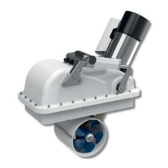
- Page 1 REV 000A series QSR 80-185 QSR 100-185 QSR 160-250 QSR 230-250 RETRACTABLE THRUSTER USER MANUAL page 3...
- Page 3 10.0 - Use of the retractable thruster Pag. 22 10.1 - Emergency closing Pag. 22 11 - Maintenance Pag. 23 12 - Disposal of the product Pag. 23 13 - Spare parts Pag. 26 OSP Spare Parts Pag. 27 Dimensions QSR SERIES USER MANUAL - REV000A...
-
Page 4: Information About The Product
QSR series 1 - Information about the product BEFORE USING THE RETRACTABLE THRUSTER, CAREFULLY READ THIS USER MANUAL. IF IN DOUBT, CONTACT YOUR NEAREST QS SEAMASTER DEALER. ® QS SEAMASTER ® RESERVES THE RIGHT TO INTRODUCE CHANGES TO THE EQUIPMENT AND THE CONTENTS OF THIS MANUAL WITHOUT PRIOR NOTICE. IN CASE OF DISCORDANCE OR ERRORS IN TRANSLATION BETWEEN THE TRANSLATED VERSION AND THE ORIGINAL TEXT IN THE ITALIAN LANGUAGE, REFERENCE WILL BE MADE TO THE ITALIAN TEXT. -
Page 5: Important Notes
THE PRODUCT MUST BE DISCONNECTED FROM THE ELECTRICAL SYSTEM BEFORE INSTALLING OR PROVIDING MAINTENANCE. QS SEAMASTER takes no responsibility regarding the inadequate connection of the users to the electrical system and to the safety of the same 3.2 - Installation requirements It is strongly recommended to entrust a professional with the preparation and positioning of the counter flange on the hull. - Page 6 • In order to prevent any damage, position the retractable thruster in such a way that the closing lid is not affected by the propulsion cone of the boat propeller (example 1 and 2), in both directions. QSR SERIES USER MANUAL - REV000A...
- Page 7 • Use a felt-tip pen to mark the counter flange at the four indicated positions on the long sides. Calculate height using this formula: Ø185 › h = 80/100mm HT (hull thickness) Ø250 › h = 130/140mm HT (hull thickness) QSR SERIES USER MANUAL - REV000A...
- Page 8 (fig. 2). • Remove the counter flange and mark the cutting area: Ø185 350x280 mm (13" 25/32 x 11" 1/32) (fig. 3A) Ø250 480x310 mm (16" 59/64 x 12" 13/64) (fig. 3B) QSR SERIES USER MANUAL - REV000A...
- Page 9 (fig. 5). Fig. 6 COUNTER FLANGE HULL • Make a solid coaming for the closing lid on the whole perimeter of the hull’s opening (fig. 6). QSR SERIES USER MANUAL - REV000A...
- Page 10 Fig. 10A Fig. 10B ANGLE BRACKET COUNTER FLANGE ANGLE BRACKET COUNTER FLANGE ANGLE BRACKET HINGE STRUCTURAL ADHESIVE HULL ANGLE BRACKET Ø185 26mm N 3 M8 SCREWS Ø250 36mm Ø185 45mm Ø250 60mm GRP LAYERS QSR SERIES USER MANUAL - REV000A...
- Page 11 Min. 90 mm HINGE Hull Max 50 mm HULL HULL 20 mm Fig. 13 • Drill the angle bracket and fasten securely also the other two M8 screws (fig. 13). N 2 SCREWS M8 QSR SERIES USER MANUAL - REV000A...
- Page 12 • Insert the motor and fix it by means of the provided screws and growers (4 units each), properly greased (fig. 15A). • Connect the faston connectors by respecting the polarity (fig. 15B). fig. 15A fig. 15B CABLE CABBLE N°6 N°5 CABLE N°7 QSR SERIES USER MANUAL - REV000A...
- Page 13 • Final installation of the cable in the lid (part. D). fig. 17 TUNNEL STEEL CABLE GUIDE STEEL LID’S BRACKET CABLE SPRINGS Ensure that the system is free to open and close without any mechanical hindrance. QSR SERIES USER MANUAL - REV000A...
- Page 14 STATUS LED becomes red: if this closing is not enough, adjust the end stroke (see sec- tion 5.8). The thruster is already adjusted at the factory, so it shouldn’t need any closing adjustment. GIUNTO OMOCINETICO QSR SERIES USER MANUAL - REV000A...
- Page 15 • Power up the thruster (fig. 22) which will automatically close. END STROKE CABLE WIRE STOPPER • In order to ensure that the thruster is properly working, open the thruster several times using the control (fig. 23). SPRING COUNTER NUT SPRING QSR SERIES USER MANUAL - REV000A...
-
Page 16: Connection Diagram
SOLENOID UNIT. QAJ1T WAIT AS LONG AS THE SYSTEM STARTS AGAIN. QAJ2T (2) THERMIC PROTECTION QAJEX EXTENSIONS (OPTIONALS) MOTOR RTC R1 ELECTRONIC BOARD BLACK SWITCH BLACK SWITCH FAST 10A FUSE BATTERY 12/24V SERVICES BATTERY QSR SERIES USER MANUAL - REV000A... - Page 17 SOLENOID UNIT. WAIT AS LONG AS THE SYSTEM STARTS AGAIN. QAJ1T QAJ2T (2) THERMIC PROTECTION QAJEX EXTENSIONS (OPTIONALS) MOTOR RTC R1 ELECTRONIC BOARD BLACK SWITCH BLACK SWITCH FAST 10A FUSE BATTERY 12/24V SERVICES BATTERY QSR SERIES USER MANUAL - REV000A...
-
Page 18: Operation
It informs the CAN control station that the thruster is in the stern (ON) Reserved (always keep off) Reserved (always keep off) 1 2 3 FACTORY SETTING: 1 = OFF , 2 = OFF , 3 = OFF , 4 = OFF 1 2 3 4 QSR SERIES USER MANUAL - REV000A... - Page 19 Check the wiring of the electric lines of QSRGTW adapter to RTC tor unit control’s output. Problem present on the The control system of the QSR propeller has detected a problem. QSR* propeller. Refer to the QSR use and maintenance manual. QSR SERIES USER MANUAL - REV000A...
- Page 20 Verify the wiring of the power lines from the board to the motor reversing contactor unit installed on the propeller. At the end of the cyclical flashing sequence, the “ERROR” LED remains off for a short period. QSR SERIES USER MANUAL - REV000A...
- Page 21 It is equipped with protections which limit its operation at a maximum time span, as reported on the controls’ man- ual. It is strongly forbidden to bypass or modify such protections in order to increase the operating time span, lest voiding the warranty and thus lifting any responsibility from QS Seamaster SPA.
-
Page 22: Maintenance
• Check that the batteries are in good conditions. • Remove the graphite residues resulting from the normal motor brushes use. WARNING: do not paint the anodes, the sealings and the gearlegs’ shafts where the propellers are lodged. QSR SERIES USER MANUAL - REV000A... -
Page 23: Disposal Of The Product
O-RING SCREW OIL SEAL SHAFT BEARING FIXATION RING EXTERNAL CIRCLIP SCREW SCREW BEARING CABLE GUIDE INTERNAL CIRCLIP EXTERNAL CIRCLIP OIL SEAL ACTUATOR’S LEVER SHAFT SUPPORT GASKET CABLE-STOPPER OIL SEAL WASHER SCREW WASHER DOUBLE JOINT QSR SERIES USER MANUAL - REV000A... - Page 24 QSR series 13 - Spare parts QSR 8018512 QSR 8018524 QSR 10018512 QSR 10018524 86 85 QSR SERIES USER MANUAL - REV000A...
- Page 25 13 - Spare parts QSR series QSR 16025024 QSR 23025024 18 17 17 28 QSR SERIES USER MANUAL - REV000A...
- Page 26 8A OSP KIT PROPELLER LH QS Ø185 8B OSP KIT PROPELLER LH QSRØ 250 OSP KIT HINGE+LID’S BRACKET QSRØ185 OSP KIT HINGE+LID’S BRACKET QSRØ250 10A OSP KIT STEEL CABLE QSRØ185 10B OSP KIT STEEL CABLE QSRØ250 QSR SERIES INSTALLATION AND USE MANUAL - REV000A...
- Page 27 B - mm (inch) 323 (12” 23/32) 384 (15” 1/8) 800 (31 MOD. QSR16025024 QSR23025024 866 (34” 3/32) 917 (36” 7/64) A - mm (inch) 443 (17” 7/16) 515 (20” 9/32) B - mm (inch) QSR SERIES INSTALLATION AND USE MANUAL - REV000A...
- Page 28 REV 000A INSTALLATION AND USE MANUAL RETRACTABLE THRUSTER Product code and serial number QS Seamaster Street Address Enrico Fermi 19, 20090 Buccinasco (MI) – Italy - Ph. +39 02488531 – Fax +39 024882545 E-mail: info@qs-seamaster.com - www.qs-seamaster.com...
Need help?
Do you have a question about the QSR Series and is the answer not in the manual?
Questions and answers