Table of Contents
Advertisement
Advertisement
Table of Contents
Troubleshooting

Related Manuals for Steris 4085


Summary of Contents for Steris 4085
- Page 1 OPERATOR MANUAL STERIS 4085 General Surgical Table (02/21/20) P150832-639...
- Page 3 Complete instructions for uncrating have been furnished. If missing, contact STERIS for a replacement copy, giving the serial, equipment and model numbers of the unit. STERIS carries a complete line of accessories for use with this table. STERIS representatives will gladly review these with you. Advisory...
- Page 4 STERIS maintains a global staff of well equipped, factory-trained technicians to provide these services, as well as expert repair services.
- Page 5 STERIS Ireland Limited IDA Business and Technology Park Tullamore County Offaly R35 X865 Ireland Manufactured by: STERIS Corporation 2720 Gunter Park East Montgomery, AL 36109 • USA TEL: 334 277 6660 FAX: 334 271 5450 www.steris.com Class 1 Equipment Type B Equipment...
- Page 6 150832-639 Operator Manual Introduction...
-
Page 7: Table Of Contents
TABLE OF CONTENTS Section Number Description Page Safety Precautions ........................1-1 Symbols on Table ..........................1-6 Symbols on Hand Control ........................1-7 Important User Information ......................2-1 Pinch Point Warnings ..........................2-1 Patient Positioning and Weight Limitation ..................... 2-3 Patient Safety Straps ..........................2-4 General Description .......................... - Page 8 TABLE OF CONTENTS (CONT’D) Section Number Description Page Routine Maintenance........................5-1 Read Before Performing Routine Maintenance ..................5-1 Cleaning Table............................5-2 5.2.1 General ............................5-2 5.2.2 After Each Usage ......................... 5-4 5.2.3 End-of-Day Cleaning Procedure ....................5-5 5.2.4 Weekly Cleaning Procedure......................5-5 Bi-Weekly Maintenance .........................
- Page 9 Connect Hand Control to STERIS 4085 General Surgical Table (Typical) ......3-4 Figure 3-4. Connect Panel........................3-5 Figure 3-5. Connect Optional Foot Control to STERIS 4085 General Surgical Table (Typical) .... 3-5 Figure 3-6. Install Head Section ......................3-6 Figure 3-7.
-
Page 10: Description Page
Description Page Figure A-4. Surgical Table Running Software Version 1.48 ..............A-4 Figure A-5. Surgical Table Running Software Version Less Than 1.47 ..........A-4 Figure A-6. Configure Universal Hand Control ..................A-5 Figure A-7. Restart Table After Selecting Compatibility Mode ............... A-6 Figure A-8. - Page 11 Equipment and Systems That Are Not Life-Supporting (per IEC 60601-2 Clause 6.8.3.201 b Table 204) ......................B-4 Table B-4 Recommended Separation Distances Between Portable and Mobile RF Communications Equipment and STERIS 4085 General Surgical Table (per IEC 60601-2 Clause 6.8.3.201 b Table 206) ............................B-5 Table of Contents Operator Manual...
- Page 12 P150832-639 Operator Manual Table of Contents...
-
Page 13: Safety Precautions
SAFETY PRECAUTIONS The following Safety Precautions must be observed when operating or servicing this STERIS 4085 General Surgical Table. WARNING indicates the potential for personal injury and CAUTION indicates the potential for damage to equipment. For emphasis, certain Safety Precautions are repeated throughout the manual. It is important to review ALL Safety Precautions before operating or servicing the unit. - Page 14 WARNING – INSTABILITY HAZARD: Possible patient or user injury, as well as table or accessory failure, may result from using STERIS table accessories for other than their stated purpose – or from using accessories manufactured and sold by other companies on STERIS surgical tables.
- Page 15 WARNING – PERSONAL INJURY AND/OR EQUIPMENT DAMAGE HAZARD: Repairs and adjustments to this equipment must be made only by STERIS or STERIS-trained service personnel. Maintenance performed by unqualified personnel or installation of unauthorized parts could cause personal injury, result in improper equipment performance, invalidate the warranty, or result in costly damage.
- Page 16 Route the hand control cord clear of any pinch points where cord could be damaged. Use of incorrect hydraulic oil may severely damage the table and/or cause malfunction. Contact STERIS for proper hydraulic oil. After performing cleaning procedures, ensure pads, tabletop and X-ray tops are completely dry before reinstalling.
- Page 17 CAUTION – POSSIBLE EQUIPMENT DAMAGE (CONT’D): Possible EMC increased EMISSIONS or decreased IMMUNITY. Do not use accessories or replacement parts not listed in the Operator or Maintenance Manuals. Surgical table operation may be affected if used adjacent to or stacked with other equipment. If adjacent or stacked use is needed, ensure table operates properly in this configuration.
-
Page 18: Symbols On Table
1.1 Symbols on Table The following is a key to symbols on the STERIS 4085 General Surgical Table. Table 1-1. Definition of Symbols on Surgical Table Symbol Definition Type B Equipment Protective Earth Ground Equipotentiality Electric Shock Hazard Control Power ON... -
Page 19: Symbols On Hand Control
Unique Device Identifier 1.2 Symbols on Hand Table 1-2 and Table 1-3 are keys to the symbols appearing on the Control STERIS 4085 General Surgical Table Hand Control and Hand Control LCD Display. Table 1-2. Definition of Symbols on Hand Control Symbol... -
Page 20: Table 1-3 Definition Of Hand Control Lcd Display Screen Icons
Table 1-2. Definition of Symbols on Hand Control (Cont’d) Symbol Definition TILT RIGHT Tilt Tabletop Right HEIGHT UP Tabletop Up (Height Up; Raise) HEIGHT DN Tabletop Down (Height Up; Lower) TREND Move Tabletop into Trendelenburg REVERSE Move Tabletop into Reverse Trendelenburg TREND FLOOR Floor Lock Function (see Table 1-3) - Page 21 Table 1-3. Definition of Hand Control LCD Display Screen Icons (Cont’d) Symbol Definition Table Powered by Battery Power. Green (Solid Icon) = Battery Fully Charged; Orange/Yellow (Half-Filled/- Solid Icon) = Battery at Half Charge; Red/Yellow (Solid Icon With Yellow !) = Battery Empty (Table Will Soon Stop Functioning).
- Page 22 1-10 150832-639 Operator Manual Safety Precautions...
-
Page 23: Important User Information
When inertia-driven or power-driven table parts close (especially Warnings during extreme tabletop articulation), pinch-point hazards exist (see Figure 2-1). All personnel involved in tabletop positioning should examine and be aware of these points before operating the STERIS WARNING – PINCHING 4085 General Surgical Table. HAZARD: Pinch points shown (circled) in Figure 2-1: •... -
Page 24: Figure 2-2. Pinch Points
FIG. 3.1 PINCH POINTS BATT -C.M Figure 2-2. Pinch Points 150832-639 Operator Manual Important User Information... -
Page 25: Patient Positioning And Weight Limitation
Do not exceed the lowest weight limit, table or accessory. WARNING – TIPPING The STERIS 4085 General Surgical Table is designed to safely HAZARD: support (with patient in normal or reverse orientation): 1100 lb (499 kg) without patient posturing or tabletop slide (except raise/ •... -
Page 26: Patient Safety Straps
2.4 General The STERIS 4085 General Surgical Table (see Figure 2-3): Description • is a mobile, electrohydraulically operated surgical table specifically designed to provide the complete patient positioning CAUTION –... -
Page 27: Technical Specifications
STERIS 4085 General Surgical Table. • The STERIS 4085 General Surgical Table should not be used adjacent to or stacked with other equipment. If so, table should be observed to verify normal operation. -
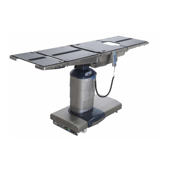
Page 28: Figure 2-3. Steris 4085 General Surgical Table Components (Typical)
7. Seat Section (Sliding) 17. Service Bar Code Label 8. Leg Section 18. Primary Fuses 9. Power Panel 19. Main Power Switch 10. Power Cord 20. AC Receptacle Figure 2-3. STERIS 4085 General Surgical Table Components (Typical) 150832-639 Operator Manual Important User Information... -
Page 29: Figure 2-4. Steris 4085 General Surgical Table Range Of Motion (Typical)
9 (227) 9 (227) (1136) (675) 80° 90° 40° 105° 90° 20° 4 (110) 30° 20° 30° 100° (51) 140° Figure 2-4. STERIS 4085 General Surgical Table Range of Motion (Typical) Important User Information Operator Manual 150832-639... -
Page 30: Weight
Line Power Input: 100-240 Vac, One-Phase, 50/60 Hz, 4.0 Amp NOTE: Each table is shipped from the factory configured to the electrical requirement specified on the factory order. If this electrical configuration needs to be changed in the field, consult STERIS for the needed procedure and required materials. -
Page 31: Image Amplification Coverage
13” 25” (330 mm) (1088 mm) (637 mm) (1088mm) (330mm) (637mm) Figure 2-6. STERIS 4085 General Surgical Table Image Amplification Coverage 2.5.7 Environmental Temperature: 63-77°F (17-25°C) Conditions Relative Humidity: 20-80% RH Atmospheric Pressure: 700-1060 hPa 2.5.8 Image Amplification 2-6. IGURE Coverage 2.5.9 Transportation/Storage... - Page 32 2-10 150832-639 Operator Manual Important User Information...
-
Page 33: Installation Instructions
INSTALLATION INSTRUCTIONS Check the overall condition of the STERIS 4085 General Surgical WARNING – PERSONAL Table and any applicable accessories upon receipt to ensure INJURY HAZARD: nothing was damaged during shipment. If damage appears to have occurred, contact the shipping company and STERIS. -
Page 34: Figure 3-1. Install/Remove Battery Fuse
Figure 3-1. Install/Remove Battery Fuse NOTE: A green Main Power Switch indicates facility power is available to the STERIS 4085 General Surgical Table. A lighted plug symbol on the LED Display indicates the batteries are charging. Refer to S ECTION 5.5, B... -
Page 35: Figure 3-2. Connect Steris 4085 General Surgical Table To Facility Power (Typical)
Ensure caps cover SERVE Foot End Head End Figure 3-2. Connect STERIS 4085 General Surgical Table to Facility Power (Typical) Install head section as follows: a. Fully loosen both locking thumbscrews located at bottom edge of back frame (see Figure 3-6). -
Page 36: Figure 3-3. Connect Hand Control To Steris 4085 General Surgical Table (Typical)
Control Panel NNECTING Click Figure 3-3. Connect Hand Control to STERIS 4085 General Surgical Table (Typical) b. Insert both leg section installation rods into seat frame until fully engaged. Listen for "click" sound to indicate correct installation (see Figure 3-8). -
Page 37: Figure 3-4. Connect Panel
Figure 3-4. Connect Panel Protective Cover Control Ensure caps cover Panel sockets when not in use. SERVE Click NNECTING Disconnect Foot Control Connect Foot Control Figure 3-5. Connect Optional Foot Control to STERIS 4085 General Surgical Table (Typical) Installation Instructions Operator Manual 150832-639... -
Page 38: Figure 3-6. Install Head Section
Figure 3-6. Install Head Section LCD Display Tabletop Positioning Primary Hand Control Symbols Figure 3-7. Hand Control LCD Display WARNING – PERSONAL «Click» INJURY HAZARD: Do not exceed 350 lb (159 kg) on the leg section. Figure 3-8. Attaching Leg Section (Typical) 150832-639 Operator Manual Installation Instructions... -
Page 39: Operating Instructions
OPERATING INSTRUCTIONS 4.1 Operating Table Operate the STERIS 4085 General Surgical Table as follows: 1. Review Pinch Point Warnings as presented in S 2.1, P ECTION INCH WARNING – PERSONAL of this manual. OINT ARNINGS INJURY HAZARD: STERIS 4085 General Surgical Table is equipped with INTELLIPOWER ®... -
Page 40: Figure 4-2. Head Section Operation (Typical)
NOTE: A patient grounding post/potential equalization terminal (male column before applying connector, DIN 42801) is provided. The mating female connector for chest compressions. patient grounding is not furnished by STERIS. WARNING – PERSONAL INJURY HAZARD: Do not exceed 350 lb (159 kg) on the leg section. -
Page 41: Hand Control
The hand control is reactivated by depressing ANY button but STOP. The STERIS 4085 General Surgical Table is equipped with a hand control (see Figure 4-3). This hand control contains easy-to-read ICONs and illuminates the key pad for easy articulation identification when room is dark. -
Page 42: Figure 4-3. Steris 4085 General Surgical Table Primary Hand Control
LCD Display Figure 4-3. STERIS 4085 General Surgical Table Primary Hand Control SLIDE FOOT: When depressed, Zip-Slide moves tabletop toward foot end. When slide returns to central ("0") position, movement stops for one second before continuing. LCD Display Slide Head ICON (refer to Table 1-3) displays. - Page 43 TILT LEFT: When depressed, the tabletop rolls to the left (patient's left or viewing the table from the head end). TILT RIGHT: When depressed, the tabletop rolls to the right (patient's right or viewing the table from the head end). BACK UP: When depressed, the tabletop back section raises.
-
Page 44: Hand Control Lcd Display Description
4.2.2 Hand Control LCD The Hand Control is equipped with a LCD (Liquid Crystal Display) Display Description Display to assist in the table operation (see Figure 4-4). The LCD Display indicator descriptions are as follows: NOTE: Numbers in ( ) refer to items shown in Figure 4-4. LCD Display (1): displays any control system messages to the user about table operation. -
Page 45: Optional Foot Control Operation
The hand control is reactivated by depressing ANY button but STOP. 4.4 Optional Foot The STERIS 4085 General Surgical Table may be operated using the Control Operation optional foot control as follows: 1. Connect foot control cord to appropriate control panel socket on table column (refer to Figure 3-5). -
Page 46: Backup (Override) Control System Operation
Figure 4-5. Backup (Override) Control System 4.5.2 Backup Hand Control The Backup Hand Control pushbutton descriptions are as follows Description (Figure 4-6): NOTE: Simply release the Backup Hand Control pushbutton when desired STERIS 4085 General Surgical Table Tabletop position has 150832-639 Operator Manual Operating Instructions... - Page 47 been reached and table automatically stops and locks in position. Refer to S 2.5.2, R , for the positioning of the ECTION ANGE OF OTION following table functions. SLIDE HEAD: When depressed, Zip-Slide moves tabletop toward head end. When slide returns to central ("0") position, movement stops for one second before continuing.
-
Page 48: Return Backup Control System
FLOOR LOCK UNLOCK Figure 4-6. Backup (Override) Hand Control 4.6 Leg Section The STERIS 4085 General Surgical Table leg section is designed to Removal be easily removed (Hi-Lock ™ locking mechanism) to enable procedures requiring optional leg supports. Remove the leg section as follows: 1. -
Page 49: Figure 4-7. Leg Section Removal
Handle Figure 4-7. Leg Section Removal 4.7 Table Pads The conductive Tabletop Pads (see Figure 4-8) are backed with fastening strips which fasten to mated strips on the tabletop. To install, proceed as follows: 1. Place pads in position and firmly press fastening strips together. 2. -
Page 50: X-Ray Top Installation
4.8 X-Ray Top The STERIS 4085 General Surgical Table is designed to enable Installation installation of an X-ray top to allow use of X-ray cassette film. Attach the four-part X-ray top as follows (see Figure 4-9): 1. Carefully remove X-ray top sections from packing container. -
Page 51: Accessories/Side Rails
4.9 Accessories/Side The standard STERIS permanently attached 3/8" wide x 1-1/8" tall Rails side rails allow for the use of many standard surgery table attachments and accessories. The rails consist of one rail mounted to each side of each tabletop main section. - Page 52 4-14 150832-639 Operator Manual Operating Instructions...
-
Page 53: Routine Maintenance
5.6 for R . Any maintenance procedures ECTION EPLACEMENT ARTS not included in this section should be performed only by STERIS- trained service personnel fully acquainted with the STERIS 4085 WARNING – PERSONAL General Surgical Table. INJURY AND/OR EQUIPMENT DAMAGE HAZARD: NOTE: Anytime table covers have been removed, the table must be •... -
Page 54: Cleaning Table
2) The use of H2O2 + PAA (Hydrogen Peroxide + Peracetic Acid) sufficient cleaning/ is strongly discouraged for use on all STERIS products. disinfection properties. 3) Always follow manufacturer instructions for concentrations and use of cleaning products. - Page 55 To ensure prolonged use of STERIS mattresses and pads, abide by following cleaning instructions: 1. Inspect mattress prior to and/or after use to check for mattress integrity. 2. Follow cleaning frequency per facility protocol; however, clean all stains promptly. 3. Use hospital-grade low-level disinfectant cleaning agent appropriate for soft materials.
-
Page 56: After Each Usage
5.2.2 After Each Usage After each use of the STERIS 4085 General Surgical Table, clean/ disinfect as follows: WARNING – INFECTION NOTE: Ensure all protective covers are installed over any open HAZARD: To protect against receptacles. aerosols being reflected from potentially contaminated 1. -
Page 57: End-Of-Day Cleaning Procedure
At the end of each day, perform the cleaning procedures as outlined Procedure 5.2.2, A ECTION FTER SAGE 5.2.4 Weekly Cleaning After each weekly use of the STERIS 4085 General Surgical Table, Procedure clean/disinfect table as follows: 1. Perform Steps 1 through 4 of 5.2.2, A ECTION FTER SAGE 2. -
Page 58: Battery Charging Procedure
Power Panel. Lead acid batteries last longer if not fully discharged. Therefore, to obtain the longest life and capacity from your STERIS 4085 General Surgical Table batteries, always connect ac power cord to table base and plug into an appropriate ac receptacle as often as possible, and as long as possible, with the Main Power Switch set to ON. -
Page 59: Replacement Parts
5.6 Replacement Parts The parts listed in this section are those necessary to do minor maintenance on the STERIS 4085 General Surgical Table. To order replacement parts, proceed as follows: 1. Include part number and description listed in Table 5-1. -
Page 60: Table 5-1 Replacement Parts
3. Send your order directly to STERIS. NOTE: For Replacement Parts, note the following: 1) Use only STERIS authorized parts on the equipment. Use of unauthorized parts voids the warranty. 2) This table uses lead-acid batteries. Lead-acid batteries normally are subject to self-discharge and battery-life deterioration in long-term storage. -
Page 61: Als Check
KIDNEY Elevator and lateral tilt. b. Trendelenburg and back. c. Leg. 4. Use a level and ensure tabletop is level. If not, call STERIS. 5.9 Auxiliary Control Check the STERIS 4085 General Surgical Table auxiliary control Check system as follows: 1. -
Page 62: Sealing Table Covers
3. Ensure tabletop raises correctly. If not, call STERIS. 5.10 Sealing Table Whenever the Table Column cover assembly and/or Table Base cover Covers are removed and then returned, the covers need sealed to prevent fluid intrusion to meet IPX4 requirements. Seal the covers as follows: NOTE: Remove all old sealant and clean all mating parts before reapplying the silicone sealant. -
Page 63: Figure 5-5. Apply Rtv To V-Shaped Cut-Outs
Figure 5-4. Seal Mating Areas Between Front and Rear Base Covers 4. Apply RTV to bottom of each V-shaped cut-out around interface with column covers (see 5-5). IGURE Figure 5-5. Apply RTV to V-Shaped Cut-Outs 5. Seal area where power supply inlet is exposed through base (see 5-6). -
Page 64: One-Part Base Cover (Plastic)
Figure 5-7. Seal Around Upper Plastic Covers and Column 7. Seal along both seams of upper plastic column covers as shown 5-8. IGURE Figure 5-8. Seal Along Both Seams of Upper Plastic Column Covers 8. Install lower (inner) column cover around column. 9. -
Page 65: Figure 5-9. Install Base Cover Insert And Attach To Base Cover
Screw Figure 5-9. Install Base Cover Insert and Attach to Base Cover 3. Apply RTV to seam between base cover insert and base cover (see 5-10). IGURE Figure 5-10. Seal Seam Between Base Cover Insert and Base Cover 4. Apply RTV around base perimeter where column shrouds attach. 5. - Page 66 5-14 150832-639 Operator Manual Routine Maintenance...
-
Page 67: Troubleshooting
ECTION OUTINE AINTENANCE • Failure to perform periodic STERIS. Service charges may be incurred, consult your warranty for inspections of the table details. A trained service technician will promptly place your STERIS could result in serious 4085 General Surgical Table in proper working order. -
Page 68: Table 6-1 Troubleshooting Chart
STOP) is pressed . Hand control not plugged in properly – correct. Faulty hand control** – replace. Call STERIS.* Table remains on battery power even when main Incorrect power cord connection – correct. power cord is plugged into facility power. -
Page 69: Table 6-2. Troubleshooting Chart, Lcd Message
Table 6-2. Troubleshooting Chart, LCD Message FAULT DISPLAYED FAULT DESCRIPTION FAULT ACTION 1 KEY ONLY Two pushbuttons are pressed at the same Press one button at a time or replace Hand time Control for defective button. DUAL COMMAND Commands are sent from the optional foot Hand control has priority. - Page 70 Table 6-2. Troubleshooting Chart, LCD Message (Cont’d) FAULT DISPLAYED FAULT DESCRIPTION FAULT ACTION VOLTAGE PEAK Battery voltage reaches 31 V (batteries are Immediately disconnect power cord; overcharging which can damage table). replace power supply Check for shorted solenoid valve (67 VALVE FAIL Valve does not shut off.
-
Page 71: Disposal Hazards
(Cu), and copper alloys (Cu/x), plastic, synthetic rubber, and/or cause malfunction. plating (Cr, Ni, Zn, Au), and adhesives not known to require special Contact STERIS for proper disposal methods at date of this manual. hydraulic oil. Hydraulic Oil: contained in hydraulic components located in the base, column, leg section, back section, and hydraulic system lines and hoses. - Page 72 150832-639 Operator Manual Disposal Hazards...
-
Page 73: A Appendix A - Universal Hand Control
General Surgical Tables unless noted otherwise. The Universal Hand WARNING – PERSONAL INJURY AND/OR EQUIPMENT Control is not to be used with the STERIS 5085 SRT Surgical Tables. Failure to comply with the safety information contained within this DAMAGE HAZARD: Read and... - Page 74 See Table A-1 for Symbol Definition Hand Control Display Normal Display Shows fully charged battery powering surgical table. Floor locks engaged and kidney bridge is up. Slide is positioned six inches toward patient’s head. Error Display Shows table is powered by low battery and a position sensor is not operating correctly.
-
Page 75: Table A-1 Symbol Definition
Table A-1. Symbol Definition Symbol Color Definition Green POWER: Table is connected to facility power Green POWER: Table is running with a fully charged battery Orange/ POWER: Table is running with a half-charged battery Yellow Red/Yellow POWER: Table is running with a discharged battery Green FLOOR LOCK STATUS: Floor locks are engaged Orange... -
Page 76: Universal Hand Control Compatibility Mode
‘TCV’ and type of Surgical Table connected. Figure A-3 shows display when Universal Hand Control is connected to Cmax/ 4085 Surgical Table equipped with version 2 table control chassis or to a 5085 Surgical Table. Figure A-3. Hand Control Software and Table Software Displayed 4. - Page 77 Control detects a table type that differs from existing compatibility mode. c. Figure A-6 shows display when a Cmax/4085 Surgical Table is detected while Universal Hand Control is configured for a 5085 Surgical Table or when a 5085 Surgical Table is detected while Universal Hand Control is configured for a Cmax/4085 Surgical Table.
-
Page 78: Universal Hand Control And Surgical Table Compatibility Modes Do Not Match
Manual symbol appears in lower right corner button. Power table Chassis of display. When table is powered on again, on by pressing any user is prompted to select 4085 Compatibility key except STOP Mode. and select 4085 Mode when prompted. -
Page 79: Table A-3 Display Screen Numeric Error Codes
ALARM - Controller button If no button found depressed, press STOP to stop any table depressed too long. movement and call STERIS. If button was pressed for more than one minute, release button and repress for less than one minute. - Page 80 Combination movements (Level, Flex and Reflex) are not recalibration. allowed. Call STERIS Service. ALARM - Battery fuse Protection fuse not installed or has failed. Call STERIS Service missing or bad connection. to ensure fuse is installed or to replace fuse. ALARM - Battery voltage Call STERIS Service.
- Page 81 30 minutes while unlocked or 10 hours when locked. ALARM - Control PC Board Call STERIS Service. Have Control PC Board lithium real time battery failure (not installed, clock battery replaced. bad or bad contact). ALARM - Communication Ensure primary hand control is plugged into table.
- Page 82 SEE OPERATOR’S MANUAL and BEACH CHAIR MODE ERROR messages on the display. Using the Universal Hand Control configured for a Cmax/4085 also causes this error. A symbol appears in the lower right corner of the display instructing the user to refer to the operator’s manual (see Figure A-10).
-
Page 83: Table A-4 Surgical Table Available Functionality
5. Using Universal Hand Control configured to a Cmax/4085 table also causes this error. If a Cmax/4085 configuration was selected for the Universal Hand Control Compatibility Mode, please select the 5085 Compatibility Mode when prompted. A.6 Feature Matrix Table A-4 shows the functionality available for each compatible Surgical Table. - Page 84 A-12 150832-639 Operator Manual Appendix A - Universal Hand Control...
- Page 85 APPENDIX B - EMC COMPLIANCE EMC COMPLIANCE The STERIS 4085 General Surgical Table is designed for most surgical TECHNICAL DATA procedures with maximum radiological access without patient reversing. The STERIS 4085 General Surgical Table and related components are intended for use in the electromagnetic environment specified in Table B-1 through Table B-4.
- Page 86 Systems (per IEC 60601-2 Clause 6.8.3.201 a – 3 Table 201) The STERIS 4085 General Surgical Table and related components are intended for use in the electromagnetic environment specified below. The Customer or the user should ensure this STERIS 4085 General Surgical Table is used in such an environment.
-
Page 87: Table B-2 Guidance And Manufacturer's Declaration - Electromagnetic Immunity For All Equipment
Systems (per IEC 60601-2 Clause 6.8.3.201 a – 6 Table 202) The STERIS 4085 General Surgical Table and related components are intended for use in the electromagnetic environment specified below. The Customer or the user should ensure this STERIS 4085 General Surgical Table is used in such an environment. -
Page 88: Clause 6.8.3.201 B Table 204
Systems That Are Not Life-Supporting (per IEC 60601-2 Clause 6.8.3.201 b Table 204) The STERIS 4085 General Surgical Table and related components are intended for use in the electromagnetic environment specified below. The Customer or the user should ensure this STERIS 4085 General Surgical Table is used in such an environment. -
Page 89: Table B-4 Recommended Separation Distances Between Portable And Mobile Rf Communications
WARNING:Portable RF communications equipment (including peripherals such as antenna cables and external antennas) should be used no closer than 30 cm (12 inches) to any part of the 4085 General Surgical Table, including cables specified by the STERIS. Otherwise, degradation of the performance of this equipment could result. - Page 90 150832-639 Operator Manual Appendix B...
Need help?
Do you have a question about the 4085 and is the answer not in the manual?
Questions and answers