Table of Contents
Advertisement
Quick Links
About this Manual
P/N: 01.54.113174 -12
Release Date: July 2011
© Copyright EDAN INSTRUMENTS, INC. 2008-2011. All rights reserved.
Statement
This manual will help you understand the operation and maintenance of the product better. It is
reminded that the product shall be used strictly complying with this manual. User's operation
failing to comply with this manual may result in malfunction or accident for which Edan
Instruments, Inc. (hereinafter called EDAN) can not be held liable.
EDAN owns the copyrights of this manual. Without prior written consent of EDAN, any
materials contained in this manual shall not be photocopied, reproduced or translated into other
languages.
Materials protected by the copyright law, including but not limited to confidential information
such as technical information and patent information are contained in this manual, the user shall
not disclose such information to any irrelevant third party.
The user shall understand that nothing in this manual grants him, expressly or implicitly, any
right or license to use any of the intellectual properties of EDAN.
EDAN holds the rights to modify, update, and ultimately explain this manual.
Responsibility of the Manufacturer
EDAN only considers itself responsible for any effects on safety, reliability and performance of
the equipment if:
Assembly operations, extensions, re-adjustments, modifications or repairs are carried out by
persons authorized by EDAN, and
The electrical installation of the relevant room complies with international standards, and
The equipment is used in accordance with the instructions for use.
Upon request, EDAN may provide, with compensation, necessary circuit diagrams, and other
information to help qualified technician to maintain and repair some parts, which EDAN may
define as user serviceable.
I
To Purchase, Visit
Avobus.com
or call
1-800-674-3655
Advertisement
Table of Contents

Related Manuals for EDAN DUS 60


Summary of Contents for EDAN DUS 60
- Page 1 This manual will help you understand the operation and maintenance of the product better. It is reminded that the product shall be used strictly complying with this manual. User’s operation failing to comply with this manual may result in malfunction or accident for which Edan Instruments, Inc. (hereinafter called EDAN) can not be held liable.
-
Page 2: Table Of Contents
Terms Used in this Manual Table of Contents This guide is designed to give key concepts on safety precautions. Chapter 1 Introduction......................... 1 WARNING 1.1. Intended Use........................1 1.2. Features ..........................1 A WARNING label advises against certain actions or situations that could result in personal 1.3. - Page 3 5.4.4. Function Controls....................27 7.1.6. FL .......................... 88 5.4.5. Comment Function....................32 7.1.7. AFI ........................88 5.4.6. Body Mark Function ..................... 34 7.1.8. TAD........................88 5.4.7. Imaging Functions....................37 7.1.9. APAD ........................89 5.4.8. Additional Control Functions................40 7.1.10. CER ........................89 5.5.
- Page 4 9.2.1. L UT A: ....................... 121 16.1. Warranty........................144 9.2.2. R UT A: ....................... 121 16.2. Service Policy......................144 9.2.1. L OV A: ....................... 122 Appendix I: Specifications......................146 9.2.2. R OV A:....................... 122 A1.1: Electrical Safety Classifications................. 146 9.3. Gynecologic Report ..................... 122 A1.2: Standards Compliance....................
-
Page 5: Chapter 1 Introduction
The DUS 60 is intended for use by or on the order of a physician or similarly qualified health care professional for ultrasound evaluation of Fetus; Abdomen;... -
Page 6: Caution
Achievable) principles, acoustic output should be set to the lowest level required to satisfactorily Do not alter parameters of the device at will. If it is necessary, please consult EDAN perform the examination. Long time exposure should be avoided. For the parameters of sound or authorized representatives for service. - Page 7 Ultrasound machines also generate EMI. The DUS 60 complies with limits as stated on the EMC label. However, there is no 13. Periodically have the integrity of the system ground checked by a qualified service guarantee that interference will not occur in a particular installation.
-
Page 8: Battery Safety
If you find strong interference shows on the screen, please check the sources. which affects battery life. 1.5.4. Battery Safety Only use the battery and charge the battery with EDAN equipment, and charge the battery with the system. To prevent the battery from igniting, emitting fumes, bursting, injuring personal, damaging To avoid the possibility of electrostatic shock and damage to the battery, avoid using equipment, pay attention to the following precautions. - Page 9 DUS 60 Digital Ultrasonic Diagnostic Imaging System User Manual Introduction DUS 60 Digital Ultrasonic Diagnostic Imaging System User Manual Introduction 1.6. Labeling Symbols Net work port Foots witch Descriptions of symbols of the device are shown in table 1-1. To identify a footswitch or the connection for a footswitch.
-
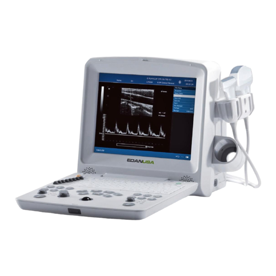
Page 10: Chapter 2 System Overview
DUS 60 Digital Ultrasonic Diagnostic Imaging System User Manual System Overview DUS 60 Digital Ultrasonic Diagnostic Imaging System User Manual System Overview Chapter 2 System Overview 2.1.2. Rear View 2.1. Appearance 2.1.1. Front View Figure 2-2 Rear View Probe sockets... -
Page 11: Configuration
DUS 60 Digital Ultrasonic Diagnostic Imaging System User Manual System Overview DUS 60 Digital Ultrasonic Diagnostic Imaging System User Manual System Overview NOTE:Calibration should be performed because HP2418 and HP2488 printers will print 2.2. Configuration out calibration paper every time after replacing jet box, Please perform the calibration according to the operation method on the calibration paper. -
Page 12: Chapter 3 Transportation And Storage
DUS 60 Digital Ultrasonic Diagnostic Imaging System User Manual Transportation and Storage DUS 60 Digital Ultrasonic Diagnostic Imaging System User Manual Installation Instructions Chapter 3 Transportation and Storage Chapter 4 Installation Instructions 3.1. Moving the System 4.1. Environmental Requirements The system is designed to be portable and easily transported. Power off the system and secure all Keep the device away from equipment with strong electric field, strong magnetic and high accessories before moving it to another location. -
Page 13: Installing And Uninstalling A Cable Holder
DUS 60 Digital Ultrasonic Diagnostic Imaging System User Manual Installation Instructions DUS 60 Digital Ultrasonic Diagnostic Imaging System User Manual Installation Instructions 4.3.1. Installing and Uninstalling a Cable Holder 4.3.2. Installing and Uninstalling a Battery To install the cable holder: To install a battery (if necessary): 1. -
Page 14: Connecting And Disconnecting Probes
The scan direction mark is shown below. Scan Direction Mark 4.3.4. Peripheral Connections Video connections are located on the left panel of the DUS 60. WARNING Accessory equipment connected to the analog and digital interfaces must be certified Figure 4-5 Probe Scan Direction Mark Schematic Diagram according to the respective IEC/EN standards (e.g. -
Page 15: Equipotential Bonding
DUS 60 Digital Ultrasonic Diagnostic Imaging System User Manual Installation Instructions CAUTION 4.3.5. Equipotential Bonding To ensure proper grounding and leakage current levels, it is the policy of EDAN to have Equipotential terminal Rear panel Potential equalization conductor an authorized EDAN representative or EDAN approved third party perform all on-board connections of documentation and storage devices to the DUS 60. -
Page 16: Printer Installation
60 system, you are suggested to calculate the system power consumption when CAUTION building a DUS 60 system so as to match the system power consumption with the 1. You are forbidden to unplug or plug the power cord before switching off the system. -
Page 17: Examining
DUS 60 Digital Ultrasonic Diagnostic Imaging System User Manual System Control DUS 60 Digital Ultrasonic Diagnostic Imaging System User Manual System Control To restart the device 5.3. Screen Layout If there is any trouble described as below, please press the power on/off key to switch off the device and then press it again to restart the device. -
Page 18: Control Panel
DUS 60 Digital Ultrasonic Diagnostic Imaging System User Manual System Control DUS 60 Digital Ultrasonic Diagnostic Imaging System User Manual System Control Move the sample line in the PW mode. 5.4. Control Panel Realize single frame playback in the frame-by-frame playback status. - Page 19 DUS 60 Digital Ultrasonic Diagnostic Imaging System User Manual System Control DUS 60 Digital Ultrasonic Diagnostic Imaging System User Manual System Control File management key Frequency Shift Key Press this key to enter or to exit the file management system.
- Page 20 DUS 60 Digital Ultrasonic Diagnostic Imaging System User Manual System Control DUS 60 Digital Ultrasonic Diagnostic Imaging System User Manual System Control Image up/down Flip key Rotate it to adjust total gain in the B mode, 0 ~ 130, in increments of Press this key to flip the image vertically.
-
Page 21: Comment Function
DUS 60 Digital Ultrasonic Diagnostic Imaging System User Manual System Control DUS 60 Digital Ultrasonic Diagnostic Imaging System User Manual System Control To add an arrow: levels are available: ×1.0, ×1.44, ×1.96, ×2.56, ×4.0, ×5.76, ×9.0 and 16.0. Press Set display the zoomed image, and then roll the 1. -
Page 22: Body Mark Function
DUS 60 Digital Ultrasonic Diagnostic Imaging System User Manual System Control DUS 60 Digital Ultrasonic Diagnostic Imaging System User Manual System Control button to adjust the probe scanning direction. 4. Press Set to complete adding the body mark. To move a body mark: 1. -
Page 23: Imaging Functions
DUS 60 Digital Ultrasonic Diagnostic Imaging System User Manual System Control DUS 60 Digital Ultrasonic Diagnostic Imaging System User Manual System Control Twins Cardiology Small parts 1 Urology Figure 5-4 Body Marks 5.4.7. Imaging Functions B mode Imaging Control Small parts 2 Press this key to enter the B mode. - Page 24 DUS 60 Digital Ultrasonic Diagnostic Imaging System User Manual System Control DUS 60 Digital Ultrasonic Diagnostic Imaging System User Manual System Control Image Display window, while acquiring Pulsed-Wave Doppler data in the Time Series window. Operation: 4B mode Imaging Control In the B scan, the long line lets you adjust the sample line position, the two parallel lines (that Press this key to enter the 4B mode.
-
Page 25: Additional Control Functions
5.4.8. Additional Control Functions 5.5. Menu The DUS 60 also provides the following additional control functions, which are available through status menus. Menus are displayed on the right of the screen. Only one menu can be activated at a time. The... -
Page 26: Dialog Box Operation
DUS 60 Digital Ultrasonic Diagnostic Imaging System User Manual System Control DUS 60 Digital Ultrasonic Diagnostic Imaging System User Manual System Control Measurement and calculation menu Perform an operation. For instance, begin a distance measurement, and then the corresponding measurement cursor is displayed. -
Page 27: Displaying / Modifying Presetting Parameters
DUS 60 Digital Ultrasonic Diagnostic Imaging System User Manual System Control DUS 60 Digital Ultrasonic Diagnostic Imaging System User Manual System Control Figure 5-11 Preset Menu (the left—with no DICOM installed, and the right—with DICOM installed) Figure 5-12 General Presetting Dialog Box 2. -
Page 28: Presetting Examination
DUS 60 Digital Ultrasonic Diagnostic Imaging System User Manual System Control DUS 60 Digital Ultrasonic Diagnostic Imaging System User Manual System Control highlight Obstetric and press Set to display obstetric examination presetting dialog box. Date Set freely Set the system date. -
Page 29: Presetting Formula
DUS 60 Digital Ultrasonic Diagnostic Imaging System User Manual System Control DUS 60 Digital Ultrasonic Diagnostic Imaging System User Manual System Control Parameter 2 Tab IP Tab NOTE: IP----Image Parameter Figure 5-14 Obstetric Presetting – Parameter 2 Tab Item Setting Allows you to Figure 5-15 Obstetric Presetting –... -
Page 30: Presetting Post Processing
DUS 60 Digital Ultrasonic Diagnostic Imaging System User Manual System Control DUS 60 Digital Ultrasonic Diagnostic Imaging System User Manual System Control 5.7.6. Presetting Post Processing The preset items include gray map, rejection and gamma correction. In the preset menu, roll the trackball to highlight Post-Proc and press Set, and then display post... -
Page 31: Editing Comment Library
DUS 60 Digital Ultrasonic Diagnostic Imaging System User Manual System Control DUS 60 Digital Ultrasonic Diagnostic Imaging System User Manual System Control closed. Gamma correction presetting (γ correction): γ correction has four levels: 0, 1, 2 and 3. You can select any one of the four levels. -
Page 32: Presetting Data
DUS 60 Digital Ultrasonic Diagnostic Imaging System User Manual System Control DUS 60 Digital Ultrasonic Diagnostic Imaging System User Manual System Control 4. Roll the trackball to highlight the right side frame of User-defined, and press Set. Then the Item Description cursor turns to “... -
Page 33: Chapter 6 Operation
4. Do not cut off the printer power supply or the USB cable during printing. To switch the input text box: press Enter; 5. If the printer can not work normally, please restart the printer and the DUS 60. To enter the patient information, use the keyboard;... - Page 34 DUS 60 Digital Ultrasonic Diagnostic Imaging System User Manual Operation DUS 60 Digital Ultrasonic Diagnostic Imaging System User Manual Operation mode. Distance and circumference will be presented in mm; area, in mm or dm ; volume, in mm mL or L; time in ms or s, and heart rate in bpm, etc.
- Page 35 DUS 60 Digital Ultrasonic Diagnostic Imaging System User Manual Operation DUS 60 Digital Ultrasonic Diagnostic Imaging System User Manual Operation The system-defined examinations are abbreviated as follows: Circumference/Area Ellipse Method Abd: Abdominal; OB: Obstetric; Sml: Small Parts; Gyn: Gynecology; Ortho: Orthopedics To measure Circumference / Area: Urol: Urology;...
- Page 36 DUS 60 Digital Ultrasonic Diagnostic Imaging System User Manual Operation DUS 60 Digital Ultrasonic Diagnostic Imaging System User Manual Operation trackball, the system displays dots to outline the structure. To correct To measure volume: an error in the trace, press Back to move in reverse along the traced In the B mode outline.
- Page 37 DUS 60 Digital Ultrasonic Diagnostic Imaging System User Manual Operation DUS 60 Digital Ultrasonic Diagnostic Imaging System User Manual Operation by calculating 3 sets of distance data, L, W, and H. Measure the three 4. Measure the second distance B, move the cursor and press Set to pieces of data in the method of B mode generic distance measurement, anchor the start point, and the mark “+”...
- Page 38 DUS 60 Digital Ultrasonic Diagnostic Imaging System User Manual Operation DUS 60 Digital Ultrasonic Diagnostic Imaging System User Manual Operation value and calculation result. and the end point. 5. During measurement, you can press Change to change the start point 6.
-
Page 39: Others
DUS 60 Digital Ultrasonic Diagnostic Imaging System User Manual Operation DUS 60 Digital Ultrasonic Diagnostic Imaging System User Manual Operation the measurement result window. These are for B/M and M display modes only. The default measurement of B/M and M mode is heart rate measurement. - Page 40 DUS 60 Digital Ultrasonic Diagnostic Imaging System User Manual Operation DUS 60 Digital Ultrasonic Diagnostic Imaging System User Manual Operation the measurement result window, as shown below. following two complete cycles and then press Set to anchor end position. 6. Press Measure to finish and exit.
- Page 41 DUS 60 Digital Ultrasonic Diagnostic Imaging System User Manual Operation DUS 60 Digital Ultrasonic Diagnostic Imaging System User Manual Operation 4. Roll the trackball and press Set to begin a new velocity measurement. You can measure a maximum of four groups of data. The outcome will be displayed in the measurement result window, as shown below.
- Page 42 DUS 60 Digital Ultrasonic Diagnostic Imaging System User Manual Operation DUS 60 Digital Ultrasonic Diagnostic Imaging System User Manual Operation 6. Roll the trackball and press Set to begin a new tracing measurement. You can 6.7. CINE Review measure a maximum of four groups of data. The outcome will be displayed in the measurement result window.
- Page 43 DUS 60 Digital Ultrasonic Diagnostic Imaging System User Manual Operation DUS 60 Digital Ultrasonic Diagnostic Imaging System User Manual Operation 2. Cine review can’t be performed at the beginning of scanning or probe switching. You Set repeatedly to cycle between JPG, BMP, FRM and DCM (if DICOM is installed).
- Page 44 DUS 60 Digital Ultrasonic Diagnostic Imaging System User Manual Operation DUS 60 Digital Ultrasonic Diagnostic Imaging System User Manual Operation Save As When obtaining a satisfying image: 1. Press File and select Save As…in the file menu to display the File Save As dialog box.
- Page 45 DUS 60 Digital Ultrasonic Diagnostic Imaging System User Manual Operation DUS 60 Digital Ultrasonic Diagnostic Imaging System User Manual Operation You can use the file manager to perform the file management. After you open an image, you can perform the image viewing as shown in section 6.8.3.
- Page 46 DUS 60 Digital Ultrasonic Diagnostic Imaging System User Manual Operation DUS 60 Digital Ultrasonic Diagnostic Imaging System User Manual Operation To delete all: To send a DCM file 1. Roll the trackball to select the driver and the type of file, and then press Set.
- Page 47 DUS 60 Digital Ultrasonic Diagnostic Imaging System User Manual Obstetric Measurements and Calculations DUS 60 Digital Ultrasonic Diagnostic Imaging System User Manual Obstetric Measurements and Calculations EFW: Estimated Fetal Weight Chapter 7 Obstetric Measurements and Calculations B-OB MEAS: the default measurement is distance measurement.
- Page 48 DUS 60 Digital Ultrasonic Diagnostic Imaging System User Manual Obstetric Measurements and Calculations DUS 60 Digital Ultrasonic Diagnostic Imaging System User Manual Obstetric Measurements and Calculations The system will calculate MA and AVE EDC automatically after measuring each parameter. 3. Measure BPD, in the method of distance measurement.
- Page 49 DUS 60 Digital Ultrasonic Diagnostic Imaging System User Manual Obstetric Measurements and Calculations DUS 60 Digital Ultrasonic Diagnostic Imaging System User Manual Obstetric Measurements and Calculations 7.1.6. FL Reference Section 6.6.1, Generic Measurements in B Mode To measure FL: 4. The results are displayed in measurement result window.
- Page 50 DUS 60 Digital Ultrasonic Diagnostic Imaging System User Manual Obstetric Measurements and Calculations DUS 60 Digital Ultrasonic Diagnostic Imaging System User Manual Obstetric Measurements and Calculations 7.1.11. Reference Section 6.6.1, Generic Measurements in B Mode To measure FTA: 4. The results are displayed in measurement result window.
- Page 51 DUS 60 Digital Ultrasonic Diagnostic Imaging System User Manual Obstetric Measurements and Calculations DUS 60 Digital Ultrasonic Diagnostic Imaging System User Manual Obstetric Measurements and Calculations 3. The Fetal Biophysical Profile window displays as the following figure shows. Select the parameters from the pull-down menu of FHR, FM, FBM, FT and PL, and then press OK to confirm, the biophysical evaluation result will be displayed in the FBP Report.
- Page 52 DUS 60 Digital Ultrasonic Diagnostic Imaging System User Manual Obstetric Measurements and Calculations DUS 60 Digital Ultrasonic Diagnostic Imaging System User Manual Obstetric Measurements and Calculations NOTE: 1. In the obstetric menu, roll the trackball to highlight EFW, and then press Set.
- Page 53 DUS 60 Digital Ultrasonic Diagnostic Imaging System User Manual Obstetric Measurements and Calculations DUS 60 Digital Ultrasonic Diagnostic Imaging System User Manual Obstetric Measurements and Calculations 3. Measure Umb A, in the method of D trace measurement. 7.2.4. Desc.AO To measure Desc. AO: Reference Section 6.6.3, Generic Measurements in PW Mode...
-
Page 54: Growth Curve
DUS 60 Digital Ultrasonic Diagnostic Imaging System User Manual Obstetric Measurements and Calculations DUS 60 Digital Ultrasonic Diagnostic Imaging System User Manual Obstetric Measurements and Calculations 5. To begin a new Desc. AO measurement, repeat steps 1 through 3. You can measure a maximum of one group of data. -
Page 55: Obstetric Report
DUS 60 Digital Ultrasonic Diagnostic Imaging System User Manual Obstetric Measurements and Calculations DUS 60 Digital Ultrasonic Diagnostic Imaging System User Manual Cardiology Measurements and Calculations 7.3.2. Obstetric Report Chapter 8 Cardiology Measurements and Calculations After obstetric examination, the system will generate an obstetrical diagnosis worksheet The cardiology examination is usually in the B mode, the B/M mode or the M mode. - Page 56 DUS 60 Digital Ultrasonic Diagnostic Imaging System User Manual Cardiology Measurements and Calculations DUS 60 Digital Ultrasonic Diagnostic Imaging System User Manual Cardiology Measurements and Calculations 1. CUBE formula: 2. TEICHHOLZ formula: NOTE: d: end diastolic; s: end systolic NOTE: d: end diastolic; s: end systolic...
- Page 57 DUS 60 Digital Ultrasonic Diagnostic Imaging System User Manual Cardiology Measurements and Calculations DUS 60 Digital Ultrasonic Diagnostic Imaging System User Manual Cardiology Measurements and Calculations Aortic Valve Volume Opened, Body Surface Area (m Calculate by to the selected formula...
- Page 58 DUS 60 Digital Ultrasonic Diagnostic Imaging System User Manual Cardiology Measurements and Calculations DUS 60 Digital Ultrasonic Diagnostic Imaging System User Manual Cardiology Measurements and Calculations menu will be displayed. Select TEICHHOLZ or CUBE and press Set. Then move the cursor Roll the trackball to highlight OK and press Set.
-
Page 59: Lvmw, Lvmwi
DUS 60 Digital Ultrasonic Diagnostic Imaging System User Manual Cardiology Measurements and Calculations DUS 60 Digital Ultrasonic Diagnostic Imaging System User Manual Cardiology Measurements and Calculations E to point C respectively, in the method of generic M mode distance measurement. - Page 60 DUS 60 Digital Ultrasonic Diagnostic Imaging System User Manual Cardiology Measurements and Calculations DUS 60 Digital Ultrasonic Diagnostic Imaging System User Manual Cardiology Measurements and Calculations 2. Dual plane ellipse formula: 1. Items of Measurement and Calculation NOTE: d: end diastolic; s: end systolic B-CARDIAC MEAS: RV, LV, and PA.
- Page 61 DUS 60 Digital Ultrasonic Diagnostic Imaging System User Manual Cardiology Measurements and Calculations DUS 60 Digital Ultrasonic Diagnostic Imaging System User Manual Cardiology Measurements and Calculations LVLs Left Ventricular Length Distance (mm) Stroke Index SI (No unit)= SV (mL)/ BSA (m...
- Page 62 DUS 60 Digital Ultrasonic Diagnostic Imaging System User Manual Cardiology Measurements and Calculations DUS 60 Digital Ultrasonic Diagnostic Imaging System User Manual Cardiology Measurements and Calculations CO calculation is as below. 2. Input a suitable value in the LVET (ms) box.
-
Page 63: Others
DUS 60 Digital Ultrasonic Diagnostic Imaging System User Manual Cardiology Measurements and Calculations DUS 60 Digital Ultrasonic Diagnostic Imaging System User Manual Gynecology Measurements and Calculations 2. Measure PA in the method of distance measurement. Chapter 9 Gynecology Measurements and Calculations 3. -
Page 64: Endo
DUS 60 Digital Ultrasonic Diagnostic Imaging System User Manual Gynecology Measurements and Calculations DUS 60 Digital Ultrasonic Diagnostic Imaging System User Manual Gynecology Measurements and Calculations 2. Take three measurements, L.OV-L, L.OV-W and L.OV-H, in the method of distance R. OV-L Right Ovary Length measurement. -
Page 65: Cx-L
DUS 60 Digital Ultrasonic Diagnostic Imaging System User Manual Gynecology Measurements and Calculations DUS 60 Digital Ultrasonic Diagnostic Imaging System User Manual Gynecology Measurements and Calculations Secondary menu of the gynecology 9.1.5. CX-L measurement items in the PW mode: To measure CX-L: 1. -
Page 66: L Ov A
DUS 60 Digital Ultrasonic Diagnostic Imaging System User Manual Gynecology Measurements and Calculations DUS 60 Digital Ultrasonic Diagnostic Imaging System User Manual Gynecology Measurements and Calculations 9.2.1. L OV A: 1. Press Measure to activate the measurement. 2. In the gynecology measurement menu, select L OV A. - Page 67 DUS 60 Digital Ultrasonic Diagnostic Imaging System User Manual Small Parts Measurements and Calculations DUS 60 Digital Ultrasonic Diagnostic Imaging System User Manual Small Parts Measurements and Calculations Chapter 10 Small Parts Measurements and Calculations The measurements of THY include L.THY-V and R.THY-V.
- Page 68 DUS 60 Digital Ultrasonic Diagnostic Imaging System User Manual Small Parts Measurements and Calculations DUS 60 Digital Ultrasonic Diagnostic Imaging System User Manual Urology Measurements and Calculations Chapter 11 Urology Measurements and Calculations 11.1. Measurement and Calculation The urology examination is usually in the B mode.
- Page 69 DUS 60 Digital Ultrasonic Diagnostic Imaging System User Manual Urology Measurements and Calculations DUS 60 Digital Ultrasonic Diagnostic Imaging System User Manual Urology Measurements and Calculations To measure RUV: 1. In the urology menu, roll the trackball to highlight RUV, and then press Set.
- Page 70 DUS 60 Digital Ultrasonic Diagnostic Imaging System User Manual Orthopedics Measurements and Calculations DUS 60 Digital Ultrasonic Diagnostic Imaging System User Manual Orthopedics Measurements and Calculations The diagnosis editing column displays the cursor “І”, and you can enter diagnosis information.
- Page 71 DUS 60 Digital Ultrasonic Diagnostic Imaging System User Manual Vascular Measurements and Calculations DUS 60 Digital Ultrasonic Diagnostic Imaging System User Manual Vascular Measurements and Calculations Chapter 13 Vascular Measurements & Calculations Reference Section 6.6.3, Generic Measurements in PW Mode Usually the vascular examination is in the PW mode.
- Page 72 DUS 60 Digital Ultrasonic Diagnostic Imaging System User Manual Vascular Measurements and Calculations DUS 60 Digital Ultrasonic Diagnostic Imaging System User Manual Vascular Measurements and Calculations 2. In the vascular menu, select Vert A. 13.2. Vascular Report 3. Measure Vert A, in the method of D trace measurement.
- Page 73 DUS 60 Digital Ultrasonic Diagnostic Imaging System User Manual Inspection and Maintenance DUS 60 Digital Ultrasonic Diagnostic Imaging System User Manual Inspection and Maintenance each part to remove any surface particles. Disinfect the parts to kill vegetative organisms and Chapter 14 Inspection and Maintenance viruses.
- Page 74 DUS 60 Digital Ultrasonic Diagnostic Imaging System User Manual Inspection and Maintenance DUS 60 Digital Ultrasonic Diagnostic Imaging System User Manual Inspection and Maintenance NOTE:The single-use sheath should be used on E743UA probe and E613UA probe. 14.2.1. System Surface Cleaning Before cleaning the probe, remove the sheath gently and discard it.
- Page 75 Step 2. Use the tweezers to pull the fuses out through the small hole on the bottom of the box; WARNING Step 3. Put new fuses (φ5×20, T3.15AH250V) provided by EDAN in position, and reposition The DUS 60 cannot be used together with high-frequency surgical equipment.
- Page 76 The leakage current should never exceed the limit. The data should be recorded in an equipment log. If the device is not functioning properly or any of the above tests fail, please contact the maintenance personnel of EDAN. - 142...
- Page 77 EDAN will, at its discretion, repair or replace the defective part(s) free of charge. EDAN will not provide a substitute product for use when the defective product is being repaired.
-
Page 78: A1.1: Electrical Safety Classifications
DUS 60 Digital Ultrasonic Diagnostic Imaging System User Manual Specifications DUS 60 Digital Ultrasonic Diagnostic Imaging System User Manual Specifications A1.3: Power Supply Appendix I: Specifications Operating Voltage 100 V-240 V~ A1.1: Electrical Safety Classifications Operating Frequency 50 Hz/60 Hz... -
Page 79: A1.6: General Technical Specifications
DUS 60 Digital Ultrasonic Diagnostic Imaging System User Manual Specifications DUS 60 Digital Ultrasonic Diagnostic Imaging System User Manual Specifications A1.6: General Technical Specifications A1.7: Probe Specifications This device can detect the probe automatically. Display Modes B, B+B, 4B, B+M, M, and PW... -
Page 80: A1.8: Operating, Storage And Transportation Environment
DUS 60 Digital Ultrasonic Diagnostic Imaging System User Manual Specifications DUS 60 Digital Ultrasonic Diagnostic Imaging System User Manual Ultrasound Intensity and Safety Length of Appendix II: Ultrasound Intensity and Safety probe 2200±50 mm cable A2.1: Ultrasound in Medicine Mode Transducer Models Parameter(mm)... -
Page 81: A2.3: Probe Acoustic Output Parameters List
DUS 60 Digital Ultrasonic Diagnostic Imaging System User Manual Ultrasound Intensity and Safety DUS 60 Digital Ultrasonic Diagnostic Imaging System User Manual Ultrasound Intensity and Safety equivalent to a higher power output. Operator Control Features: The user should be aware that certain operator controls may affect the acoustic output. It is Proper use of these instrument settings can minimize patient exposure, and optimize the results and efficiency of the equipment. - Page 82 DUS 60 Digital Ultrasonic Diagnostic Imaging System User Manual Ultrasound Intensity and Safety DUS 60 Digital Ultrasonic Diagnostic Imaging System User Manual Ultrasound Intensity and Safety Control1: AP=15; Frequency=3.0MHz; Depth=98mm; Focus=60mm; Acoustic Output Reporting Table Acoustic Output Reporting Table Transducer Model: C321UA...
-
Page 83: A2.3.2 : Test Of Probe C613Ua
DUS 60 Digital Ultrasonic Diagnostic Imaging System User Manual Ultrasound Intensity and Safety DUS 60 Digital Ultrasonic Diagnostic Imaging System User Manual Ultrasound Intensity and Safety Acoustic Output Reporting Table A2.3.2 : Test of Probe C613UA: Transducer Model: C321UA Operating Model: PW Mode... - Page 84 DUS 60 Digital Ultrasonic Diagnostic Imaging System User Manual Ultrasound Intensity and Safety DUS 60 Digital Ultrasonic Diagnostic Imaging System User Manual Ultrasound Intensity and Safety Acoustic Output Reporting Table Acoustic Output Reporting Table Transducer Model: C613UA Operating Model: B Mode...
-
Page 85: A2.3.3 : Test Of Probe C343Ua
DUS 60 Digital Ultrasonic Diagnostic Imaging System User Manual Ultrasound Intensity and Safety DUS 60 Digital Ultrasonic Diagnostic Imaging System User Manual Ultrasound Intensity and Safety Acoustic Output Reporting Table A2.3.3 : Test of Probe C343UA: Transducer Model: C613UA Operating Model: PW Mode... - Page 86 DUS 60 Digital Ultrasonic Diagnostic Imaging System User Manual Ultrasound Intensity and Safety DUS 60 Digital Ultrasonic Diagnostic Imaging System User Manual Ultrasound Intensity and Safety Acoustic Output Reporting Table Acoustic Output Reporting Table Transducer Model: C343UA Operating Model: B Mode...
-
Page 87: A2.3.4 : Test Of Probe L763Ua
DUS 60 Digital Ultrasonic Diagnostic Imaging System User Manual Ultrasound Intensity and Safety DUS 60 Digital Ultrasonic Diagnostic Imaging System User Manual Ultrasound Intensity and Safety Acoustic Output Reporting Table A2.3.4 : Test of Probe L763UA: Transducer Model: C343UA Operating Model: PW Mode... - Page 88 DUS 60 Digital Ultrasonic Diagnostic Imaging System User Manual Ultrasound Intensity and Safety DUS 60 Digital Ultrasonic Diagnostic Imaging System User Manual Ultrasound Intensity and Safety Acoustic Output Reporting Table Acoustic Output Reporting Table Transducer Model: L763UA Operating Model: B Mode...
- Page 89 DUS 60 Digital Ultrasonic Diagnostic Imaging System User Manual Ultrasound Intensity and Safety DUS 60 Digital Ultrasonic Diagnostic Imaging System User Manual Ultrasound Intensity and Safety Acoustic Output Reporting Table A2.3.5 : Test of Probe C362UA: Transducer Model: L763UA Operating Model: PW Mode...
- Page 90 DUS 60 Digital Ultrasonic Diagnostic Imaging System User Manual Ultrasound Intensity and Safety DUS 60 Digital Ultrasonic Diagnostic Imaging System User Manual Ultrasound Intensity and Safety Acoustic Output Reporting Table Acoustic Output Reporting Table Transducer Model: C362UA Operating Model: B Mode...
- Page 91 DUS 60 Digital Ultrasonic Diagnostic Imaging System User Manual Ultrasound Intensity and Safety DUS 60 Digital Ultrasonic Diagnostic Imaging System User Manual Ultrasound Intensity and Safety Acoustic Output Reporting Table A2.3.6 : Test of Probe L742UA: Transducer Model: C362UA Operating Model: PW Mode...
- Page 92 DUS 60 Digital Ultrasonic Diagnostic Imaging System User Manual Ultrasound Intensity and Safety DUS 60 Digital Ultrasonic Diagnostic Imaging System User Manual Ultrasound Intensity and Safety Acoustic Output Reporting Table Acoustic Output Reporting Table Transducer Model: L742UA Operating Model: B Mode...
- Page 93 DUS 60 Digital Ultrasonic Diagnostic Imaging System User Manual Ultrasound Intensity and Safety DUS 60 Digital Ultrasonic Diagnostic Imaging System User Manual Ultrasound Intensity and Safety Acoustic Output Reporting Table A2.3.7 : Test of Probe E613UA: Transducer Model: L742UA Operating Model: PW Mode...
- Page 94 DUS 60 Digital Ultrasonic Diagnostic Imaging System User Manual Ultrasound Intensity and Safety DUS 60 Digital Ultrasonic Diagnostic Imaging System User Manual Ultrasound Intensity and Safety Acoustic Output Reporting Table Acoustic Output Reporting Table Transducer Model: E613UA Operating Model: B Mode...
- Page 95 DUS 60 Digital Ultrasonic Diagnostic Imaging System User Manual Ultrasound Intensity and Safety DUS 60 Digital Ultrasonic Diagnostic Imaging System User Manual Ultrasound Intensity and Safety Acoustic Output Reporting Table A2.3.8 : Test of Probe C363UA: Transducer Model: E613UA Operating Model: PW Mode...
- Page 96 DUS 60 Digital Ultrasonic Diagnostic Imaging System User Manual Ultrasound Intensity and Safety DUS 60 Digital Ultrasonic Diagnostic Imaging System User Manual Ultrasound Intensity and Safety Acoustic Output Reporting Table Acoustic Output Reporting Table Transducer Model: C363UA Operating Model B Mode...
- Page 97 DUS 60 Digital Ultrasonic Diagnostic Imaging System User Manual Ultrasound Intensity and Safety DUS 60 Digital Ultrasonic Diagnostic Imaging System User Manual Ultrasound Intensity and Safety Acoustic Output Reporting Table A2.3.9 : Test of Probe L743UA/E743UA: Transducer Model: C363UA Operating Model: PW Mode...
- Page 98 DUS 60 Digital Ultrasonic Diagnostic Imaging System User Manual Ultrasound Intensity and Safety DUS 60 Digital Ultrasonic Diagnostic Imaging System User Manual Ultrasound Intensity and Safety Acoustic Output Reporting Table Acoustic Output Reporting Table Transducer Model: L743UA Operating Model: B Mode...
-
Page 99: A2.4: Ti (Thermal Index)
DUS 60 Digital Ultrasonic Diagnostic Imaging System User Manual Ultrasound Intensity and Safety DUS 60 Digital Ultrasonic Diagnostic Imaging System User Manual Ultrasound Intensity and Safety Acoustic Output Reporting Table A2.4: TI (Thermal Index) Transducer Model: L743UA Operating Model: PW Mode TI is determined by the ratio of the total acoustic power to the acoustic power required to raise the tissue temperature by 1degree Celsius. -
Page 100: Appendix Iii: Obstetrical References
DUS 60 Digital Ultrasonic Diagnostic Imaging System User Manual Obstetrical References DUS 60 Digital Ultrasonic Diagnostic Imaging System User Manual Obstetrical References 10w0d See table BPD, Osaka Osaka [13.3, 93.6] Appendix III: Obstetrical References 40w0d 12w0d See table BPD, China... -
Page 101: A3.3: Crl
DUS 60 Digital Ultrasonic Diagnostic Imaging System User Manual Obstetrical References DUS 60 Digital Ultrasonic Diagnostic Imaging System User Manual Obstetrical References 4w4d 7 7w3d 12 9w4d 11w4d Hansmann [20, 130] mm 5w0d 8 7w4d 12 10w0d 15 11w6d 5w1d 8... - Page 102 DUS 60 Digital Ultrasonic Diagnostic Imaging System User Manual Obstetrical References DUS 60 Digital Ultrasonic Diagnostic Imaging System User Manual Obstetrical References Hansmann: Wu Zhongyu, “Ultrasound Diagnosis in Obstetrics and Gynecology”, Tianjin Science and Technology Publisher, 1995 Hansmann M, Hackelöer B-J, Staudach A. Ultrasound Diagnosis in Obstetrics and Gynecology. New York: Spring-Verlag, 1985, P.
- Page 103 DUS 60 Digital Ultrasonic Diagnostic Imaging System User Manual Obstetrical References DUS 60 Digital Ultrasonic Diagnostic Imaging System User Manual Obstetrical References Table BPD, Merz MEAN MEAN MEAN 1.33 10w0d 9w4d 10w3d 4.94 20w2d 19w3d 21w1d 7.88 30w4d 29w0d 32w1d 21.0...
- Page 104 DUS 60 Digital Ultrasonic Diagnostic Imaging System User Manual Obstetrical References DUS 60 Digital Ultrasonic Diagnostic Imaging System User Manual Obstetrical References Tokyo: A3.5: HC Studies on Fetal Growth and Functional Developments, Takashi Okai, Department of Obstetrics and Gynecology, Faculty of Medicine, University of Tokyo Hadlock: Hadlock FP, Deter RL etc.
-
Page 105: A3.6: Ac
DUS 60 Digital Ultrasonic Diagnostic Imaging System User Manual Obstetrical References DUS 60 Digital Ultrasonic Diagnostic Imaging System User Manual Obstetrical References 130 16w1 12 204 21w6 15 278 28w6 17 352 38w4 19 15w5 12 170 23w0 13 244 30w0 16... - Page 106 DUS 60 Digital Ultrasonic Diagnostic Imaging System User Manual Obstetrical References DUS 60 Digital Ultrasonic Diagnostic Imaging System User Manual Obstetrical References 15w3d 11 21w6d 15 29w3d 17 37w5d 18 Table FL, China 15w6d 11 22w2d 13 29w6d 17 38w1d 19...
-
Page 107: A3.8: Fta
DUS 60 Digital Ultrasonic Diagnostic Imaging System User Manual Obstetrical References DUS 60 Digital Ultrasonic Diagnostic Imaging System User Manual Obstetrical References 2.26 17w2d 16w3d 18w0d 4.65 26w3d 25w2d 27w4d 6.46 35w4d 33w6d 37w3d 12.2 17w3d 16w3d 18w2d 37.4 26w2d 24w6d 27w4d 70.1 35w1d 33w0d 37w2d 2.34... -
Page 108: A3.11: Thd
DUS 60 Digital Ultrasonic Diagnostic Imaging System User Manual Obstetrical References DUS 60 Digital Ultrasonic Diagnostic Imaging System User Manual Obstetrical References Observation A3.11: THD Fetus Index Note Time FHR≥15 FHR≥15 Hansmann: FHR≤1 times/m times/m , , MA(THD mm)=6.963496+3.829853*(THD/10)-0.443065*(THD/10) +0.1010238*(THD/10) -
Page 109: Appendix Iv: Measurement Accuracy
< ±5% Volume Measurement Guidance and manufacture’s declaration – electromagnetic immunity The DUS 60 is intended for use in the electromagnetic environment specified below. The customer or the user of DUS 60 Volume (area, length, up to 999 cm < ±12% or <8000 mm , if below 64000 mm should assure that it is used in such an environment. - Page 110 To assess the electromagnetic environment due to fixed RF transmitters, an electromagnetic site survey should be considered. If the measured field strength in the location in which the DUS 60 is used exceeds the applicable RF compliance level above, the DUS 60 should be observed to verify normal operation. If abnormal performance is...
- Page 111 DUS 60 Part Name Part Number The DUS 60 is intended for use in an electromagnetic environment in which radiated RF disturbances are controlled. Probe C363UA 12.01.116212 The customer or the user of the DUS 60 can help prevent electromagnetic interference by maintaining a minimum...
- Page 112 DUS 60 Digital Ultrasonic Diagnostic Imaging System User Manual Order List DUS 60 Digital Ultrasonic Diagnostic Imaging System User Manual Glossary U Disk / Netac, U180 (2G) 11.18.052245-10 Appendix VII: Glossary Cable Holder 01.52.113229 Abbreviated Description 21.51.113150, Obstetrics Probe holder 01.51.113140...
- Page 113 DUS 60 Digital Ultrasonic Diagnostic Imaging System User Manual Glossary DUS 60 Digital Ultrasonic Diagnostic Imaging System User Manual Glossary MVCF Mean Velocity Circumferential Fiber Shortening L UT A Left Uterus Aorta Body Surface Area R UT A Right Uterus Aorta...
- Page 114 To Purchase, Visit Avobus.com or call 1-800-674-3655...
Need help?
Do you have a question about the DUS 60 and is the answer not in the manual?
Questions and answers