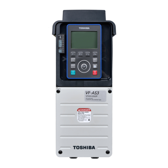
Toshiba TOSVERT VF-AS3 Instruction Manual
Rs485 communication function
Hide thumbs
Also See for TOSVERT VF-AS3:
- Instruction manual (622 pages) ,
- Manual (69 pages) ,
- Quick start manual (68 pages)
Advertisement
Quick Links
RS485 Communication Function
Instruction Manual
1. Make sure that this instruction manual is received by those who actually uses the
RS485 communication function.
2. Read this manual thoroughly before using the RS485 communication function. After
reading this manual, keep it in a safe place for future maintenance and inspection.
3. The information in this manual is subject to change without prior notice.
Attention
E6582143
I
Safety precautions
II
III
1
Communication
function overview
2
Transmission
specifications
3
RS485 communication
wiring diagram
4
Selecting
communication protocol
5
TOSHIBA
inverter protocol
6
MODBUS-RTU
protocol
7
Inverter-to-inverter
communication ([F806]
or [F826])
8
Communication-
related parameters
9
Control through
communication
10
Parameter data
A1
<Appendix 1> Data
code table
A2
<Appendix 2>
Response time
A3
<Appendix 3> Inverter
type (FB05)
A4
<Appendix 4>
Troubleshooting
15
16
17
18
Advertisement

Summary of Contents for Toshiba TOSVERT VF-AS3
- Page 1 E6582143 Safety precautions Communication function overview Transmission specifications RS485 communication wiring diagram Selecting communication protocol RS485 Communication Function TOSHIBA inverter protocol Instruction Manual MODBUS-RTU protocol Inverter-to-inverter communication ([F806] or [F826]) Communication- related parameters Control through communication Parameter data <Appendix 1> Data code table <Appendix 2>...
- Page 3 Safety precautions The items described in the instruction manual and on the inverter itself are very important so that you can use safely the inverter, prevent injury to yourself and other people around you as well as to prevent damage to property in the area. Thoroughly familiarize yourself with the safety precautions in the inverter instruction manual (E6582062) and then continue to read the manual.
- Page 4 [10.Parameter data]) have only RAM but no EEPROM, so there is no limit to the number of writing times. -> Refer to [5. 2 When TOSHIBA inverter protocol is used and if there is no need to store Transmission Mandatory data, you can write only to RAM (using a P command).
- Page 5 4. 1 Reception frame completion process ......................4-1 TOSHIBA inverter protocol ............................. 5-1 5. 1 TOSHIBA inverter protocol transmission format ..................... 5-2 5. 1. 1 ASCII mode transmission format ...................... 5-2 5. 1. 2 Binary mode transmission format ..................... 5-5 5.
- Page 6 E6582143 Parameter data ..............................10-1 <Appendix 1> Data code table ..........................A1-1 <Appendix 2> Response time ..........................A2-1 <Appendix 3> Inverter type (FB05) ........................A3-1 <Appendix 4> Troubleshooting ..........................A4-1 VF-AS3...
- Page 7 (hereinafter referred to as computer) and the inverter by connecting the optional USB communication conversion unit (USB001Z). Available communication protocols are TOSHIBA inverter protocol and MODBUS-RTU protocol. You can set which protocol to use in [F807: RS485 (1) protocol] or [F827: RS485 (2) protocol].-> Refer to [4.
- Page 8 E6582143 <Computer link function> Regardless of using TOSHIBA inverter protocol or MODBUS-RTU protocol, you can pass on the following information to the computer by creating a program according to the procedures described later. (1) Monitoring inverter status (such as the output frequency, current, and voltage)
- Page 9 Stop bit length Received by inverter: 1bit/Sent by inverter: 2 bits Error detecting Parity: Even/Odd/Non parity (selectable using a parameter) scheme Checksum (TOSHIBA inverter protocol), CRC (MODBUS-RTU) Character 11-bit characters (Stop bit =1, with parity) transmission format Order of bit...
- Page 11 RS485 communication wiring diagram CAUTION • Do not connect Ethernet to the RS485 communication connector. Incorrect wiring can result in malfunction. Prohibited ■ RS485 communication connector 1 1 pin 8 pin RS485 communication connector 1 Signal name Pin arrangement Description RXA+/TXA+ Non-inverting transmitted and received data RXB-/TXB-...
- Page 12 E6582143 ■ Wiring example Straight Straight Straight Slave Slave Master Slave 4 pin RXA+/TXA+ RXA+/TXA+ RXA+/TXA+ RXA+/TXA+ 5 pin RXB-/TXB- RXB-/TXB- RXB-/TXB- RXB-/TXB- 8 pin (3 pin) Line terminations resistor Pull-up/pull-down resistor 120 Ω - 1/2 W 510 Ω - 1/2 W * Do not connect the 7 pin (power).
- Page 13 E6582143 ■ RS485 communication connector 2 8 pin 1 pin RS485 communication connector 2 (RS485COM2) Signal name 2-wire 4-wire Description arrangement [F829] = "0" [F829] = "1" RXA+/TXA+ Non-inverting transmitted and received data Non-inverting received data RXB-/TXB- Inverting transmitted and received data Inverting received data Non-inverting transmitted data Inverting transmitted data...
- Page 14 E6582143 ■ Wiring example for 2-wire Straight Straight Straight Slave Slave Master Slave 4 pin RXA+/TXA+ RXA+/TXA+ RXA+/TXA+ RXA+/TXA+ 5 pin RXB-/TXB- RXB-/TXB- RXB-/TXB- RXB-/TXB- 8 pin Line terminations resistor Pull-up/pull-down resistor 120 Ω - 1/2 W 120, 510 Ω - 1/2 W Cautions for wiring - To use RS485 in 2-wire, set [F829: RS485 (2) wiring type] to "0: 2-wire."...
- Page 15 E6582143 ■ Recommended parts Recommended cable : Balanced twisted pair cable with the minimum conductor size of AWG24 (0.22 mm ) and a characteristic impedance of 100 to 120Ω Recommended connector : RJ45 modular plug VF-AS3 3. RS485 communication wiring diagram...
- Page 17 Selecting communication protocol Supported communication protocols are TOSHIBA inverter protocol and part of MODBUS-RTU protocol. Select the protocol in [F807: RS485 (1) protocol] or [F827: RS485 (2) protocol]. Communication Title Parameter name Adjustment range Default setting F807 0807 RS485 (1) protocol...
- Page 19 TOSHIBA inverter protocol Set [F807: RS485 (1) protocol] or [F827: RS485 (2) protocol] to "0: TOSHIBA." In the default setting, both [F807] and [F827] are set to "0: TOSHIBA."-> Refer to [4. Selecting communication protocol] CAUTION • Set the parameter of communication time-out The devices cannot be stopped when a communication error occurs.
- Page 20 E6582143 5. 1 TOSHIBA inverter protocol transmission format 5. 1. 1 ASCII mode transmission format Specify data with a communication number, and describe the data format in hexadecimal and character transmission with JIS-X-0201 (ASCII (ANSI)). ■ Computer -> inverter Omittable for one-to-one communication...


