Table of Contents
Advertisement
Quick Links
Advertisement
Table of Contents

Related Manuals for BKT Elektronik EMS

Summary of Contents for BKT Elektronik EMS
- Page 1 BKT Elektronik - Headquarter Poland, Lochowska 69 Str. 86-005 Biale Blota Phone: +48 52 36 36 750 e-mail: export@bkte.pl BKT EMS Environmental Monitoring System - the environmental parameters monitoring system - installation and configuration manual - version 7 © 2022 BKT Elektronik...
-
Page 2: Table Of Contents
4.8 Installation of accessories ................................29 4.8.1 EA313 - 30V/5A relay ............................... 29 4.8.2 EA315 - light signal ................................31 4.9 An example of placing devices in the cabinet ..........................32 BKT EMS - installation and configuration instructions for the environmental parameters monitoring system... - Page 3 5.17.11 FTP backup settings ................................. 63 5.17.12 VPN client settings................................63 5.17.13 SMTP settings .................................. 64 5.18 System menu (system management) .............................. 64 5.18.1 Restoring default settings through a website........................64 BKT EMS - installation and configuration instructions for the environmental parameters monitoring system...
- Page 4 The specification is owned and copyrighted by BKT Elektronik Sp. z o.o. Information contained herein may be changed at owner’s discretion without any notice. BKT Elektronik may not be held liable for any possible inaccuracies and discrepancies in this document.
-
Page 5: Overview
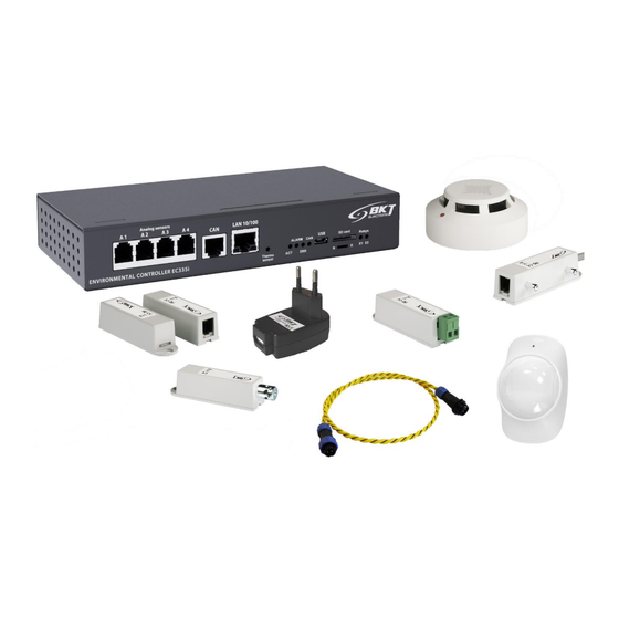
OVERVIEW The BKT EMS system is designed to monitor environmental parameters (temperature, humidity, etc.) in a telecommunications cabinet or small rooms. Its purpose is to warn users about possible emergency situations and report any failures. The single system controller can support: up to 4 analogue sensors, 4 sensors with potential-free contacts and two signalling devices. - Page 6 Connectors: 15m long cable from the casing, terminated with a RJ14 (6P4C) plug, maximum allowed length of a connection cable: 100m Dimensions: 7x30 + 15 m cable BKT EMS - installation and configuration instructions for the environmental parameters monitoring system...
-
Page 7: Can Digital Sensors
Possibility to connect up to 10 devices in a daisy chain (sensor has 2 CAN ports); Power consumption: 1000mW Connectors: 2x RJ12 socket of CAN bus Cable: RJ12(6P4C)-RJ12(6P4C), included 2m, maximum allowed length of CAN bus: 200m; Dimensions: 100x45 BKT EMS - installation and configuration instructions for the environmental parameters monitoring system... -
Page 8: Extension Modules And Accessories
Flashing frequency: 1Hz Power supply 12V, 80mA Connectors: 1x 2pin terminal block Cable: 1.5m 2-wire cable included Dimensions: 73x45 EA316 – 1U 19’’ bracket for 3xEE321 122EA003160 Dimensions: 482x44x80 BKT EMS - installation and configuration instructions for the environmental parameters monitoring system... -
Page 9: System Structure
EE322 extension modules. It should be assumed that each sensor with a potential-free output loads the controller as much as 0.5 analogue sensor. BKT EMS - installation and configuration instructions for the environmental parameters monitoring system... -
Page 10: Example 1. Extension Modules Ee321
Sensors with potential-free contacts connected directly to the controller 2 (in real 4) Sensors with potential-free contacts connected via EE322 extension modules 32 (in real 64) Total BKT EMS - installation and configuration instructions for the environmental parameters monitoring system... -
Page 11: Example 3. Can Devices
Analogue sensors connected via EE321 extension modules ES340 CAN sensors (temperature, humidity, smoke) 18 (6x3) Sensors with potential-free contacts connected via EE322 extension modules 16 (in real 32) Total (over suggested 60) BKT EMS - installation and configuration instructions for the environmental parameters monitoring system... -
Page 12: Example 4. It Cabinet Monitoring
Sensor type Number of sensors as a load for the controller Analogue sensors connected directly to the controller ES340 CAN sensors (temperature, humidity, smoke) 18 (6x3) Total BKT EMS - installation and configuration instructions for the environmental parameters monitoring system... -
Page 13: Installation Of Devices
USB plug – USB A – 4pcs. block – 1pc. block – 1pc. block – 1pc. 1A – 1pc. socket – 1pc. 4.1.2 Controller dimensions 4.1.3 1U 19’’ bracket installation BKT EMS - installation and configuration instructions for the environmental parameters monitoring system... -
Page 14: Device Connectors
CAN – CAN bus status LED 13. Controller reboot button Installation of EA319i – LTE modem 4.2.1 Package contents Module pcb board Antenna – 2pcs. – 1pc. BKT EMS - installation and configuration instructions for the environmental parameters monitoring system... -
Page 15: Assembly Procedure
To remove the card, push it in again until it clicks. 1. SMA socket for GSM antenna 2. LED, blinks when modem is powered 3. microSIM card slot 4. SMA socket for GSM antenna BKT EMS - installation and configuration instructions for the environmental parameters monitoring system... -
Page 16: Installation Of Ee321 Module - 8 Analogue Inputs Extension
EE321 module – Power supply RJ14(6P4C)- Self-adhesive foot – Cable 1szt. 230VAC, 12VDC 1A 4pcs. RJ14(6P4C), 2m – 1pc. – 1pc. 4.3.2 EE321 dimensions 4.3.3 1U 19’’ bracket installation BKT EMS - installation and configuration instructions for the environmental parameters monitoring system... -
Page 17: Device Connectors
Switches: FR - firmware update and TR – bus terminator (see in the table 4.3.5 Connecting the EE321) CAN bus connectors Signal LEDs (see in table 4.3.5 Connecting the EE321) BKT EMS - installation and configuration instructions for the environmental parameters monitoring system... -
Page 18: Connecting The Ee321 Module
The FR switch is for servicing and must be in OFF position during normal operation. FR-off, TR-on FR-off, TR-off BKT EMS - installation and configuration instructions for the environmental parameters monitoring system... -
Page 19: Installation Of Ee322 Module- Extension Of 32 Inputs For Voltage-Free Contacts
EE322 module – 1pc. Cable Self-adhesive foot 6-pin terminal M3x8 bolts – 6pcs. 1U 19’’ bracket - RJ14(6P4C)- – 4pcs. block– 1pc. 2pcs. RJ14(6P4C), 2m – 1pc. 4.4.2 EE322 dimensions BKT EMS - installation and configuration instructions for the environmental parameters monitoring system... -
Page 20: 19'' Bracket Installation
3.LED indicating connection error with the EC335i controller 4. CAN bus inputs 5. FR switches - firmware update and TR - bus terminator (see in the table 4.4.5 Connecting the EE322 module) BKT EMS - installation and configuration instructions for the environmental parameters monitoring system... -
Page 21: Connecting The Ee322 Module
CAN bus. A way to connect voltage-free contacts to the EE322 module. For CAN bus connections, use UTP cat5e cable terminated with RJ14 (6P4C) - RJ14 plugs (6P4C). BKT EMS - installation and configuration instructions for the environmental parameters monitoring system... -
Page 22: Installation Of Es340 Sensor - Smoke, Humidity, Temperature
1 – CAN bus terminator disabled 2 – CAN bus terminator enabled. Only the last device on the CAN bus should have a jumper in position 2. BKT EMS - installation and configuration instructions for the environmental parameters monitoring system... - Page 23 BKT EMS - installation and configuration instructions for the environmental parameters monitoring system...
-
Page 24: Installation Of Es341 Sensor - Pressure, Humidity, Temperature
CAN bus connectors. For CAN bus connections, use the original 4-core cable or UTP cat5e terminated with RJ14 (6P4C) -RJ14 (6P4C) plugs. Dimensions of the ES341 sensor BKT EMS - installation and configuration instructions for the environmental parameters monitoring system... -
Page 25: Installation Of Analogue Sensors
100m. The sensor should be connected to one of the analogue inputs of the controller or the EE321 extension module. BKT EMS - installation and configuration instructions for the environmental parameters monitoring system... -
Page 26: Es353 - Door Sensor
To avoid false alarms, the mounting location should be chosen Base of the accordingly: - away from ventilation openings, dusty places, smoky detector areas, etc. Detector BKT EMS - installation and configuration instructions for the environmental parameters monitoring system... -
Page 27: Es357 - Pir Sensor
The ES357 detector has a cable permanently connected to the detector, which should be connected to the analogue input of the controller. This cable can be extended to a maximum of 50m. BKT EMS - installation and configuration instructions for the environmental parameters monitoring system... -
Page 28: Es359 - Point Leak Sensor
ES368 water sensitive cable using the terminal block provided. Rear Front ES361 – water ES360 – leak sensor for sensitive cable water sensitive cable BKT EMS - installation and configuration instructions for the environmental parameters monitoring system... -
Page 29: Es362 - 4-20Ma Current Sensor
5.5mm or adhesive double-sided tape. For mounting in IT cabinets, use a cage nuts and bolts with M4 or M5 size. BKT EMS - installation and configuration instructions for the environmental parameters monitoring system... - Page 30 It protects the contacts of the relay against overvoltage. 1N4007 Inductive load BKT EMS - installation and configuration instructions for the environmental parameters monitoring system...
-
Page 31: Ea315 - Light Signal
The light signal should be connected to one of the controller voltage outputs. Use the attached wire or cable with a cross-section of 1mm The maximum length of the connecting cable should not exceed 100m. BKT EMS - installation and configuration instructions for the environmental parameters monitoring system... -
Page 32: An Example Of Placing Devices In The Cabinet
EE322 – extension of 32 inputs for voltage-free contacts EC335i – controller ES351 – humidity sensor ES352 – 230VAC voltage sensor ES350 – temperature sensor at the bottom of the cabinet BKT EMS - installation and configuration instructions for the environmental parameters monitoring system... -
Page 33: Configuration
View of sensotr parameters against the room layout. User management. Configuration of extension modules. Displaying sensor values on charts. Resetting the smoke sensors following an alarm. System settings. Firmware update and data export. BKT EMS - installation and configuration instructions for the environmental parameters monitoring system... -
Page 34: Saving Settings Into Non-Volatile Memory
- add element to the template - save template - end template editing General statistics Select Overall Stats from the vertical menu to display basic data on the system status. BKT EMS - installation and configuration instructions for the environmental parameters monitoring system... -
Page 35: System Tree (System Components)
To maintain proper performance of the device, it is recommended to use max 200 components in the system. To maintain the settings after restarting the controller, write them to non-volatile memory. BKT EMS - installation and configuration instructions for the environmental parameters monitoring system... - Page 36 Add Modbus RTU write query (not applicable) Add Modbus TCP read query Add Modbus TCP write query Add mathematical sensor Add IP camera Add virtual dew point sensor BKT EMS - installation and configuration instructions for the environmental parameters monitoring system...
-
Page 37: Setting The Sensor Parameters
1 minute), 100 hours (reading every 1h) and 100 days (reading every 1 day) are available. It is possible to export this data to xml or csv files. BKT EMS - installation and configuration instructions for the environmental parameters monitoring system... -
Page 38: Adding A New Group
It is recommended to add individual elements (sensors) to a group rather than entire modules, as notifications are then more precise. They apply to a single sensor, not the entire module. BKT EMS - installation and configuration instructions for the environmental parameters monitoring system... -
Page 39: Adding An Email Notification
Dynamic variables: Definition of logic scheme (see chapter 5.10 Logical schemes) or name of the group generating the notification (see chapter 5.6.2 Adding a new group). BKT EMS - installation and configuration instructions for the environmental parameters monitoring system... -
Page 40: Adding A Trap Notification
In order for the notification to be sent during an alarm, it should be placed in a logic scheme diagram (see chapter 5.10 Logical schemes) or in a group notification (see chapter 5.6.2 Adding a new group). BKT EMS - installation and configuration instructions for the environmental parameters monitoring system... -
Page 41: Adding An Sms Notification
In order for the notification to be sent during an alarm, it should be placed in a logic scheme diagram (see chapter 5.10 Logical schemes) or in a group notification (see chapter 5.6.2 Adding a new group). BKT EMS - installation and configuration instructions for the environmental parameters monitoring system... -
Page 42: Adding Web Sms Notification
The user's password is encrypted with the SHA-1 algorithm $PHONES$ The telephone number of the SMS recipient from the Phone number field $MESSAGE$ Message text from the Message text field BKT EMS - installation and configuration instructions for the environmental parameters monitoring system... -
Page 43: Adding Sms Gate Notification
It is also possible to get the user's attention by making a call to him. It is only a ringing tone. The device does not have a voice communicator, e.g. playing a voice message. BKT EMS - installation and configuration instructions for the environmental parameters monitoring system... -
Page 44: Adding Http Notification
User password encrypted with the MD5 algorithm $PASSWORD_SHA1$ The user's password is encrypted with the SHA-1 algorithm $RECIPIENT Server address from Recipient field $MESSAGE$ Message text from the Message field BKT EMS - installation and configuration instructions for the environmental parameters monitoring system... -
Page 45: Adding A Timer
In logic diagrams (see chapter 5.10 Logical schemes) or in notifications for groups (see chapter 5.6.2 Adding a new group), you can define e.g. sending an alarm email when the external device stops responding to PING. BKT EMS - installation and configuration instructions for the environmental parameters monitoring system... -
Page 46: Adding An Snmp Get
Polling period (sec.) The frequency of sending queries to the device being polled (in seconds). OID identifier The identifier of the SNMP variable in the format „.1.3.6.1.2.1.1.3.0”. BKT EMS - installation and configuration instructions for the environmental parameters monitoring system... -
Page 47: Adding Modbus Tcp Element
Type of the date being polled. Available: unsigned and signed 16 bit and 32 bit word, 32 bit float value. Data order The order of reading bytes from the register. Polling period (sec.) The frequency of sending queries to the device being polled (in seconds). BKT EMS - installation and configuration instructions for the environmental parameters monitoring system... -
Page 48: Adding Virtual Mathematical Element
"x" before comparison with the alarm thresholds. The expression can contain the following characters: operators: "+", "-", "*", "/", "%" (the remainder), "^" (exponentiation); functions: "abs()","sqrt()","exp()","ln()","log()","sin()","cos()","tan()","asin()","acos()","atan()"; constants: "pi" (3.1415926...), "e" (2.7182818...) BKT EMS - installation and configuration instructions for the environmental parameters monitoring system... -
Page 49: Adding A Camera
Threshold for low value warning. High warning level Threshold for high value warning High alarm level Threshold for high value alarm. Hysteresis type Please see 5.6.1 Setting the sensor parameters BKT EMS - installation and configuration instructions for the environmental parameters monitoring system... -
Page 50: Dry Contacts (Binary Inputs For Potential-Free Contacts)
In the case of prepaid phones, you can enter the balance inquiry code here or any other USSD code. (USSD code) Clear SMS list Clears the list of sent text messages. BKT EMS - installation and configuration instructions for the environmental parameters monitoring system... -
Page 51: Event Log
In order for the settings to be kept after restarting the controller, they should be saved to non-volatile memory. BKT EMS - installation and configuration instructions for the environmental parameters monitoring system... - Page 52 CONTROLLER\n CONTROLLER %5{201001}-%7{201001}°C-%6{201001}\n 'Onboard-Temperature'-'27.80'°C-'normal' %5{203001}-%7{203001}V-%6{203001}\n 'Onboard-Voltage DC'-'12.00'V-'normal' SERVER ROOM\n SERVER ROOM %5{107001}-%6{107001}\n 'Leak under raised floor'-'normal' %5{201006}-%7{201006}°C-%6{201006}\n 'Cab_GPD__temp_dn'-'23.06'°C-'normal' %5{201023}-%7{201023}°C-%6{201023}\n 'Cab_GPD__temp_up'-'24.50'°C-'normal' %5{202009}-%7{202009}%-%6{202009}\n 'Cab _GPD__humi'-'27.00'% 'normal' %5{106009}-%6{106009}\n 'Cab _GPD__smoke'-'normal' BKT EMS - installation and configuration instructions for the environmental parameters monitoring system...
-
Page 53: Cameras
Select Users from the vertical menu to manage system users, create new users, remove users and grant rights. Click the ‘+’ button in the horizontal menu to add a new user. BKT EMS - installation and configuration instructions for the environmental parameters monitoring system... - Page 54 The last tab allows you to grant read and/or write permissions to individual groups of elements defined in chapter 5.6.2 Adding a new group. To maintain the settings after restarting the controller, write them to non-volatile memory. BKT EMS - installation and configuration instructions for the environmental parameters monitoring system...
-
Page 55: Can Configuration (Extension Module)
CAN flashes – the CAN bus is active, but there is no communication with the extension module. CAN is on – the CAN bus is active and there is communication with the extension module. BKT EMS - installation and configuration instructions for the environmental parameters monitoring system... -
Page 56: Graphs
• temperature unit (Celsius or Fahrenheit degrees) • default start page • activate an acoustic signal via the website when the alarms are active BKT EMS - installation and configuration instructions for the environmental parameters monitoring system... -
Page 57: Network Settings
Enable logging of LTE connection status. Use this feature only for debugging when setting up a connection. During normal operation, logging should be turned off. Save log to disk Button to download LTE logs. BKT EMS - installation and configuration instructions for the environmental parameters monitoring system... -
Page 58: Time Settings
The values read from the sensors are saved on the USB drive in csv files. Direct access path to data on the SD card: http://{login}:{pass}@192.168.0.101/sdcard/ Direct access path to data on the USB drive: http://{login}:{pass}@192.168.0.101/usbflash/ BKT EMS - installation and configuration instructions for the environmental parameters monitoring system... -
Page 59: Sending Logs And Sensor Values To Ftp, Mail
The device also allows transfer only system events to the SYSLOG server. Select Preferences->Logging-> Syslog 5.17.8 DynDNS settings The DynDNS (www.dynDNS.com) or no-IP (www.no-ip.org) services can be used with the device. Select Preferences→DynDNS from the vertical menu. BKT EMS - installation and configuration instructions for the environmental parameters monitoring system... -
Page 60: Snmp Settings
– details of CAN sensors ctlCANSensorsDiscretsTable - inputs for potential-free contacts ctlCANSensorsAnalogsTable - analogue sensors ctlCANSensorsOutletsTable – output modules (relays) ctlRsSensors – not available in current firmware BKT EMS - installation and configuration instructions for the environmental parameters monitoring system... - Page 61 – output modules (relays) of CAN modules. Example of query for a temperature sensor installed inside the controller The required temperature sensor in the system tree. Identifier of required sensor. BKT EMS - installation and configuration instructions for the environmental parameters monitoring system...
- Page 62 Hysteresis type (value – hysteresis enabled) .1.3.6.1.4.1.47394.5.2.1.18.201999 ctlInternalSensorsAnalogHystValue.201999 0.30 Hysteresis value (0.30°C) .1.3.6.1.4.1.47394.5.2.1.19.201999 ctlInternalSensorsAnalogValueInt.201999 2860 Inteager value read from the element (sensor) (sensor value .1.3.6.1.4.1.47394.5.2.1.25.201999 multiplied by 100) BKT EMS - installation and configuration instructions for the environmental parameters monitoring system...
-
Page 63: 5.17.10 Radius Settings
VPN client settings The device uses the OpenVPN library to provide a VPN client. The service configuration is available after selecting Preferences-> VPN Client from the vertical menu. BKT EMS - installation and configuration instructions for the environmental parameters monitoring system... -
Page 64: 5.17.13 Smtp Settings
Select System menu→About from the vertical menu and click OK Confirm to restart the device and wait until the restarting process is next to Reboot the system. completed. BKT EMS - installation and configuration instructions for the environmental parameters monitoring system... -
Page 65: Firmware Update
If you are updating remotely and are unable to observe the LED indicator, do not refresh the page for more than a few minutes. BKT EMS - installation and configuration instructions for the environmental parameters monitoring system... -
Page 66: Export Data To A File
Start of the setting restoration process is indicated by the ERROR light, whereas successful completion of the same is indicated by the ACT light flashing. Restart is restarting. Remove pendrive The device settings have been restored from the file. BKT EMS - installation and configuration instructions for the environmental parameters monitoring system... -
Page 67: Quick Start Guide
The default settings have been restored. Start configuring the device when the ACT LED starts blinking. Default settings IP address 192.168.0.101 Network mask 255.255.255.0 Network gate 192.168.0.1 DNS server 192.168.0.1 DHCP client Disabled Passwords User: guest; password: guest BKT EMS - installation and configuration instructions for the environmental parameters monitoring system... -
Page 68: Initial Configuration
Use the displayed wizard for initial configuration. Choose the interface language. Set the date and time. If necessary, change the network settings. If necessary, change the SNMP protocol communication settings. BKT EMS - installation and configuration instructions for the environmental parameters monitoring system... -
Page 69: Identification Of The Controller Ip Address
The following procedure allows you to quickly configure email notifications about changes in the status of sensors installed in the system. Select System tree in the vertical menu. Click on individual sensors visible in the system that require renaming or adjusting the default assigned alarm thresholds. BKT EMS - installation and configuration instructions for the environmental parameters monitoring system... - Page 70 (up to 10 in one notification). The text of the message does not need to be changed, it can remain the default. Confirm the changes. For more information, see 5.6.3 Adding an email notification. BKT EMS - installation and configuration instructions for the environmental parameters monitoring system...
- Page 71 From the Notifications tab, move the previously configured email notification to the right window. Check the types of sensor status changes you want to be informed about. Confirm the changes. BKT EMS - installation and configuration instructions for the environmental parameters monitoring system...
-
Page 72: Document Revisions
EC335 controller in a new housing. Hardware part has been extended - assembly and connection of February 2019 devices The device configuration description has been extended May 2019 Updated with new software functionalities 2.8.2b177 September 2020 New controller version EC335i October 2022 BKT EMS - installation and configuration instructions for the environmental parameters monitoring system...
Need help?
Do you have a question about the EMS and is the answer not in the manual?
Questions and answers