Table of Contents
Advertisement
Quick Links
Advertisement
Table of Contents

Subscribe to Our Youtube Channel
Related Manuals for Kaye Validator AVS


Summary of Contents for Kaye Validator AVS
- Page 1 Validation ® Kaye Validator User’s Manual Kaye Validator User’s Manual...
- Page 2 ® Kaye Validator Thermal Process Validation System User’s Manual M5100-EN Rev. A May 2015...
- Page 3 [No content intended for this page] Kaye Validator User’s Manual...
-
Page 4: Table Of Contents
Chapter 1. The Kaye Validator Introduction ........................1 Validator Benefits ......................3 About this Manual ......................4 The Kaye Validator System ................... 5 1.4.1 The Validator Hardware ..................5 1.4.2 Sensor Input Modules (SIMs) ................6 1.4.3 Plug-In Hardware Connections ................7 The Validator Software .................... - Page 5 Apply an Existing Setup ....................65 The Define Setup Screen ..................... 65 The Sensors Configuration Screen ................67 Understanding Groups ....................70 Assigning Sensors to Groups ..................71 Specifying Group Calculations ..................73 Specifying Calibration Parameters ................74 Kaye Validator User’s Manual...
- Page 6 Changing the IRTD Address ..................98 Chapter 9. The Qualification Study Introduction ........................99 Load a Setup ....................... 101 9.2.1 Select a Setup File................... 101 Viewing the Active Qualification Study ..............104 Graph Real-Time Sensor Readings and Calculations ..........106 Kaye Validator User’s Manual...
- Page 7 B.1 Waste Electrical and Electronic Equipment (WEEE) Directive........ 151 B.2 Battery Disposal ......................152 B.2.1 What do the Markings Mean? ................ 152 B.2.2 The Risks and Your Role in Reducing Them ..........153 Appendix C. Safety and Precautions Appendix D. Service information Kaye Validator User’s Manual...
-
Page 8: Chapter 1. The Kaye Validator
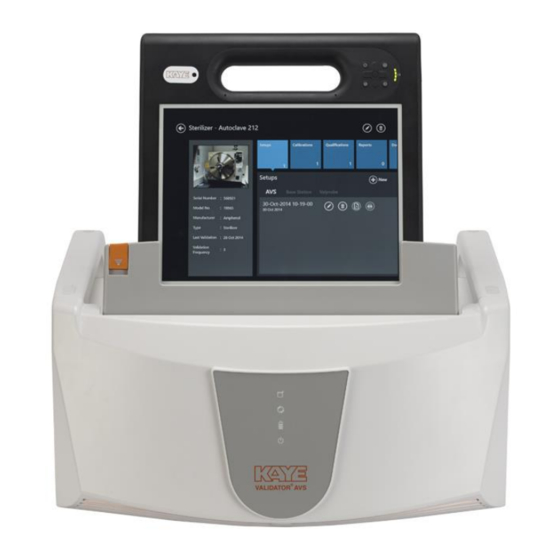
Chapter 1. The Kaye Validator Introduction Figure 1: The Kaye Validator The Kaye Validator® system is a validation system designed for thermal process validation in the pharmaceutical and biotechnology industries. It features automated sensor calibration and qualification reporting. A complete Kaye® validation package, which lets you perform a fully automated sensor calibration, includes: ... - Page 9 Chapter 1. The Kaye Validator Up to four Kaye Sensor Input Modules (SIMs) per Validator (each SIM supplies up to 12 sensors) A Kaye high temperature reference (HTR 400), a Kaye low temperature reference (LTR –90, LTR –25/140 or LTR –40/140), or a Kaye cold temperature reference (CTR –40 or CTR –80) for sensor calibration and verification...
-
Page 10: Validator Benefits
Chapter 1. The Kaye Validator Validator Benefits The Kaye Validator brings important benefits to the validation process: Designed to help meet FDA guidelines for protecting electronic data (21 CFR Part 11) Fully validated software, hardware, and firmware ... -
Page 11: About This Manual
Chapter 3 provides instructions for creating user accounts. Chapter 4 provides instructions for entering Kaye equipment into the system. Chapter 5 provides instructions for entering customer assets into the system. Chapter 6 provides instructions for creating setups. -
Page 12: The Kaye Validator System
24 RTD inputs. The instrument is equipped with a universal power supply (100-240 VAC) and connections for two Kaye temperature standards (although only one standard can be used at any given time), one Kaye temperature reference, a USB cable and a contact output for signaling a PLC or other device The Validator includes a built-in USB flash drive interface for collecting data after the completion of a study and a tablet PC for viewing data. -
Page 13: Sensor Input Modules (Sims)
Chapter 1. The Kaye Validator 1.4.2 Sensor Input Modules (SIMs) The Validator uses Sensor Input Modules to provide secure connection of sensors to the Validator while protecting the electronics from draft, dust, humidity, electrical noise and mechanical shock. SIMs are designed to be wired once and used repeatedly. You can wire SIMs yourself, or buy pre-wired SIMs to reduce preparation time. -
Page 14: Plug-In Hardware Connections
Chapter 1. The Kaye Validator 1.4.3 Plug-In Hardware Connections The Validator has connectors on the back of the unit for easy plug-in of SIMs, temperature standards, temperature references, a USB cable, and a USB memory card on the left side of the instrument. -
Page 15: The Validator Software
Chapter 1. The Kaye Validator The Validator Software The Validator software provides everything you need to perform validation testing. Using the Validator software, you: • Create user accounts and assign user IDs, passwords and permission levels. • Create validation study setups that can be run standalone on the Validator or from a Console. -
Page 16: Electronic Data Requirements
Chapter 1. The Kaye Validator 1.5.3 Electronic Data Requirements The Validator is designed to help you meet the guidelines for electronic signatures as specified in FDA Regulation 21 CFR part 11, Electronic Records; Electronic Signatures. • Two levels of identification - user ID and password •... - Page 17 Chapter 1. The Kaye Validator • Specify start and stop conditions for the qualification cycle and the exposure cycle • Specify how often to scan sensors • Define the output relay After you have created and saved your setup, you run the study by loading the setup into the Validator via connection from your Console to the Validator.
-
Page 18: Sensor Calibration
Validator software. If your validation system includes a Kaye temperature reference and a Kaye IRTD, you can perform fully automatic pre-qualification and post-qualification calibrations. If you do not have a Kaye temperature reference you can manually set your reference. Standalone calibration requires a Kaye temperature reference and a Kaye IMPORTANT: IRTD. -
Page 19: The Qualification Study
Chapter 1. The Kaye Validator 1.5.6 The Qualification Study During a qualification study, the Validator performs calculations and compiles data for your reports. You can run the qualification study in standalone mode or from the Console using the Validator software. -
Page 20: Using The Validator System
Chapter 1. The Kaye Validator 1.6 Using the Validator System The Validator system allows you the flexibility to design your qualification procedures to fit your workplace requirements. To perform a typical qualification study, it is recommended to follow the following steps in order: 1. - Page 21 Chapter 1. The Kaye Validator 1.6 Using the Validator System (cont.) The Validator collects all study data and stores it in a secure data file internally, on USB flash, and in your Console’s memory. 7. With the secure data file loaded on your Console, use the Validator software to design and generate reports to document the specifics of your study.
-
Page 22: Chapter 2. The Validator Hardware
Chapter 2. The Validator Hardware Introduction The Kaye Validator comes equipped with a universal power supply, a power cord for 115 VAC (or 230 VAC as necessary), over 4 GB of internal memory, and a USB flash drive interface. This chapter describes the Validator hardware and provides instructions for connecting the system. -
Page 23: The Validator Instrument
Each connection port is labeled with an icon representing its function. The connection ports are defined on page 18. Below the ports are the ON/OFF switch and the AC power input. Figure 5: Connection Ports Kaye Validator User’s Manual... -
Page 24: Symbol Identification
Connection Port 4 Pin Din Connector There are three 4-pin Din connectors, labeled with a temperature reference icon, for connecting IRTDs and one Kaye temperature reference. (Note: The Validator can accept data from only one IRTD at any given time.) -
Page 25: Side Port For Data Transfer
Validator software. Files that have been tampered with are no longer readable by the software. Figure 6: Side Port for Data Transfer Kaye Validator User’s Manual... -
Page 26: The Console
2.2.4 The Console For programming and control, each Validator includes a Windows 8.1-based Console Figure below shows the procedure for docking a Console to a Validator via its docking station. Figure 7: Docking and Releasing Console Kaye Validator User’s Manual... -
Page 27: Internal Memory
24 Channels per second in 3 36 Channels per second in 3 SIMs SIMs (8 channel/SIM) (12 channel/SIM) 32 Channels per second in 4 36 Channels per second in 4 SIMs SIMs (8 channel/SIM) (9 channel/SIM) Kaye Validator User’s Manual... - Page 28 IMPORTANT: If 8 inputs/second is selected, the file rate for 36-48 thermocouple sensors is 2 seconds due to overhead processing. When you create a setup, you select the file rate from a list of valid rates. Kaye Validator User’s Manual...
-
Page 29: Backup Battery
“memory” effect inherent in lithium ion batteries, it is a good practice to completely discharge and recharge the lithium ion battery on a periodic basis. The unit is equipped with rechargeable battery pack (RRC2040-2) Kaye Validator User’s Manual... - Page 30 2. Turn the power switch on. 3. Let the unit run for 3 hours to fully charge the battery. A replacement battery pack is available. CAUTION! Batteries must be disposed of in accordance with local, state and federal regulations. Kaye Validator User’s Manual...
-
Page 31: Sensor Input Modules
SIMs, and power up again. If a SIM is disconnected after power up, that SIM's sensors will be read as Open and no data will be recorded for that SIM. To rectify this, power down, reconnect the SIM, and power back up. Kaye Validator User’s Manual... -
Page 32: Wiring Sims
Sensor location number. There are 12 connection locations, labeled 1 - 12, with a positive and negative connector for each input. 2. Press the two press-keys to open connectors where the sensor is to be inserted. Kaye Validator User’s Manual... - Page 33 8. Label the SIM with SIM slot number, SIM serial number, the Validator serial number, and the calibration date. Note: To wire the dedicated 4-20 mA SIM, see document Z2036, “4 to 20 mA Sensor Input Module.” Kaye Validator User’s Manual...
- Page 34 SIM. To add a drip cut, remove 4 inches (10 cm) of the outer insulation from each thermocouple at a point where natural drainage can take place without water reaching the terminal screws (see Figure 11 below). Figure 11: Drip Cut Kaye Validator User’s Manual...
- Page 35 Figure 12 below. Figure 12: Shaving from Inner Wire Jackets If moisture does collect in the SIM, remove the SIM from the instrument, open, and allow to air dry before storage. Kaye Validator User’s Manual...
- Page 36 Always connect the positive (+) lead to the positive (+) connector and the negative (-) lead to the negative (-) connector. + – + – + – + – + – + – Voltage – Transducer Figure 14: Voltage Input Connection Kaye Validator User’s Manual...
-
Page 37: Kaye Irtd
Figure 15: Current Transmitter Connection Kaye IRTD The Kaye IRTD temperature measurement standard is a self-contained measurement system providing temperature data directly to the Validator software. The measurement accuracy is NIST-traceable to 0.025ºC, with a range of 183ºC to 420ºC. -
Page 38: Temperature Reference
The CTR -80 accepts up to 36 thermocouples. CTR -40 (setpoint range -40°C to 150°C) Recommended for calibration of sensors used in freezers, cold rooms, incubators and steam autoclaves. The CTR -40 accepts up to 36 thermocouples. Kaye Validator User’s Manual... - Page 39 The Kaye LTR-90, LTR -25/140, LTR -40/140, and the HTR 400 temperature references have inserts for thermocouples and two Kaye IRTDs. Failure to use these inserts to achieve proper thermocouple placement in the temperature reference will result in reduced accuracy during calibration.
-
Page 40: Sensor And Irtd Installation
Insert the IRTD into one of the two 12-inch nylon spacers. An IRTD with the standard 18-inch stem fits properly. If you have an older model IRTD with a 15-inch stem, shorten the length of the nylon spacers accordingly. Kaye Validator User’s Manual... -
Page 41: Connecting The System
IMPORTANT: SIMs are only recognized by the system when you power up the Validator. If a SIM is disconnected after power up, that SIM's sensors will be read as Open and no data will be recorded for that SIM. To rectify this, power down and power back up. Kaye Validator User’s Manual... -
Page 42: Setting The Validator Time And Date
Validator once a year to maintain peak system accuracy. If you use a Validator for high accuracy measurements, or if you replace or add circuit boards, you may need to certify the calibration more often. Kaye Validator User’s Manual... -
Page 43: Transporting And Shipping
If you use another type of container, make sure the Validator is padded on all sides with four inches of cushioning filler. If you need to return the Validator for service, contact the Customer Service Department for a Return Materials Authorization Number before you ship. Include the number with the instrument. Kaye Validator User’s Manual... -
Page 44: Chapter 3. Creating User Accounts
Chapter 3. Creating User Accounts Introduction The Kaye Validator software Password Maintenance utility allows a user with System Administrator permission to create and maintain user accounts, set site options, backup and restore user information, and view, print, and maintain the audit trail. All system administration tasks are accomplished through the Password Maintenance utility program and logged in the audit trail. -
Page 45: Logging In As A Default System Administrator
Figure 16: Login Screen 1. Enter Kaye in the User ID text box. Kaye is the default System Administrator user ID. The User ID text box is case sensitive, so make sure you enter the default user ID exactly as it appears here. -
Page 46: Creating Your System Administrator Account
This way the Administrative functions can still be accessed even if one of the System Administrators is unavailable. To create a new System Administrator account: 1. Press the Admin pane on the main screen. The Admin Settings window opens at the Preferences tab. Kaye Validator User’s Manual... - Page 47 Figure 18: The Preferences Tab 2. From the Admin Settings window, press User Management. Figure 19: User Management Tab 3. On the User Management screen, press New User, and enter your name in the Name text box. Kaye Validator User’s Manual...
- Page 48 At this point you should record your user ID and password for future reference. You need both to log in to the Validator. If you do not enter the correct user ID/password combination, you will be denied access. Kaye Validator User’s Manual...
-
Page 49: Creating User Accounts
The User Management screen displays the list of active users. The System Administrator account you just created is the only name on the list (the default System Administrator account Kaye has been deleted). Now you are ready to add users to the system. Creating User Accounts When you create a user account, the user name is added to the active user list. - Page 50 • Changes system preferences • Creates or modifies a setup • Changes the setup stored in the Kaye Validator • Calibrates sensors or verifies sensor calibration • Manually stops sensor calibration or calibration verification • Manually starts or stops a qualification study or exposure cycle •...
-
Page 51: Setting Preferences
Setting Preferences Figure 21: Preferences Tab in the Admin Menu The Kaye Validator software installs with default system settings. You can change any or all of the settings on the Preferences screen. The new settings become effective independently 3. Use the keyboard to enter your company name. - Page 52 6. Press the 60 Hertz or 50 Hertz radio button to set the line frequency. Choose the setting that matches your environment. 7. Select a port (or USB) port from the Port list box to communicate with the Kaye Validator.
-
Page 53: Setting Policies
Setting Policies Figure 22: The Policies Tab The Kaye Validator software allows you to set policies that give users more flexibility while running the program. These options are initially disabled when you install the software. As the System Administrator you can enable policies that: •... -
Page 54: Setting Policies (Cont.)
For online help, you can scroll to the lower right corner of the Console screen and press the help (?) icon. For context-specific help, scroll to the lower right corner of a screen to access a help window for that specific screen. Kaye Validator User’s Manual... -
Page 55: Chapter 4. Defining Equipment
Chapter 4. Defining Equipment Chapter 4. Defining Equipment Figure 23: Equipment Hub Accessed from the Main Menu, the Equipment hub displays Kaye equipment like Validator, IRTD etc. From the Equipment screen, you can: • Add new equipment to the system •... -
Page 56: Adding New Equipment
You can also upload a bmp or jpeg image of the Equipment. When you have finished, press Save to save the entry and return to the Equipment Hub, or Cancel to reset entries on the screen. Kaye Validator User’s Manual... -
Page 57: Checking Details For Existing Equipment
Checking Details for Existing Equipment To review the details for a particular piece of equipment press the tile for that particular item on the Equipment Hub screen. The Equipment Details screen opens. Figure 25: The Equipment Details Screen Kaye Validator User’s Manual... - Page 58 Serial Number • Date of last calibration • Due date for calibration • Model number • Equipment Type Press the Edit button to change any of these parameters. This screen shows equipment association with study files. Kaye Validator User’s Manual...
-
Page 59: Chapter 5. Defining Assets
On the top text line, you can click on the category to display the assets by: • Type (sterilizer, dry heat oven, controlled temperature, etc.) up to 20 user-designated types • Model number • Size (in units of cubic feet, cubic meters, or cubic inches) • Manufacturer • Location Kaye Validator User’s Manual... - Page 60 Asset Details window. To add one or more assets to the list, press the Plus icon (+) to open the New Asset creation window. Press the Back icon (the left arrow) to return to the main screen. Kaye Validator User’s Manual...
-
Page 61: The Asset Details Screen
The pane on the left displays up to three user-loaded photos of the asset, and lists the following data: • Serial Number • Model number • Manufacturer • Type • Last validation • Validation frequency Kaye Validator User’s Manual... - Page 62 On Calibration pane user can Start/Stop Calibration run or Verification run. On Qualification pane user can Start/Stop Qualification run. For reports, the pane displays qualification/calibration reports: Press “Reports” to launch the Reports Hub page. On the Hub, users can sort the reports by predefined Filter options Kaye Validator User’s Manual...
- Page 63 Chapter 5. Defining Assets The Asset Details Screen (cont.) For documents, the pane provide option to upload documents related to the Asset. For notes, the Notes screen provide option to upload text files related to the Asset. Kaye Validator User’s Manual...
-
Page 64: The New Asset Screen
You enter details separately for each new asset. Use the text boxes and drop-down menus to enter: • The asset name • The Equipment ID • The type of asset • The model number • The size in cubic units • The manufacturer • The Validation frequency Location Kaye Validator User’s Manual... - Page 65 When you have finished, press Save to save the entry and return to the Equipment Hub, or Cancel to leave the screen without changes. Kaye Validator User’s Manual...
-
Page 66: Chapter 6. Defining Study Setups
Chapter 6. Defining Study Setups Chapter 6. Defining Study Setups Before you can run a qualification study, you must use the Kaye Validator software to create or modify a setup. A setup defines everything required to calibrate sensors and run a qualification study. -
Page 67: Create A Setup File
From the Asset Details screen for a particular asset, press Setups. In the Setup pane Hub, press New Setup to enter the Study Details screen. Now you can define sensors, assign sensors to calculation groups, set calibration parameters and criteria, specify the qualification cycle and save your setup. Kaye Validator User’s Manual... -
Page 68: The Define Setup Screen
You must have user permissions to modify a setup. 6.3 The Define Setup Screen After you have pressed the New Setup button in the Setup Hub pane of Asset Details screens, the Define Setup screen opens. Figure 30: The Define Setup Screen Kaye Validator User’s Manual... - Page 69 Vessel ID, Load Description and SOP fields can also accept special characters (hyphen, underscore, forward and backward slash.) When you have completed entering asset data, press the Sensors Configuration button at the upper right to continue. Kaye Validator User’s Manual...
-
Page 70: The Sensors Configuration Screen
SIM, press Select, and those sensors all appear as selected on the left pane. To deselect a sensor, press on the individual sensor, or select a range of previously selected sensors on the Select Sensors pane, and press Select. Kaye Validator User’s Manual... - Page 71 Figure 32: Configuring Sensors IMPORTANT: If one sensor type is selected for a SIM, then all sensors in that SIM should be of the same type. Mixed sensor types are not allowed within a SIM. Kaye Validator User’s Manual...
- Page 72 Finally, you enter the Description sensor label number, and to enable/disable auto numbering. Auto numbering is enabled only if you select more than one sensor. When you have finished, press the Group Sensors tab to the right. Kaye Validator User’s Manual...
-
Page 73: Understanding Groups
Chapter 6. Defining Study Setups 6.5 Understanding Groups Grouping is a key concept of the Kaye Validator software. After your qualification study is complete, grouping allows you to customize your reports. Use the following guidelines when defining groups: • There must be at least one group defined in a setup. Each group has a unique name and associated comments. -
Page 74: Assigning Sensors To Groups
The Group name text box should allow characters that can be upper and lower case, numerics, special character like hyphen, underscore, slash (forward and backward) and blank. Enter the name, and toggle the button to save the group. Kaye Validator User’s Manual... - Page 75 Add Sensors - allows users to add further sensors to a group • Wiring overlay - enables displaying the wiring overlay graphic Figure 34: Wiring Overlay Diagram When you have finished and saved your changes, press Calculations to proceed to the Group Calculations screen. Kaye Validator User’s Manual...
-
Page 76: Specifying Group Calculations
You can also define criteria per group to monitor during the study. You specify calculations and events criteria from the Calculations screen. You can modify calculations and criteria. When you have finished, press Calibration Parameters to enter the qualification parameters. Kaye Validator User’s Manual... -
Page 77: Specifying Calibration Parameters
Sensors that do not meet the calibration test criteria are marked as failed and are not calibrated. After the qualification study, the Kaye Validator performs a calibration verification to verify that the sensor readings are still within the calibration criteria. You can specify a one-point, two-point or three-point calibration verification. - Page 78 Deviation criteria for uncalibrated temperature sensors, and deviation criteria for calibrated temperature sensors over a fixed time period. Deviation is the difference in temperature between the sensor values and the temperature standard. Kaye Validator User’s Manual...
-
Page 79: Specifying Qualification Study Conditions
Data storage options - the rates at which data is written to disk during a qualification run • Output relay - the event that activates the output relay When you have finished, press Review to check your entries and save the setup. Kaye Validator User’s Manual... -
Page 80: Reviewing And Changing The Setup
Create Setup Report — creates an initial setup report from the review page for saving and printing. • Start Calibration — allows users to start the calibration process and displays the calibration interface. • Start Qualification — allows users to start the qualification process and display the qualification interface. Kaye Validator User’s Manual... - Page 81 The screen also shows the following sections, each with an Edit icon to permit rapid changes: • Asset Details • Sensor Details • Calculation • Groups • Report Header • Calibration Parameters • Qualification Parameters Press OK to save the setup, or Cancel to exit the Setup menu without changes Kaye Validator User’s Manual...
-
Page 82: Chapter 7. Calibrating And Verifying Sensors
When the temperature standard and all sensors pass the stability criteria, the Kaye Validator logs the stability readings to the calibration report file. The Kaye Validator then computes and logs deviation on the uncalibrated sensors, and calibrates all sensors that passed the deviation criteria. -
Page 83: Loading A Setup Into The Validator
To provide maximum accuracy during the calibration process, power up the Kaye Validator and let it run for approximately 30 minutes in the operating environment where calibration is to be performed in order for the Kaye Validator to acclimate to the ambient temperature. - Page 84 Kaye Validator to stabilize (approximately 2 - 3 minutes) before calibrating sensors or verifying sensor calibration or you may see invalid sensor data displayed. You can also turn the Kaye Validator off and then back on, and then calibrate your sensors or verify sensor calibration.
-
Page 85: Selecting Sensors
For each SIM, you can select sensors individually or select all sensors in one step. Figure 39: Sensor Selection Screen • To select sensors individually, press the individual sensor location. The icon changes to deep blue and the check box is enabled. Kaye Validator User’s Manual... -
Page 86: Calibrating Or Verifying Sensors
Note: Once you begin a new calibration, any offsets from previous calibrations will be lost. Calibrating or Verifying Sensors The Kaye Validator automatically calibrates (or verifies) sensors at the setpoints defined in your setup. To calibrate sensors, from the Select Sensors screen, press Calibrate Sensors. To verify sensors, from the Select Sensors screen, press Verify Calibration. -
Page 87: Automatic, Semi-Automatic Or Manual Mode
Chapter 7. Calibrating and Verifying Sensors Calibrating or Verifying Sensors (cont.) The Kaye Validator clears calibration offsets stored in the SIMs for the selected sensors, and establishes communications with the temperature reference and the IRTD. The Calibration screen displays the temperature readings and stability readings for each sensor being calibrated, the temperature and stability readings of the IRTD, and the required setpoint. -
Page 88: Calculate Stability
IRTD, and then logs the stability and uncalibrated deviation data to the calibration report file. The Kaye Validator marks any sensor outside the deviation criteria as failed. When uncalibrated deviation is complete, the Kaye Validator calibrates all sensors that passed uncalibrated deviation at the low setpoint. -
Page 89: Data Logging Complete At Setpoint
Chapter 7. Calibrating and Verifying Sensors 7.4.5 Data Logging Complete at Setpoint When the Kaye Validator finishes logging the corrected results, it automatically sets the Kaye temperature reference to the high setpoint and repeats the calibration process. When the calibration process is complete for the high setpoint, the Kaye Validator automatically sets the Kaye temperature reference to the check setpoint. -
Page 90: Current Calibration And Hardware Connections
Deviation calculated on uncalibrated sensors Sensors Calibrated Deviation calculated on calibrated sensors Saving Calibrated Temperature to files Calibration point complete A green check mark appears next to each step in the process when it is completed. Kaye Validator User’s Manual... -
Page 91: Reasons For Calibration Failure
Failed calibrated deviation • Failed uncalibrated deviation • Failed calibration due to Unstable IRTD and loggers • Failed calibration due to not enough data Data for a live calibration or verification refreshes every 12 to 14 seconds. Kaye Validator User’s Manual... -
Page 92: Chapter 8. Viewing Live Data
Console. Select Validator From the Main Menu the hardware area in the center displays a tile, Discover. Press this tile to open select Validator window. Figure 42: Main Menu with Validator Tile Kaye Validator User’s Manual... - Page 93 Validator has an orange triangle in the upper right corner. Press the tile for the Validator you need to use, and then press Connect to establish the connection between the Console and the Validator. Figure 44: Select Validator Screen during Connection Kaye Validator User’s Manual...
-
Page 94: Monitoring Live Data
The Monitoring screen displays live data. Pressing the Back (←) button returns to the Main Menu, which now shows the status of the connected Validator with its name at the upper right, along with a Disconnect option. Figure 45: Main Menu with Events Tile Figure 46: Current Events Screen Kaye Validator User’s Manual... - Page 95 If the Validator is in monitoring status, you can switch between List or Graph view to see live data from the Validator on the screen. Figure 47: Monitoring in List View Figure 48: Monitoring in Graph View Kaye Validator User’s Manual...
- Page 96 If the Validator is in Qualification status, the live screen displays groups as defined in the study. In addition, the Custom button permits users to customize group for display. Figure 49: Qualification Study in Graph View Figure 50: Qualification Study in List View Kaye Validator User’s Manual...
- Page 97 There users can customize the display of the SIMs within groups by changing the Max and Min values of the Y-axis of the graph and also choose the sensor to display from a sensor list. Figure 51: Customize Graph Screen Kaye Validator User’s Manual...
- Page 98 Chapter 8. Viewing Live Data 8.2 Monitoring Live Data (cont.) Figure 53: Calibration in Graph View Figure 54: Calibration in List View Kaye Validator User’s Manual...
-
Page 99: Check Communications Connections
On any of the live data monitoring screens, you can check your communications connections by pressing the Hardware Connection button. On the Hardware screen each hardware item (Kaye equipment) is shown with a communications link. Figure 55: Hardware Screen A Device Not Found symbol indicates that the hardware is not communicating and may not be connected properly. -
Page 100: Select A Temperature Standard
Chapter 8. Viewing Live Data Check Communications Connections (cont.) If the link to the Kaye Validator is not responding, all links will be marked with a Device Not Found symbol. Select a Temperature Standard If you have two IRTDs connected to the Kaye Validator, you have to specify which one to use as the temperature standard. -
Page 101: Chapter 9. The Qualification Study
Chapter 9. The Qualification Study Introduction Once you have defined your setup, you load the setup into the Kaye Validator from your Console or from a USB flash drive, and then run a qualification study. The Kaye Validator uses the qualification parameters defined in your setup to perform the qualification study. - Page 102 Note: In the event of power glitches or short-term drops in supply voltage (“brownouts”), there is a remote chance that the Kaye Validator will fail to fall back to its backup battery. In this case, the Validator will reset and potentially lose any study data stored in internal memory.
-
Page 103: Load A Setup
When you load a setup with a different line frequency than the setup currently in memory, you must wait for the Kaye Validator to stabilize (approximately 2 - 3 minutes) before running a qualification study or you may see invalid data displayed. - Page 104 Chapter 9. The Qualification Study 9.2.1 Select a Setup File (cont.) Kaye Validator User’s Manual...
- Page 105 Through Wireless connection - the screen displays a list of Validator with same IP address or that are in range of the network. Press Start to start the qualification study and proceed to the next screen, or press Cancel to return. Kaye Validator User’s Manual...
-
Page 106: Viewing The Active Qualification Study
When viewing sensor readings and calculations, the following guidelines apply. • Calculations are computed, events are monitored and displayed on the Console screen. • The resolution of sensor readings and calculation results is dependent on the lowest resolution in the group. Kaye Validator User’s Manual... - Page 107 10 sec 13 to 15 secs 15 sec 18 to 20 secs 20sec 23 to 25 secs 30 sec to 12 hours sampling Time + (3-5) secs To stop the study, press the Stop Qualification button. Kaye Validator User’s Manual...
-
Page 108: Graph Real-Time Sensor Readings And Calculations
To graph real-time sensor readings and calculations: Press the Graph View option. The Graphs screen displays. All the available Groups in that particular setup are displayed, When you press the button for each group, the corresponding graph is displayed. Kaye Validator User’s Manual... - Page 109 A block in the lower right displays the time taken to reach the set temperature (ramp time). 2. To create a custom graph, press the Custom button. Figure 59: Group and Sensor Selection Select the groups, sensors and calculations needed and the appropriate graph will appear as shown below. Kaye Validator User’s Manual...
- Page 110 Chapter 9. The Qualification Study 9.4 Graph Real-Time Sensor Readings and Calculations (cont.) Figure 60: Graph View of Completed Study Kaye Validator User’s Manual...
-
Page 111: Chapter 10. Generating Reports
All reports are generated from secure data files that can only be read by the Kaye Validator software. Reports are not saved; you create reports each time from the secure data files. If a secure data file is tampered with, it is no longer readable by the software and you will not be able to generate reports. -
Page 112: Report Types
Report to check your setup configuration and/or as a guide for wiring SIMs. • When you generate this report as part of the qualification study, the Kaye Validator serial number and the serial numbers of the SIMs used in sensor calibration are documented. All group-specific information such as vessel ID, SOP/protocol number, load description, and comments appear exactly as they were used in the qualification study. -
Page 113: Calibration Report
Failed. The report header lists the date and time the report was printed, and identifies the name of the setup used to calibrate the sensors, your company name, the Kaye Validator serial number, and the firmware and software version numbers. - Page 114 These are the events that are common to all groups: • Start/Stop Qualification • Start/Stop Exposure The second part of this section documents event timer intervals added during post- qualification reporting. Kaye Validator User’s Manual...
-
Page 115: Calibration Verification Report
Failed. The report header lists the date and time the report was printed, and identifies the name of the setup used to verify sensor calibration, your company name, the Kaye Validator serial number, and the firmware and software version numbers. -
Page 116: Audit Trail
Chapter 10. Generating Reports Validator Audit Trail The Kaye Validator audit trail provides a complete listing of events that affect the integrity of the Kaye Validator PC program and the Kaye Validator instrument. Audit trail events are stored in secure data files to help you meet 21 CFR Part 11 requirements. - Page 117 10.2.5 Audit Trail (cont.) Audit trail data is available to authorized personnel through the Create Reports program. The System Administrator can: • View and print the audit trail • Backup the audit trail to a PC or network drive Kaye Validator User’s Manual...
- Page 118 1 to 96 - Sensor ID 97 - EventCond_MaxMinusAvg 98 - EventCond_MinMinusAvg 99 - EventCond_MaxValue 100 - EventCond_MinValue Audit Events EVENT_PROGRAM_START, EVENT_PROGRAM_CLOSE, EVENT_HMI_CONNECT, EVENT_HMI_DISCONNECT, EVENT_SIM_CONNECT, EVENT_SIM_DISCONNECT, EVENT_IRTD_CONNECT, EVENT_IRTD_DISCONNECT, EVENT_BATH_CONNECT, EVENT_BATH_DISCONNECT, EVENT_THUMBDRIVE_CONNECT, EVENT_THUMBDRIVE_DISCONNECT, EVENT_AC_POWER_FAILURE, EVENT_AC_POWER_RESTORATION, EVENT_POWER_FROM_BATTERY EVENT_BATTERY_AT_THRESHOLD, EVENT_BATTERY_LOW, Kaye Validator User’s Manual...
- Page 119 Table 3: Audit Trail Events (Continued) EVENT_VALIDATOR_SHUTDOWN_DUE_TO_LOW_BATTERY, EVENT_BATTERY_CHARGING_STARTED, EVENT_BATTERY_CHARGING_STOPPED, EVENT_FAN_FAULT,//2 fans EVENT_SETUP_UPDATED, EVENT_AUTO_QUAL_STARTED, EVENT_AUTO_QUAL_STOPPED, EVENT_MANUAL_QUAL_STARTED, EVENT_MANUAL_QUAL_STOPPED EVENT_AUTO_EXPOSURE_STARTED, EVENT_AUTO_EXPOSURE_STOPPED, EVENT_MANUAL_EXPOSURE_STARTED, EVENT_MANUAL_EXPOSURE_STOPPED, EVENT_AUTO_SENSOR_CAL_STARTED, EVENT_AUTO_SENSOR_CAL_DONE, EVENT_MANUAL_SENSOR_CAL_STARTED, EVENT_MANUAL_SENSOR_CAL_DONE, EVENT_MANUAL_SENSOR_CAL_TERMINATED, EVENT_SENSOR_CAL_VERIFICATION_STARTED, EVENT_SENSOR_CAL_VERIFICATION_SUCCESS, EVENT_SENSOR_CAL_VERIFICATION_FAILURE, EVENT_INST_CAL_STARTED, EVENT_INST_CAL_DONE, EVENT_INST_CAL_TERMINATED, EVENT_INST_CAL_VERIFICATION_STARTED, EVENT_INST_CAL_VERIFICATION_SUCCESS, EVENT_INST_CAL_VERIFICATION_FAILURE, EVENT_CALIBRATION_OVERDUE, EVENT_STUDY_COPIED_TO_THUMBDRIVE, Kaye Validator User’s Manual...
- Page 120 Chapter 10. Generating Reports Table 3: Audit Trail Events (Continued) EVENT_STUDY_COPIED_TO_HMI, EVENT_OUTPUT_RELAY_ACTIVATED, EVENT_OUTPUT_RELAY_DEACTIVATED, EVENT_SBC_FW_UPGRADE, EVENT_DAQ_FW_UPGRADE, EVENT_POWERBOARD_FW_UPGRADE, EVENT_FILE_CREATION_FAILURE, EVENT_HMI_SUBSCRIPTION_FAILURE, EVENT_AUDIT_LOG_AT_THRESHOLD, EVENT_AUDIT_LOG_FULL, EVENT_AUDIT_LOG_CLEARED, EVENT_AUDIT_LOG_COPIED_TO_HMI, EVENT_TIME_SYNC, EVENT_CONDITION_OCCURED For a further explanation of audit trail events, refer to Appendix A. Kaye Validator User’s Manual...
-
Page 121: The Reports Hub
The Reports Hub enables users to access any report on the Console. To access the Reports Hub, press the Reports icon from the Main Hub. To study the content of a particular report, press the button for that report. The Report Analysis Screen opens Kaye Validator User’s Manual... -
Page 122: The Report Analysis Screen
You can choose from three different types of analyses for a qualification study: • Summary – summarizes the entire study. • Performance – provides a more detailed analysis of the study. Press either Summary or Performance Analysis to proceed to the Report Detail Screen. Kaye Validator User’s Manual... -
Page 123: The Reports Details Screen
Status listing indicates a completed PDF report file. • Activity – indicates if the report is based on setup, calibration, qualification or calibration verification. • Setup – lists reports by the setup name of the studies. • Date – lists reports by date. Kaye Validator User’s Manual... - Page 124 The Sampling rate should be same, or the sampling rate of one file is a multiple of second file (for instance, three minutes and six minutes) • Files must overlap for the study duration • The printed merged detail report includes data from all three files. Kaye Validator User’s Manual...
- Page 125 Chapter 10. Generating Reports Figure 63: Report Detail Screen When Summary Analysis is Selected Kaye Validator User’s Manual...
- Page 126 Chapter 10. Generating Reports Figure 64: Report Analysis Screen when Performance Analysis is Selected Kaye Validator User’s Manual...
-
Page 127: The Performance Analysis Screen
If you press Synchronise, the data of the merged files appears in graph form in a sequence. When you press Data Sources, the screen displays two panels. The left panel, Add Source, displays up to 12 available study files, with a More button that displays all other study files. Kaye Validator User’s Manual... - Page 128 Chapter 10. Generating Reports 10.6 The Performance Analysis Screen (cont.) Figure 66: The Performance Analysis Screen Kaye Validator User’s Manual...
- Page 129 On the initial Performance Analysis screen, the Save as Template button allows you to save the file as a template. The template name can have up to 40 alphanumeric characters, including space and hyphen. Note: Duplicate template names are not permitted. Kaye Validator User’s Manual...
- Page 130 Press the Edit Cycles button to edit the existing cycle selections. Press the Customize button to modify the generated graph page. When you have finished, press the forward (right) button in the upper right to proceed to the Report Options screen. Kaye Validator User’s Manual...
-
Page 131: The Summary Analysis Screen
If user selects Summary Analysis Option in Report Analysis Screen then from there it will be Navigated to Report Detail Screen. After Selecting Study file in the Report Detail Screen we will be moved to Template Selection Screen. Kaye Validator User’s Manual... -
Page 132: The Report Template Screen
Once you have created templates, this list displays all the templates Note: If all the groups listed are empty, you cannot launch the Next screen until you have assigned sensors to at least one group in the Group pane. Kaye Validator User’s Manual... - Page 133 Chapter 10. Generating Reports Kaye Validator User’s Manual...
-
Page 134: The Add Cycles Screen
Chapter 10. Generating Reports 10.10 The Add Cycles Screen Figure 71: The Add Cycles Screen To define the data cycles. press the Add Cycle button. A window opens that lists various cycle names such as Exposure, Ramp up, etc. Kaye Validator User’s Manual... - Page 135 Chapter 10. Generating Reports 10.10 The Add Cycles Screen (cont.) Figure 72: Window with Cycle Names Press a cycle name. A window allows the user to type in a user defined cycle name Kaye Validator User’s Manual...
- Page 136 • If you select the Time option, you enable the Start and End boxes to enter times in hh:mm:ss format. • If you select the Condition option, you can enter the condition via two drop-down menus. Kaye Validator User’s Manual...
- Page 137 5. When you have finished adding cycles, press Save Cycles to proceed Summary Analysis screens. Note: Open, under range, over range or NO SIM sensor values are not displayed in the graph and, for such failure values, a broken graph is displayed. Kaye Validator User’s Manual...
- Page 138 Chapter 10. Generating Reports Kaye Validator User’s Manual...
-
Page 139: The Report Screen
2. Customize Groups: we can edit already defined groups and save it for generating graph report and qualification Report. 3. Customize Calculations and modifications in Calculations can be customized and edited. 4. Graph Report: we can generate Graph for defined group and selected Cycle accordingly Kaye Validator User’s Manual... -
Page 140: The Graph Report Screen
Figure 83: Graph Report Screen Depending on the sensor group and graph type selected, you can apply the following calculations: • Max Value • Min Value • Avg and Std Dev • Max-Min • Max-Avg • Avg -Min Kaye Validator User’s Manual... - Page 141 • No calculations are available for a contact sensor group. Based on the group selection, the following calculation graphs are generated: • Temperature Sensors • Temperature Sensors Calculations • RH (Humidity) Sensors • RH Sensors Calculations • Pressure Sensors Kaye Validator User’s Manual...
- Page 142 Users can zoom in and out of any graph, or apply the print option to send graphs to a default printer. By default, the graph reports are saved with a unique name, along with the date and timestamp. Header and footer details remain the same as in all other reports. Kaye Validator User’s Manual...
-
Page 143: The Customize Calculations Screen
To specify a calculation. If calculations have already been specified for statistical, lethality or interval calculations a Customize button displays to the left of the calculation label. Press the Customize button to change calculations. when user modifies lethality, interval, saturations calculations values they are applied to generate Report. Kaye Validator User’s Manual... -
Page 144: The Customize Groups Screen
Press on individual sensors to select them for the group. These sensors now appear as a deep blue with an orange checkbox. Press the New Group button. A Group Name text box appears above the selected screens. Enter the name, and toggle the button to save the group. Kaye Validator User’s Manual... - Page 145 • Delete - permits deletion of a sensor group • Move Sensors - permits moving sensors to another sensor group • Add Sensors - allows users to add further sensors to a group • Wiring overlay icon - enables displaying the wiring overlay graphic Kaye Validator User’s Manual...
-
Page 146: Report Options Screen
Three check boxes enable you to indicate whether these names will be displayed on the First Page, Last Page or All Pages. Note: If you select All Pages, the other selection boxes are not available. Report structure can be customized Kaye Validator User’s Manual... - Page 147 Chapter 10. Generating Reports Kaye Validator User’s Manual...
-
Page 148: Chapter A. Understanding Audit Trail Events
Name of user Success or change event Failure Back up Date/time of Passwords backed up Name of system passwords event administrator Restore Date/time of Passwords restored Name of system Date/time of passwords event administrator password file Kaye Validator User’s Manual... - Page 149 Validator serial number, Date/time of SIM calibration Name of system event performed administrator SIM 1 serial number SIM 2 serial number SIM 3 serial number CONSO Date/time of serial number Mac ID event Instrument Calibration Kaye Validator User’s Manual...
- Page 150 User who ran calibration Date calibration started Source directory Destination directory Copy Date/time of Qualification file copied Name of user who qualification event copied file Setup name User who ran qualification Date qualification started Source directory Destination directory Kaye Validator User’s Manual...
- Page 151 Date cal verification started Source directory Destination directory Delete Date/time of Delete calibration Name of user who calibration event verification file deleted file verification Setup name User who ran calibration Date calibration started Source directory Destination directory Kaye Validator User’s Manual...
- Page 152 PC program Date/time of Program termination Automatic Event exited event PC program Date/time of Login failure termination Automatic Event exited due to 3 event unsuccessful logins New audit Date/time of Start audit trail Automatic Event trail event Kaye Validator User’s Manual...
- Page 153 Software version change Name of user who upgraded event upgraded software Old version to new version Tabulation 2 SIM Connect and Disconnect Temperature bath Connect and Disconnect IRTD Connect and Disconnect Power Loss Under /Over Voltage Asset Details Kaye Validator User’s Manual...
-
Page 154: Appendix B. Environmental Compliance
The crossed-out wheeled bin symbol invites you to use those systems. If you need more information on the collection, reuse and recycling systems, please contact your local or regional waste administration. Kaye Validator User’s Manual... -
Page 155: Battery Disposal
In addition, the marking must include the chemical symbols of specific levels of toxic metals as follows: • Cadmium (Cd) over 0.002% • Lead (Pb) over 0.004% • Mercury (Hg) over 0.0005% Kaye Validator User’s Manual... -
Page 156: The Risks And Your Role In Reducing Them
• Mercury creates hazardous vapors at room temperature. Exposure to high concentrations of mercury vapor can cause a variety of severe symptoms. Risks include chronic inflammation of mouth and gums, personality change, nervousness, fever, and rashes. Kaye Validator User’s Manual... - Page 157 T thermocouples, used at steam and dry heat, is listed below. These specifications are guaranteed under worst case conditions. Under typical operating conditions, you can expect significantly better accuracy. Kaye Validator (resolution and short term stability) 0.017°C IRTD Temperature Standard 0.01°C...
-
Page 158: Appendix C. Safety And Precautions
Appendix C. Safety and Precautions Fallowing safety precautions should be taken for proper operation of the unit and to avoid any manual injury To ensure proper air flow, Fans should not be blocked The unit should be serviced by authorized service personnel only. This unit must be opened by Amphenol authorized service technicians only, tempering by unauthorized representatives could void the warranty This unit must be operated under specified environmental conditions only, usage of unit beyond these... -
Page 159: Appendix D. Service Information
Kaye Validator User’s Manual Appendix D. Service information We operate a global network of service centres and a field service organization to provide customer support for repair,returns,calibrations,technical support,evaluation and spare parts. Americas Europe China Amphenol Advanced Sensors Amphenol Advanced Sensors... - Page 160 Calibration Report ........................111 Calibration Verification ......................12 Calibration Verification Report....................114 Calibration, Performing a Standalone ..................88 Connections for Hardware ......................7 Contact Inputs, Connecting ...................... 31 Creating Cycles ........................123 CTR -40............................ 33 CTR -80............................3 Kaye Validator User’s Manual...
- Page 161 Adding New ........................52 Equipment Details ........................53 Equipment hub ........................51 Equipment, Defining ......................51 Events Tile ..........................91 Existing Setup, Applying ......................65 FDA Guidelines ........................3 FDA Regulations ........................10 Fuse Replacement ........................37 Kaye Validator User’s Manual...
- Page 162 Hardware Connection ......................97 Hardware Connections ....................... 7, 87 HTR 400 ..........................33 Validator ..........................90 Internal Memory ........................22 IRTD ............................32 IRTD Address, Changing....................... 98 Kaye IRTD ..........................12 Installation ..........................34 Kaye Temperature Reference ....................12 Kaye Validator User’s Manual...
- Page 163 Index Kaye Validator ........................1, 5 Benefits ..........................3 Connecting ........................36 Control Keys ........................18 Display Screen ......................... 18 Hardware ........................... 5 Hardware Connections ...................... 7 Memory ........................... 22 Setting Time and Date ..................... 37 Shipping ........................... 38 Software ..........................8 User Access ........................
- Page 164 Qualification Study Setup ...................... 11 Qualification Summary Report ....................113 Qualifying Equipment, Purpose ..................... 13 Real-Time Sensor Readings, Graphing ................106 Relay Rating .......................... 19 Report Analysis Screen......................122 Report Types ........................110 Reports Details Screen ......................120 Reports Hub .........................119 RTD ............................26 Kaye Validator User’s Manual...
- Page 165 Stability ..........................85 Stop Qualification ....................... 105 Summary Analysis Screen ....................135 Summary Report ......................... 113 Supervisor Account Creating .......................... 44 System Administrator ......................8 System Administrator Account, Creating ................41 System Administrator, Creating .................... 41 Kaye Validator User’s Manual...
- Page 166 User Identification (User ID) ....................9 Validation Study Setups ......................8 Validator Hardware ........................... 5 Software ..........................8 Validator, Benefits of ......................3 Voltage Input,Connecting ..................... 31 Waste Disposal Batteries ........................152 Electronic Equipment ....................151 WEEE Directive ......................... 151 Kaye Validator User’s Manual...
- Page 167 [No content intended for this page]...
Need help?
Do you have a question about the Validator AVS and is the answer not in the manual?
Questions and answers