Table of Contents
Advertisement
General Information
Installation Information
Controls & Operation
Sealed System
Air Flow & Fan Blade Spacing
Icemaker Information
Component Access & Removal
Troubleshooting Guide
Technical Data
Wiring Diagrams
700
Service Manual
subzero.com
800.222.7820
35
41
43
52
75
97
100
2
6
9
Advertisement
Table of Contents

Related Manuals for Sub-Zero INTEGRATED Series


Summary of Contents for Sub-Zero INTEGRATED Series
- Page 1 subzero.com 800.222.7820 Service Manual General Information Installation Information Controls & Operation Sealed System Air Flow & Fan Blade Spacing Icemaker Information Component Access & Removal Troubleshooting Guide Technical Data Wiring Diagrams...
- Page 2 Service Technicians. The information and images contained in this manual are the copyright property of Sub-Zero, Inc. Neither this man- ual nor any information or images contained herein may be copied or used in whole or in part without the express written consent of Sub-Zero, Inc.
- Page 3 * Includes, but is not limited to the following: This page summarizes the 2, 5 & 12 Year Residential Electronic Control System Components, Fan & Light Warranty provided with every Sub-Zero, as well as two Switches, Fan Motors & Blades, Defrost & Drain special warranties: Heaters, Defrost Terminator, Drain Pan, Drain Tubes, •...
- Page 4 INTEGRA SERIES INTEGRA SERIES General Information (736 T (736 T all SWS #2970000) all SWS #2970000) MODEL DESCRIPTIONS This page briefly describes the models covered in this 736 Tall SWS #2970000 Unit Technical Service Manual. Upper Refrigerator Zone MODEL DESCRIPTION Combination 36 Series, ”...
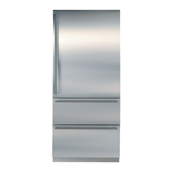
- Page 5 INTEGRA SERIES INTEGRA SERIES General Information (736 T (736 T all SWS #2970000) all SWS #2970000) MODEL DESCRIPTION Freezer 36 Series, ” Wide , w/ cemaker 736TFI All one Freezer Zone Figure 1-4. Model 736TFI #7015817 - Revision A - January, 2010...
- Page 6 INTEGRA SERIES INTEGRA SERIES General Information (736 T (736 T all SWS #2970000) all SWS #2970000) INSTALLATION CONSIDERATIONS This section covers some of the more common installation issues seen by a service technician. An improper instal- lation, though not a valid service issue, has the potential to lead to a customer placing a call for service. Installation related customer complaints could include, but are not limited to: Unit leveling, unit movement, door misalignment, doors and drawers not sealing, internal frost or condensation, warm compartment temperatures, exterior condensa- tion, etc..
- Page 7 INTEGRA SERIES INTEGRA SERIES General Information (736 T (736 T all SWS #2970000) all SWS #2970000) The rear levelers are adjusted from the front of the base by turning the Phillips head adjusting screw. The long adjusting screw reaches all the way to the rear lev- eler assembly.
- Page 8 INTEGRA SERIES INTEGRA SERIES General Information (736 T (736 T all SWS #2970000) all SWS #2970000) Dual Unit Installations If two or more units are placed side by side and are 2” or less apart, a dual unit heater package must be applied to the left side of the right hand unit.
- Page 9 INTEGRA SERIES INTEGRA SERIES General Information (736 T (736 T all SWS #2970000) all SWS #2970000) ELECTRONIC CONTROL TERMINOLOGY & COMPONENT DESCRIPTIONS The appliances described in this manual utilize an electronic control system which monitors, regulates, controls and displays a variety of functions and operations in the appliance. The table below defines some of the basic electronic control system terminology.
- Page 10 INTEGRA SERIES INTEGRA SERIES General Information (736 T (736 T all SWS #2970000) all SWS #2970000) BASIC ELECTRONIC CONTROL SYSTEM Input operations for the electronic control system are performed at the control panel membrane switch, with monitor- ing, regulating and controlling taking place at the control board . Temperatures and possible problems with the unit are displayed in the LCD at the control panel assembly.
- Page 11 INTEGRA SERIES INTEGRA SERIES General Information (736 T (736 T all SWS #2970000) all SWS #2970000) CONTROL BOARD LAYOUT AND SUMMARY TABLE The electrical connection points on the control board are labeled alphanumerically. These labels correspond with the alphanumeric control board summary table, located on the wiring diagrams. By referencing the summary table, it is possible to identify which components are connected at which connection points on the control board.
- Page 12 INTEGRA SERIES INTEGRA SERIES General Information (736 T (736 T all SWS #2970000) all SWS #2970000) CONTROL PANEL LAYOUT Please note that an illustration of the 736TCI control panel is used in most cases for this section. (See Fig. 3-4) REFRIGERATOR ICEMAKER SYSTEM UNIT...
- Page 13 INTEGRA SERIES INTEGRA SERIES General Information (736 T (736 T all SWS #2970000) all SWS #2970000) Adjusting Set-Point (Temperature Adjustment) To adjust set-points, press WARMER or COLDER key on control panel in multiple key strokes until desired set-point is achieved (See Figure 3-6).
- Page 14 INTEGRA SERIES INTEGRA SERIES General Information (736 T (736 T all SWS #2970000) all SWS #2970000) UNIQUE ELECTRONIC CONTROL INPUT OPERATIONS The following pages illustrate unique input operations performed at the control panel that you would not expect a customer to perform every day. The input operations described are: Temperature Unit Selection Mode, Sabbath Mode, Showroom Mode, Manual Zone Disable Mode and Manual Freezer Evaporator Defrost.
- Page 15 INTEGRA SERIES INTEGRA SERIES General Information (736 T (736 T all SWS #2970000) all SWS #2970000) Sabbath Mode Sabbath Mode was incorporated into the electronic control system for the observance of certain religious days. Initiating Sabbath Mode disables the LCD, lighting system, ice making system and door ajar alarm feature. To initiate Sabbath Mode, the unit must first be switched OFF using the UNIT ON/OFF key (See Figure 3-11), then...
- Page 16 INTEGRA SERIES INTEGRA SERIES General Information (736 T (736 T all SWS #2970000) all SWS #2970000) Manual Zone Disable Mode Manual Zone Disable Mode allows a customer or Service Technician to switch one zone off for interior cleaning, defrosting, or diagnostic purposes, while allowing the other zone to continue cooling. To initiate Manual Zone Disable Mode, the unit must first be switched OFF using the UNIT ON/OFF key (See Figure 3-15), then press and hold the WARMER key for the zone being disabled, then the UNIT ON/OFF key, then release...
- Page 17 INTEGRA SERIES INTEGRA SERIES General Information (736 T (736 T all SWS #2970000) all SWS #2970000) FUNCTIONS OF THE ELECTRONIC CONTROL SYSTEM The following pages explain monitoring, regulating and controlling functions of the electronic control system. In most cases signal traces of a model 736TCI wiring schematic are used to show current flow for functions being explained. Supply Power to the Lighting System AC line voltage is supplied to the lighting system through the control board when the unit is switched ON by pressing the UNIT ON/OFF key, so when the door or drawers are open, the light switches allows power to the lights...
- Page 18 INTEGRA SERIES INTEGRA SERIES General Information (736 T (736 T all SWS #2970000) all SWS #2970000) Monitor, Regulate and Display Compartment Temperatures The temperature signal from the compartment thermistors is monitored by the microprocessor and the average tem- perature is displayed, though the actual air temperature may fluctuate slightly (See Figure 3-19).
- Page 19 INTEGRA SERIES INTEGRA SERIES General Information (736 T (736 T all SWS #2970000) all SWS #2970000) Control Condenser Fan Run In all models except the 736TFI, the microprocessor senses the line volt output supplied to both compressors. If either compressor is running, a signal is sent to the condenser fan relay on the control board to close, supplying power to the condenser fan.
- Page 20 INTEGRA SERIES INTEGRA SERIES General Information (736 T (736 T all SWS #2970000) all SWS #2970000) Monitor and Control Refrigerator “Fan-Assisted, Off-Cycle Defrost” Temperature signals from refrigerator evaporator's thermistors are observed by the microprocessor. During off cycle defrost, if a refrigerator zone temperature reaches high offset (calling for cooling) before evaporator temperature rises to 38°F (3°C), no power will be supplied the the compressor.
- Page 21 INTEGRA SERIES INTEGRA SERIES General Information (736 T (736 T all SWS #2970000) all SWS #2970000) Monitor and Control Freezer “Adaptive Defrost” Initially the freezer compressor will cycle-run for twelve hours (twenty-four hours in the model 736TFI), after which the microprocessor sends the signal to the defrost relay on the control board to close. This supplies power to the defrost heater, and the compressor is switched off (See Figure 3-22).
- Page 22 INTEGRA SERIES INTEGRA SERIES General Information (736 T (736 T all SWS #2970000) all SWS #2970000) Monitor Compressor Run Duration, Displays If Service is Needed The microprocessor observes the changing state of the compressor relays to determine the length of compressor run time (See Figure 3-23).
- Page 23 INTEGRA SERIES INTEGRA SERIES General Information (736 T (736 T all SWS #2970000) all SWS #2970000) Monitor Icemaker System and Display If Service is Needed The drawer lighting signal is observed via the orange/black wire, used to indicate whether a drawer switch is open or closed;...
- Page 24 INTEGRA SERIES INTEGRA SERIES General Information (736 T (736 T all SWS #2970000) all SWS #2970000) POSSIBLE ERROR INDICATORS These pages contain diagrams illustrating what a customer may see on the LCD if there is a problem with the unit. NOTE: To clear indicators and error codes, problem must be corrected then press Bell ON/OFF key for 15 seconds.
- Page 25 INTEGRA SERIES INTEGRA SERIES General Information (736 T (736 T all SWS #2970000) all SWS #2970000) SERVICE UNIT FREEZER REFRIGERATOR COLDER WARMER COLDER WARMER ON/OFF ON/OFF ON/OFF Figure 3-33. 736TR “EE” at Left and “SERVICE” Flashing = Lower Compartment Thermistor (or its Wiring) Fault SERVICE UNIT FREEZER...
- Page 26 INTEGRA SERIES INTEGRA SERIES General Information (736 T (736 T all SWS #2970000) all SWS #2970000) SERVICE UNIT FREEZER COLDER WARMER ON/OFF ON/OFF ON/OFF Figure 3-39. 736TFI “EE” at Left and “SERVICE” Flashing = Freezer Compartment Thermistor (or its Wiring) Fault SERVICE UNIT FREEZER...
- Page 27 INTEGRA SERIES INTEGRA SERIES General Information (736 T (736 T all SWS #2970000) all SWS #2970000) TROUBLESHOOTING INPUT OPERATIONS The following few pages explain troubleshooting input operations performed at the control panel. The input opera- tions described are Diagnostic Mode, Manual Component Activation Mode and Temperature Log Recall. Diagnostic Mode Initiating Diagnostic Mode allows the Service Technician to observe real-time temperature readings from all thermis- tors without temperature averaging.
- Page 28 INTEGRA SERIES INTEGRA SERIES General Information (736 T (736 T all SWS #2970000) all SWS #2970000) 736TCI 736TR 736TFI THERMISTOR LOCATION CODE THERMISTOR LOCATION CODE THERMISTOR LOCATION CODE Freezer Compartment Lower Compartment Freezer Compartment Refrigerator Compartment Upper Compartment Freezer Evaporator Freezer Evaporator Lower Evaporator Refrigerator Evaporator...
- Page 29 INTEGRA SERIES INTEGRA SERIES General Information (736 T (736 T all SWS #2970000) all SWS #2970000) Error Code Table CODE INDICATION Refrig. cabinet thermistor read open or shorted for 10+ seconds, or repeatedly read erratic temp’s Refrig. evaporator thermistor read open or shorted for 10+ seconds, or repeatedly read erratic temp’s Freezer cabinet thermistor read open or shorted for 10+ seconds, or repeatedly read erratic temp’s Freezer evaporator thermistor read open or shorted for 10+ seconds, or repeatedly read erratic temp’s Defrost under-heat with no voltage feedback through Gray/White wire at defrost start...
- Page 30 INTEGRA SERIES INTEGRA SERIES General Information (736 T (736 T all SWS #2970000) all SWS #2970000) Manual Component Activation Mode Manual Component Activation Mode allows a Service Technician to energize a cooling system for five minutes. When activated, the chosen zone’s compressor and evaporator fan are energized along with the condenser fan. While in Component Activation Mode, the evaporator temperatures for that zone are displayed on the LCD.
- Page 31 INTEGRA SERIES INTEGRA SERIES General Information (736 T (736 T all SWS #2970000) all SWS #2970000) Temperature Log Recall Mode The electronic control system is equipped with a temperature history data storage system. This system logs/stores the average temperature of each individual thermistor every two hours, along with any event indicators (explained later in this section), that may have occurred.
- Page 32 INTEGRA SERIES INTEGRA SERIES General Information (736 T (736 T all SWS #2970000) all SWS #2970000) Initiate Temperature Log Recall Mode To View Compartment and Evaporator Temperature History - Begin with the unit ON and in Diagnostic Mode (See Figure 3-57). While in Diagnostic Mode, toggle through the readings until the desired thermistor temperature is displayed on the LCD (See Figure 3-58).
- Page 33 INTEGRA SERIES INTEGRA SERIES General Information (736 T (736 T all SWS #2970000) all SWS #2970000) Possible Temperature Log Recall Mode Event Indicators The diagrams below illustrate possible event indicators that may be observed while in Temperature Log Recall Mode. (See Figures 3-62 through 3-65) UNIT FREEZER...
- Page 34 INTEGRA SERIES INTEGRA SERIES General Information (736 T (736 T all SWS #2970000) all SWS #2970000) Temperature Log Index Chart NOTE : The chart below applies to the hours in which the control has power. Temperature history data will only be stored when the control has AC line voltage supplied to it.
- Page 35 INTEGRA SERIES INTEGRA SERIES Sealed System Information (736 T all SWS #2970000) (736 T all SWS #2970000) HFC-134a REFRIGERANT SERVICE INFORMATION The sealed system in this Series contain HFC-134a refrigerant. This section of the manual provides general rules for working with 134a, and procedures to be followed while servicing the sealed system. This is followed by dia- grams illustrating sealed system operation, then model-specific refrigerant flow diagrams.
- Page 36 INTEGRA SERIES INTEGRA SERIES (736 T all SWS #2970000) Sealed System Information (736 T all SWS #2970000) BUILT-IN SERIES SEALED SYSTEM REPAIR PROCEDURES Problem Service Procedures Non-Operating, Inefficient, Capture refrigerant Noisy Compressor Replace Compressor Replace filter-drier Evacuate or sweep charge system Recharge system with Virgin 134a refrigerant.
- Page 37 INTEGRA SERIES INTEGRA SERIES Sealed System Information (736 T all SWS #2970000) (736 T all SWS #2970000) SEALED SYSTEM OPERATION The six diagrams on these pages illustrate a basic sealed system. The components are listed in order of refrigerant flow, with an explanation of their fundamental role as part of a sealed system.
- Page 38 INTEGRA SERIES INTEGRA SERIES (736 T all SWS #2970000) Sealed System Information (736 T all SWS #2970000) Capillary Tube (& Heat Exchanger) (Figure 4-4) The warm liquid refrigerant travels through the long skinny capillary tube which is soldered to the suction line. (These two tubes soldered together create the heat exchanger.) As the warm liquid refrigerant travels through the capillary tube it gives up heat to the cool refrigerant gas traveling...
- Page 39 INTEGRA SERIES INTEGRA SERIES Sealed System Information (736 T all SWS #2970000) (736 T all SWS #2970000) SEALED SYSTEM REFRIGERANT FLOW DIAGRAMS = REFRIGERATOR SEALED SYSTEM = FREEZER SEALED SYSTEM FRAME HEATER (HOT GAS) REFRIGERATOR EVAPORATOR REFRIGERATOR HEAT-EXCHANGER FREEZER HEAT-EXCHANGER FREEZER EVAPORATOR FREEZER FILTER-DRIER REFRIGERATOR COMPRESSOR...
- Page 40 INTEGRA SERIES INTEGRA SERIES (736 T all SWS #2970000) Sealed System Information (736 T all SWS #2970000) = UPPER REFRIGERATOR SEALED SYSTEM = LOWER REFRIGERATOR SEALED SYSTEM FRAME HEATER (HOT GAS) REFRIGERATOR EVAPORATOR (UPPER) REFRIGERATOR HEAT-EXCHANGER (UPPER) REFRIGRATOR HEAT-EXCHANGER REFRIGERATOR EVAPORATOR (LOWER) (LOWER) REFRIGERATOR FILTER-DRIER (UPR)
- Page 41 INTEGRA SERIES INTEGRA SERIES Airflow Information (736 T (736 T all SWS #2970000) all SWS #2970000) AIRFLOW DIAGRAMS UPPER FAN MOTOR For proper airflow, evaporator fan LOWER FAN MOTOR blades must be pushed onto the fan motor shafts fully, so that the motor shafts touch the fan blade stop point.
- Page 42 INTEGRA SERIES INTEGRA SERIES Airflow Information (736 T (736 T all SWS #2970000) all SWS #2970000) UPPER FAN MOTOR For proper airflow, evaporator fan blades must be pushed onto the fan motor shafts LOWER FAN MOTOR fully, so that the motor shafts touch the fan blade stop point.
- Page 43 INTEGRA SERIES INTEGRA SERIES General Information (736 T (736 T all SWS #2970000) all SWS #2970000) ICEMAKER SYSTEM INFORMATION Timing Cam - The timing cam is attached to the tim- ing gear and the ice ejector is inserted into the center of This Series units utilizes a Nidec-Servo ®...
- Page 44 INTEGRA SERIES INTEGRA SERIES General Information (736 T (736 T all SWS #2970000) all SWS #2970000) FILL CUP EJECTOR HARNESS MOLD BODY THERMOSTAT SUPPORT ICE STRIPPER BRACKET HOLD SW MOTOR SHUT-OFF ARM LEVER BAIL ARM (LONG) COVER WATER SW GEAR MOUNTING PLATE Figure 6-1.
- Page 45 INTEGRA SERIES INTEGRA SERIES General Information (736 T (736 T all SWS #2970000) all SWS #2970000) 115 VOLTS 60 CYCLES THERMOSTAT SHUT-OFF SWITCH MOLD HEATER Start of the First Revolution (See Figure 6-3) • The water in the ice mold has turned to ice. SOLENOID SWITCH •...
- Page 46 INTEGRA SERIES INTEGRA SERIES General Information (736 T (736 T all SWS #2970000) all SWS #2970000) 115 VOLTS 60 CYCLES THERMOSTAT SHUT-OFF SWITCH MOLD HEATER First Revolution Continued (See Figure 6-5) • The ice ejector reach the ice in the mold. SOLENOID SWITCH •...
- Page 47 INTEGRA SERIES INTEGRA SERIES General Information (736 T (736 T all SWS #2970000) all SWS #2970000) 115 VOLTS 60 CYCLES THERMOSTAT SHUT-OFF SWITCH MOLD HEATER End of First Revolution (See Figure 6-7) SOLENOID SWITCH • The water valve solenoid switch is tripped by the MOTOR timing cam back to “normally open.”...
- Page 48 INTEGRA SERIES INTEGRA SERIES General Information (736 T (736 T all SWS #2970000) all SWS #2970000) 115 VOLTS 60 CYCLES THERMOSTAT SHUT-OFF SWITCH MOLD HEATER Second Revolution Continued (See Figure 6-9) SOLENOID SWITCH • The mold heater has warmed the thermostat, so the thermostat opens, and the mold heater is de-ener- MOTOR gized.
- Page 49 INTEGRA SERIES INTEGRA SERIES General Information (736 T (736 T all SWS #2970000) all SWS #2970000) 115 VOLTS 60 CYCLES End of Ice making Cycle (See Figure 6-11) THERMOSTAT SHUT-OFF SWITCH • The water valve solenoid switch is tripped by the MOLD HEATER timing cam back to “normally open”...
- Page 50 INTEGRA SERIES INTEGRA SERIES General Information (736 T (736 T all SWS #2970000) all SWS #2970000) MANUALLY STARTING THE ICEMAKER NOTE: To allow ice to freeze fully and reduce effects of low water pressure, the electronic control disables the icemaker system for forty-five (45) minutes after each Turn Drive Gear ice harvest.
- Page 51 INTEGRA SERIES INTEGRA SERIES General Information (736 T (736 T all SWS #2970000) all SWS #2970000) ICEMAKER FAULT TESTING ICEMAKER TROUBLESHOOTING No / Slow Ice Production Bypass 45-minute dwell by pressing ICE ON/OFF key to OFF, 1 Ice maker system switched OFF. Switch system ON. then again to ON.
- Page 52 INTEGRA SERIES INTEGRA SERIES Component Removal (736 T (736 T all SWS #2970000) all SWS #2970000) COMPONENT REMOVAL This section explains how to remove components from 736 Series Units starting with serial # 2970000. If different models have similar adjusting, accessing and/or removal procedures, they are grouped together under the appropriate heading.
- Page 53 INTEGRA SERIES INTEGRA SERIES Component Removal (736 T (736 T all SWS #2970000) all SWS #2970000) EXTERIOR COSMETIC AND MECHANICAL COMPONENTS Kickplate/Grille Removal (All Models) The kickplate/grille is attached by four screws passing through the kickplate into adjustable kickplate brackets. NOTE: Because drawer panels may extend down in front of the kickplate/grille, it may be necessary to...
- Page 54 INTEGRA SERIES INTEGRA SERIES Component Removal (736 T (736 T all SWS #2970000) all SWS #2970000) Drawer Assembly Removal (All Models) There are inverted channels on both sides of the draw- er tubs which rest on telescoping drawer slide assem- Hole in Channel blies.
- Page 55 INTEGRA SERIES INTEGRA SERIES Component Removal (736 T (736 T all SWS #2970000) all SWS #2970000) Door Assembly Removal (All Models) Remove two inner-most screws at top and bottom The door assembly is held in place with Allen-head hinge with door open. Remove two outer-most screws that pass down through the arm of the top hinge screws at bottom hinge...
- Page 56 INTEGRA SERIES INTEGRA SERIES Component Removal (736 T (736 T all SWS #2970000) all SWS #2970000) INTERIOR COSMETIC, MECHANICAL AND ELEC- TRICAL COMPONENTS Door Shelf Door Shelf and Dairy Compartment Adjustment / Removal (All Models) There are “L” shaped grooves in the end caps of the “L”...
- Page 57 INTEGRA SERIES INTEGRA SERIES Component Removal (736 T (736 T all SWS #2970000) all SWS #2970000) Upper Light Diffuser Removal (All Models) “T” Slots The side frames of the upper light diffuser have four inverted “T” shaped slots (two each side) which fit over pegs protruding from the side walls of the upper com- partment.
- Page 58 INTEGRA SERIES INTEGRA SERIES Component Removal (736 T (736 T all SWS #2970000) all SWS #2970000) Control Board Removal (All Models) The control board is held in position by two sets of tabs behind the left side of the control panel. The two for- ward tabs position the LCD in the control panel window, Control Panel while the other two tabs secure the middle of the control...
- Page 59 INTEGRA SERIES INTEGRA SERIES Component Removal (736 T (736 T all SWS #2970000) all SWS #2970000) Upper Evaporator Cover / Air Duct Removal (All Models) The bottom of the upper evaporator cover sets into a channel at the bottom of the upper compartment. At the top, screws hold the evaporator cover to the evapo- rator fan shroud.
- Page 60 INTEGRA SERIES INTEGRA SERIES Component Removal (736 T (736 T all SWS #2970000) all SWS #2970000) Upper Compartment Evaporator Fan Assembly Removal (All Models) The upper evaporator fan assembly sets in a pocket in the ceiling of the upper compartment and is secured to the ceiling with screws.
- Page 61 INTEGRA SERIES INTEGRA SERIES Component Removal (736 T (736 T all SWS #2970000) all SWS #2970000) Drawer Closer Assembly Removal (All Models) Drawer Closer Assy The drawer closer assemblies are located on the right and left side walls, towards the front of the two drawer areas.
- Page 62 INTEGRA SERIES INTEGRA SERIES Component Removal (736 T (736 T all SWS #2970000) all SWS #2970000) Icemaker Assembly Removal Shut-off Arm (736TFI, 736TCI) The icemaker sits on a support plate with screws pass- Connecting Rod ing up through the plate into the icemaker bottom. P- clamps fitting around the back rod of the ice level arm and screws secured the ice level arm to the plate.
- Page 63 INTEGRA SERIES INTEGRA SERIES Component Removal (736 T (736 T all SWS #2970000) all SWS #2970000) Lower Evaporator Fan Assembly Removal (Models 736TR) Evap Fan Assy The lower evaporator fan assembly is held in place by bolts passing through access holes in the evaporator fan shroud, then through the top flange of the evapora- tor cover and into well-nuts in the fan bracket.
- Page 64 INTEGRA SERIES INTEGRA SERIES Component Removal (736 T (736 T all SWS #2970000) all SWS #2970000) Lower Evaporator Cover Removal (Model 736TFI) The lower evaporator cover is held in place with screws. At the left side the screws are hidden by the heat-exchanger cover;...
- Page 65 INTEGRA SERIES INTEGRA SERIES Component Removal (736 T (736 T all SWS #2970000) all SWS #2970000) Lower Evaporator Fan Assembly Removal Evaporator Fan Assembly (736TCI) Electrical Connections The evaporator fan assembly is attached to the upper back wall of the lower compartment with screws. To remove the fan assembly, first remove drawers, left side drawer slides, heat exchanger cover, evaporator cover and the fan shroud, then...
- Page 66 INTEGRA SERIES INTEGRA SERIES Component Removal (736 T (736 T all SWS #2970000) all SWS #2970000) Lower Thermistor Removals (736TCI) Compartment Thermistor A screw and P-clamp is used to secure the compart- ment thermistor to the rear wall, slightly above and to the right of the evaporator.
- Page 67 INTEGRA SERIES INTEGRA SERIES Component Removal (736 T (736 T all SWS #2970000) all SWS #2970000) COMPRESSOR AREA ELECTRICAL AND MECHANI- CAL COMPONENTS Screw Icemaker Water Valve Removal (736TFI & 736TCI) The icemaker water valve assembly is located at the right side of the compressor area next to the condenser, and is attached to the valve bracket with screws.
- Page 68 INTEGRA SERIES INTEGRA SERIES Component Removal (736 T (736 T all SWS #2970000) all SWS #2970000) Condenser Fan Assembly Removal Screw The condenser fan shroud sets on top of two pegs pro- truding from the unit tray and two screws at the top of the shroud secure it to the condenser.
- Page 69 INTEGRA SERIES INTEGRA SERIES Component Removal (736 T (736 T all SWS #2970000) all SWS #2970000) SEALED SYSTEM COMPONENTS Upper Refrigerator Compartment Evaporator Removal (736TR, 736TCI) 1" The upper evaporator is attached to the back wall with screws. NOTE: Before attempting to remove the evaporator, 2"...
- Page 70 INTEGRA SERIES INTEGRA SERIES Component Removal (736 T (736 T all SWS #2970000) all SWS #2970000) High-Side Filter-Drier Removal Screw The high-side filter-driers are located in the center of the unit tray, behind the condenser and are attached to the drier bracket with a cable tie. NOTE: Before attempting to remove a filter drier, evac- uate the refrigerant from the sealed system.
- Page 71 INTEGRA SERIES INTEGRA SERIES Component Removal (736 T (736 T all SWS #2970000) all SWS #2970000) Compressor Removal The compressors have four rubber compressor grom- mets inserted into their base. Cylindrical metal spacers are placed over threaded studs that are pressed into the unit tray.
- Page 72 INTEGRA SERIES INTEGRA SERIES Component Removal (736 T (736 T all SWS #2970000) all SWS #2970000) Condenser Removal Screw The condenser is secured to the unit tray by four rivets that pass up through the unit tray into the condenser side brackets.
- Page 73 INTEGRA SERIES INTEGRA SERIES Component Removal (736 T (736 T all SWS #2970000) all SWS #2970000) Upper Compartment Heat Exchanger Removal 1" The upper compartment heat exchanger passes down through a hole in the back left corner of the mullion. The heat exchanger then passes down through the 2"...
- Page 74 INTEGRA SERIES INTEGRA SERIES Component Removal (736 T (736 T all SWS #2970000) all SWS #2970000) Lower Compartment Heat Exchanger Removal The lower compartment heat exchanger is behind the switch enclosure and passes down through a hole in the back right corner of the lower compartment floor. Cut here NOTE: Before attempting to remove a heat exchanger,...
- Page 75 INTEGRA SERIES INTEGRA SERIES Troubleshooting (736 T (736 T all SWS #2970000) all SWS #2970000) TROUBLESHOOTING GUIDES This section of the manual contains: • The Error Code Table and Error Code Troubleshooting Guide. • The General Troubleshooting Guide, which covers all problems that a 736 Series, starting with Serial #2970000, may experience.
- Page 76 INTEGRA SERIES INTEGRA SERIES Troubleshooting (736 T (736 T all SWS #2970000) all SWS #2970000) ERROR CODE TROUBLESHOOTING GUIDE ERROR CODE TEST / ACTION Check refrigerator compartment thermistor electrical connections and continuity from thermistor to J1 on control board. Reconnect / repair connections. Check resistance of refrigerator compartment thermistor for 30,000 to 33,000 ohms at 32°F (0°C).
- Page 77 INTEGRA SERIES INTEGRA SERIES Troubleshooting (736 T (736 T all SWS #2970000) all SWS #2970000) ERROR CODE TROUBLESHOOTING GUIDE ERROR CODE TEST / ACTION A. Check for jammed cube in icemaker. B. Reference wiring diagram to identify components in same White wire circuit as water valve solenoid. Check all White wire electrical connections and continuity from water valve solenoid to J7-8 on control board.
- Page 78 INTEGRA SERIES INTEGRA SERIES Troubleshooting (736 T (736 T all SWS #2970000) all SWS #2970000) HOW TO USE GENERAL TROUBLESHOOTING GUIDE The General Troubleshooting Guide Table of Contents on the following page indicates how the General Trouble Shooting Guide is arranged. Match the description of the problem the unit is experiencing with those in the table. To the left of the problem description is a letter.
-
Page 79: Table Of Contents
INTEGRA SERIES INTEGRA SERIES Troubleshooting (736 T (736 T all SWS #2970000) all SWS #2970000) GENERAL TROUBLESHOOTING GUIDE TABLE OF CONTENTS Ltr Problem Description Page # Error Codes and “SERVICE” Flashing ..........................8-7 “EE” Displayed in Place of Freezer Temperature with “SERVICE” Flashing ............... 8-7 C. -
Page 80: Error Codes And "Service" Flashing
INTEGRA SERIES INTEGRA SERIES Troubleshooting (736 T (736 T all SWS #2970000) all SWS #2970000) PROBLEM POSSIBLE CAUSE TEST / ACTION A. Error Codes & “SERVICE” Unit Experienced Temperature Problems See Error Code Troubleshooting Guide Flashing B. “EE” Displayed in Place of Freezer Compartment Thermistor Check wiring from thermistor to control Freezer Temperature with... - Page 81 INTEGRA SERIES INTEGRA SERIES Troubleshooting (736 T (736 T all SWS #2970000) all SWS #2970000) PROBLEM POSSIBLE CAUSE TEST / ACTION (Continued) Light ON with Door/ Drawers Closed G. Warm Freezer Temperature a. Top hinge cover missing, not depress- a. Replace hinge cover. with “SERVICE”...
- Page 82 INTEGRA SERIES INTEGRA SERIES Troubleshooting (736 T (736 T all SWS #2970000) all SWS #2970000) PROBLEM POSSIBLE CAUSE TEST / ACTION H. Warm Freezer Temperatures No Power to Unit Check power to unit, plug unit in or switch without “SERVICE” Flashing supply circuit breaker ON.
- Page 83 INTEGRA SERIES INTEGRA SERIES Troubleshooting (736 T (736 T all SWS #2970000) all SWS #2970000) PROBLEM POSSIBLE CAUSE TEST / ACTION (Continued) Evaporator Fan Fault H. Warm Freezer Temperatures a. Top hinge cover missing, not depress- a. Replace hinge cover. without “SERVICE”...
- Page 84 INTEGRA SERIES INTEGRA SERIES Troubleshooting (736 T (736 T all SWS #2970000) all SWS #2970000) PROBLEM POSSIBLE CAUSE TEST / ACTION I. Warm Refrigerator Door or Drawer Ajar Temperatures with “SERVICE” Flashing a. Food product obstruction a. Move obstruction. b. Door/cabinet hinge problem b.
- Page 85 INTEGRA SERIES INTEGRA SERIES Troubleshooting (736 T (736 T all SWS #2970000) all SWS #2970000) PROBLEM POSSIBLE CAUSE TEST / ACTION (Continued) Evaporator Heavily Frosted I. Warm Refrigerator a. Door or drawer ajar a. See Door or Drawer Ajar above. Temperatures with b.
- Page 86 INTEGRA SERIES INTEGRA SERIES Troubleshooting (736 T (736 T all SWS #2970000) all SWS #2970000) PROBLEM POSSIBLE CAUSE TEST / ACTION (Continued) Lights ON with Door/ Drawers Closed J. Warm Refrigerator a. Top hinge cover missing, not depress- a. Replace hinge cover. Temperatures without ing light switch “SERVICE”...
- Page 87 INTEGRA SERIES INTEGRA SERIES Troubleshooting (736 T (736 T all SWS #2970000) all SWS #2970000) PROBLEM POSSIBLE CAUSE TEST / ACTION K. Warm or Normal High Room Ambient Instruct customer unit performs best Temperatures in Both between 60°F(16°C) and 90°F(32°C). Compartments with “SERVICE”...
- Page 88 INTEGRA SERIES INTEGRA SERIES Troubleshooting (736 T (736 T all SWS #2970000) all SWS #2970000) PROBLEM POSSIBLE CAUSE TEST / ACTION (Continued) Condenser Air Flow L. Warm Temperatures in Both Compartments without a. Dirty condenser a. Clean condenser. “SERVICE” Flashing b.
-
Page 89: No Ice, "Ice" Displayed On Lcd, But Not Flashing
INTEGRA SERIES INTEGRA SERIES Troubleshooting (736 T (736 T all SWS #2970000) all SWS #2970000) PROBLEM POSSIBLE CAUSE TEST / ACTION P. No Ice, "ICE" Displayed on Unit Has Not Run Long Enough Freezer must be 17°F for icemaker to oper- LCD, but not Flashing ate, approximately 24 hours after unit instal- lation. -
Page 90: Icemaker Produces Hollow Cubes
INTEGRA SERIES INTEGRA SERIES Troubleshooting (736 T (736 T all SWS #2970000) all SWS #2970000) PROBLEM POSSIBLE CAUSE TEST / ACTION Q. No Ice and "ICE" Not Icemaker System Not Energized Press ICE key. “ ICE” should appear on Displayed on LCD LCD. -
Page 91: Membrane Switch On Control Board Malfunctioning
INTEGRA SERIES INTEGRA SERIES Troubleshooting (736 T (736 T all SWS #2970000) all SWS #2970000) PROBLEM POSSIBLE CAUSE TEST / ACTION V. Membrane Switch on Control Control Panel Ribbon Cable Check control panel ribbon cable. All Pins Board Malfunctioning Disconnected or Connected Incorrectly on board should be in ribbon cable terminal housing. -
Page 92: Door Or Drawers Not Able To Close Completely
INTEGRA SERIES INTEGRA SERIES Troubleshooting (736 T (736 T all SWS #2970000) all SWS #2970000) PROBLEM POSSIBLE CAUSE TEST / ACTION X. Lights Stay ON when Door Door or Drawer Ajar &/or Drawers are Closed - (May be Accompanied by a. -
Page 93: Sealed System Troubleshooting /Diagnostic Tables
INTEGRA SERIES INTEGRA SERIES Troubleshooting (736 T (736 T all SWS #2970000) all SWS #2970000) SEALED SYSTEM TROUBLESHOOTING / DIAGNOSTICS TABLES NORMAL OPERATING PRESSURES TABLE NOTES: • Only enter the sealed system to check pressures if the Error Code Troubleshooting Guide and General Troubleshooting Guide could not pinpoint the cause of the temperature problem. -
Page 94: Pressure Indications
INTEGRA SERIES INTEGRA SERIES Troubleshooting (736 T (736 T all SWS #2970000) all SWS #2970000) PRESSURE INDICATIONS If low-side pressure is & high-side pressure is possible problem is NORMAL NORMAL MECHANICAL (see General Troubleshooting Guide) LEAK HIGH RESTRICTION HIGH INEFFICIENT COMPRESSOR HIGH HIGH OVER CHARGE... -
Page 95: Control Panel Membrane Switch / Ribbon Cable Test
INTEGRA SERIES INTEGRA SERIES Troubleshooting (736 T (736 T all SWS #2970000) all SWS #2970000) CONTROL PANEL MEMBRANE SWITCH / RIBBON CABLE TEST If integrity of control panel assembly is suspect, perform continuity tests at membrane switch ribbon cable terminal housing. -
Page 96: Door Hinge Operation Test Procedures And Corrections
INTEGRA SERIES INTEGRA SERIES Troubleshooting (736 T (736 T all SWS #2970000) all SWS #2970000) TALL UNIT DOOR HINGE OPERATION TEST PROCEDURES AND CORRECTIONS 1. If the door of a 736 tall unit will not close properly, first check for obstructions. 2. - Page 97 INTEGRA SERIES INTEGRA SERIES Technical Data Information (736 T (736 T all SWS #2970000) all SWS #2970000) Model 736TCI REFRIGERATOR FREEZER CHARGE (R-134a Refrigerant) 5.25 oz. 8.5 oz. NOTE: Always check serial tag for exact charge NORMAL OPERATING PRESSURES Low Side 0-12 psi to 30-42 psi 5”-1 psi to 8-15 psi High Side...
- Page 98 INTEGRA SERIES INTEGRA SERIES Technical Data Information (736 T (736 T all SWS #2970000) all SWS #2970000) Model 736TR REFRIG. (Upper) REFRIG. (Lower) CHARGE (R-134a Refrigerant) 5.25 oz. 5.75 oz. NOTE: Always check serial tag for exact charge NORMAL OPERATING PRESSURES Low Side 0-12 psi to 30-42 psi 0-12 psi to 30-42 psi...
- Page 99 INTEGRA SERIES INTEGRA SERIES Technical Data Information (736 T (736 T all SWS #2970000) all SWS #2970000) Model 736TFI FREEZER CHARGE (R-134a Refrigerant) 8.25 oz. NOTE: Always check serial tag for exact charge NORMAL OPERATING PRESSURES Low Side (at Max Speed) 5”-1 psi to 8-15 psi High Side (at Max Speed) 75 psi to 120 psi...
- Page 100 INTEGRA SERIES INTEGRA SERIES Wiring Information (736 T (736 T all SWS #2970000) all SWS #2970000) P/N 7013369 WIRING DIAGRAM -This wiring information is provided for use by qualified MODEL: 736TCI service personnel only. -Disconnect appliance from electrical supply before beginning service.
- Page 101 INTEGRA SERIES INTEGRA SERIES Wiring Information (736 T (736 T all SWS #2970000) all SWS #2970000) P/N 7013369 WIRING SCHEMATIC -This wiring information is provided for use by qualified MODEL: 736TCI service personnel only. -Disconnect appliance from electrical supply before beginning service.
- Page 102 INTEGRA SERIES INTEGRA SERIES Wiring Information (736 T (736 T all SWS #2970000) all SWS #2970000) P/N 7013370 WIRING DIAGRAM -This wiring information is provided for use by qualified MODEL: 736R service personnel only. -Disconnect appliance from electrical supply before beginning service.
- Page 103 INTEGRA SERIES INTEGRA SERIES Wiring Information (736 T (736 T all SWS #2970000) all SWS #2970000) P/N 7013370 WIRING SCHEMATIC -This wiring information is provided for use by qualified MODEL: 736TR service personnel only. -Disconnect appliance from electrical supply before beginning service.
- Page 104 INTEGRA SERIES INTEGRA SERIES Wiring Information (736 T (736 T all SWS #2970000) all SWS #2970000) P/N 7010912 WIRING DIAGRAM -This wiring information is provided for use by qualified MODEL: 736TFI service personnel only. -Disconnect appliance from electrical supply before beginning service.
- Page 105 INTEGRA SERIES INTEGRA SERIES Wiring Information (736 T (736 T all SWS #2970000) all SWS #2970000) P/N 7010912 WIRING SCHEMATIC -This wiring information is provided for use by qualified MODEL: 736TFI service personnel only. -Disconnect appliance from electrical supply before beginning service.
Need help?
Do you have a question about the INTEGRATED Series and is the answer not in the manual?
Questions and answers