Advertisement
Quick Links
Advertisement

Related Manuals for KIRLOSKAR R1040 Series


Summary of Contents for KIRLOSKAR R1040 Series
- Page 1 OPERATION & MAINTENANCE MANUAL R1040 / R1080 / K1080 SERIES ENGINES...
- Page 3 We recommend that only trained manpower should Help Desk ID – koel.helpdesk@kirloskar.com perform the operation and maintenance tasks on the Visit us at: www.kirloskar.com engine. Always use the genuine Kirloskar spare parts www.koel.co.in Visit us at : www.koel.co.in whenever required for periodic maintenance as well...
- Page 5 STANDARD WARRANTY FOR KOEL R1040 / R1080 SERIES ENGINE OPERATING IN INDIA This warranty applies to the R1040 / R1080 Series KOEL Super Plus and avail the services from KOEL Authorised Diesel Engine for power generation application. Service dealer. Duration of Warranty Industrial Engines For Power Generation Non Cellular Application Within 18 Calendar Months from Date of Dispatch from...
- Page 6 At the termination of such period of 12 calendar months application or incorrect installation by the (or six calendar months as the case may be) all liability purchaser, or his employees or agents or in the on our part ceases. case of repairs or alterations carried out by the purchaser without our knowledge and written In the case of goods not of our manufacture (e.g.
- Page 7 Any damage resulting from improper shutdown. This warranty is the only document given by us Any failure to meet its obligations hereunder warranting the Kirloskar R1040 / R1080 series engine. which are due to circumstances beyond its No other document giving any warranty terms...
- Page 8 Observe all industrial safety regulations when engine are operating in enclosed spaces or underground. K - Cool Super Plus Coolant to avoid rust formation. Please contact your Kirloskar Dealer for Spare parts enquiry. Use only genuine spare parts. Service and Maintenance...
- Page 9 2. Engine Description 2.1 Engine numbering system 2.2 Engine illustrations 2.3 Engine lifting device 2.4 Lube oil system 2.5 Fuel system 2.6 Cooling system 2.7 Electrical system...
- Page 10 2. Engine Description...
- Page 11 RATING STD. RATED VOLTAGE GOVERNING CLASS RATED CURRENT ENGINE No. SERIAL NO. YEAR OF MANUFACTURE KIRLOSKAR OIL ENGINES LTD KIRLOSKAR OIL ENGINES LTD. INDIA INDIA Engine no is punched on the Name Plate which is fixed on the engine crankcase.
- Page 12 2.1 Engine numbering system 2. Engine Description 2.1.2 Engine number system 2.1.3 Model designation 3002 / 00001 1040 Indicates Piston displacement Engine serial No 1.04 Lit. / Cylinder as 1040 cc Year of Manufacturing Indicates series of engine as R series Application code No.
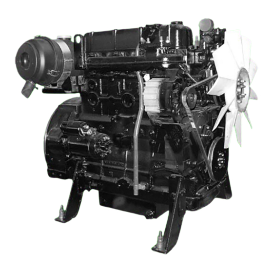
- Page 13 2.2 Engine illustration 2. Engine Description 2.2.1 Air inlet manifold side Air cleaner Aircleaner hose Adaptor plate F. W. E. Mtg. foot Crank case Dipstick G. E. Mtg. foot Spin-on lube oil filter Stopping lever Feed pump Gear casing Fuel pump Air inlet manifold H.
- Page 14 2.2 Engine illustration 2. Engine Description 2.2.2 Exhaust manifold side Thermostat / Thermostat Hsg. Radiator cooling fan Tension adjusting lever V - Belt Crankpulley Lube oil sump Breather tube Starter Flywheel housing Charging alternator Vacuator Valve Exhaust manifold Rocker cover Lube Oil filling point...
- Page 15 2.3 Engine lifting device 2. Engine Description 2.3.1 For bare engine – R1040 / R1080 Fig. above shows the recommended lifting device Before lifting the engine first fix the lifting hooks on the engine and then lift the engine. The lifting hooks provided on the engine are meant for lifting bare engine only.
- Page 16 2.4 Lube oil system 2. Engine Description 2.4.1 Lube oil circuit 2.4.2 Lube oil pump Force feed lubrication is provided by a ‘G’ rotor type pump to main Lube oil pump delivery bearings, large end bearings, camshaft journals, valve gear etc. Other components like connecting rod small end bushes, cylinder Engine type 2R/3R/4R1040/6R1080...
- Page 17 2.4 Lube oil system 2. Engine Description 2.4.3 Lubrication system for R1040 / R1080 Series engines A schematic diagram, shown below, shows the lubricating oil circuit of a typical R1040 / R1080 series engines Lube oil sump Suction tube Lube oil pump Pressure relief valve Delivery pipe Delivery body...
- Page 18 ‘full load’ even for a short duration; this is applicable for operating speed of 1500 rpm, under loaded condition, then stationary applications like power generation application. replace the lube oil filter cartridge and check the pressure. If the pressure is still low, then contact your Kirloskar Dealer.
- Page 19 2.4 Lube oil system 2. Engine Description 2.4.6 Lube oil sump capacity 2.4.7 Lube oil * Whenever Lube oil filter is drained off, add approximately The lube oil sump capacities of R1040 / R1080 series engines are as below 0.5 lit. / 1 lit. extra Lube oil (as per the size of the Spin-on filter cartridge) in the sump to maintain the correct oil level.) These capacities are for the standard sheet metal sumps.
- Page 20 2. Engine Description 2.4 Lube oil system 2.4.8 Quality Grade 2.4.9 Viscosity Lube oil of correct viscosity and detergency grades should be Multi-grade oil should be used. used It is recommended to use ‘K Oil Super’ (SAE15W40). For As the viscosity of lube oil is dependent on temperature. the detergency it should comply with following specifications:- choice of SAE grade should be governed by the ambient temperature prevailing at the engine operating site..
- Page 21 2.4 Lube oil system 2. Engine Description 2.4.9 Viscosity Only with preheating...
- Page 22 2.5 Fuel system 2. Engine Description 2.5.1 Fuel system * It the fuel tank is to be installed below the fuel pump level, and then the bottom level of the fuel tank should be less than 1 meter below the feed pump inlet * Fuel pipe from fuel tank to feed pump should be of 9mm I.D.
- Page 23 HIGH SPEED DIESEL dirt in fuel can cause wear on the injection equipment. Following points are important in use of fuel on Kirloskar R1040 / R1080 series engines. The following specifications are approved: - * IS:1460 - 2005 * ASTM D975-88:1-D &...
- Page 24 2.5 Fuel system 2. Engine Description 2.5.3 Storing Fuel Oil * The storage of fuel oil is of utmost importance since many engine problems are traced to dirty fuel or fuel stored for too long a period. Store fuel in a convenient place outside the building.
- Page 25 2.6 Cooling system 2. Engine Description 2.6.1 Radiator type cooling system 2.6.2 Coolant The engine uses a specially formulated coolant “K-Cool Super Plus” with deminteralised water & glycol. Use only “K-Cool Super Plus” coolant and do not use ordinary water. “K-Cool Super Plus” is available only through KOEL’s authorized dealer in suitable packings.
- Page 26 2.7 Electrical system 2. Engine Description 2.7.1 Electrical equipment 2.7.2 Battery & battery cables Super Plus coolant in the cooling system. Recommended Battery Capacity – 12V DC, 180 AH above 10 Standard engines are equipped with 12V, negative earth electrical 12V DC, 180 AH below 10 starting system.
-
Page 27: Table Of Contents
3. Engine Operation 3.1 Commissioning 3.2 Operating conditions 3.3 Starting & stopping 3.4 Running in period 3.5 Engine cleaning & preservation... - Page 28 3. Engine Operation...
-
Page 29: Commissioning
3. Engine Operation 3.1 Commissioning 3.1.1 Oil Before you start a new or overhauled engine, attend following points Oil filling Fill the engine with Lube oil through oil filling neck as shown in figure above. For oil quantity, grade and viscosity refer point no. - Page 30 3.1 Commissioning 3. Engine Operation 3.1.2 Cooling system 3.1.3 Belts Check that belts are in position and the belt tension is proper. If the belt tension is not proper adjust the same as described in section 5.4 * Fill the cooling system with recommended K-Cool Super Plus. Fill the coolant through neck of radiator till it flows through the radiator over flow pipe and then connect the pipe to balance water tank.
- Page 31 3.1 Commissioning 3. Engine Operation 3.1.4 Valve clearance 3.1.5 Other preparations * Check battery and lead connections. Also check the cable It is not necessary to check / adjust the valve clearance on a new connections at the starter & alternator. Loose connections lead engine as it is already adjusted at its required value in factory.
-
Page 32: Operating Conditions
3.2 Operating conditions 3. Engine Operation 3.2.1 Deration charts * The declared power ratings of the engine are obtained at The engine power mentioned on name plate is at NTP conditions. Based on altitude, ambient tempature & relative humidity engine standard reference conditions as per ISO 3046 / BS 5514 / DIN 6271 / IS 10000. - Page 33 3.2 Operating conditions 3. Engine Operation 3.2.1 Deration charts 3.2.1 Deration charts Deration chart for Turbocharged engines Deration chart for Turbocharged Aftercooled engines The deration chart applicable for R1040T/6R1080T engines is The deration chart applicable for 4R1040TA/6R1080TA engines illustrated below. is illustrated below...
-
Page 34: Starting & Stopping
3.3 Starting & stopping 3. Engine Operation 3.3.1 Lubrication - Precautions to be observed. * Fill recommended grade of fresh oil in the sump up to the high mark of the dipstick. * Add an additional 1/2 liter or 1 liter oil to compensate for the extra volume of the lube oil filter. - Page 35 3.3 Starting & stopping 3. Engine Operation 3.3.3 Cooling: Liquid cooled engines 3.3.4 Electrical * Fill the radiator with “K-Cool Super Plus” coolant only. * Check the battery for correct voltage and current capacity. * Check that the battery cables are correctly connected and * After starting the engine recheck the coolant level in the radiator and top up if required.
- Page 36 3.3 Starting & stopping 3. Engine Operation 3.3.5 Mechanical 3.3.6 Procedure of starting & stopping * Ensure that all electrical wiring of the alternator is intact. Before starting * Ensure that all the fasteners in the foundation, couplings etc * Check the oil and coolant levels - top up if required. are properly secured.
- Page 37 3.3 Starting & stopping 3. Engine Operation 3.3.6 Procedure of starting & stopping Stopping Before stopping * Unload the engine and let it run at idling speed for about 5 minutes. * Check if lube oil pressure and coolant temperature have stabilized.
-
Page 38: Running In Period
3.4 Running in period 3. Engine Operation 3.4.1 After first 50 hours running 3.4.2 After first 100 hours running * Change engine oil see 5.1.2 * Change the lube oil filter cartridge / element see 5.1.3 * Check and retighten fasteners for lube oil sump if necessary * Check V belt tension and retighten if necessary see 5.4 * Check engine for leakages of lube oil, fuel, water. -
Page 39: Engine Cleaning & Preservation
3.5 Engine cleaning & preservation 3. Engine Operation Remove the dust deposit from the engine and radiator fins with compressed air. Cleaning with diesel fuel or kerosene or water may cause dust to deposit again on the cleaned parts. * Cleaning should be done from the side opposite to the normal air flow. - Page 41 4. Routine Maintenance 4.1 Maintenance Schedule 4.2 Maintenance Work Completed...
- Page 42 4. Routine Maintenance...
- Page 43 4.1 Maintenance Schedule 4. Routine Maintenance Every In Running Hours 10th Refer Hour/ section Daily 1000 2500 5000 Engine oil level 5.1.1 Coolant level in radiator and compensatory tank 5.3.1 Restriction indicator of dry type air cleaner 5.4.2 — Rubber hose & clips of dry type air cleaner / radiator Engine oil ( Every 500 Hrs.) 5.1.2 Lube oil filter cartridge ( Every 500 Hrs.)
- Page 44 4.2 Maintenance Work Completed 4. Routine Maintenance Hours Date Remark Signature / Stamp 1000 1250 1500 1750 2000 2250 2500 2750 3000 3250 3500 3750 4000...
- Page 45 4.2 Maintenance Work Completed 4. Routine Maintenance Hours Date Remark Signature / Stamp 4250 4500 4750 5000 5250 5500 5750 6000 6250 6500 6750 7000 7250 7500 7750 8000...
- Page 46 4.2 Maintenance Work Completed 4. Routine Maintenance Hours Date Remark Signature / Stamp 8250 8500 8750 9000 Top Overhual and Major Overhaul periods The duration of the operating period before overhaul is dependant entirely on the quality of maintenance and service given to the engine and also type of environment and engine load cycle.
- Page 47 5. Service & Maintenance 5.1 Maintenance of lube system 5.2 Maintenance of fuel system 5.3 Maintenance of cooling system 5.4 Maintenance of dry type air cleaner 5.5 Belt drives 5.6 Adjustments 5.7 Maintenance of electrical equipment 5.8 Additional jobs...
- Page 48 5. Service & Maintenance...
- Page 49 5.1 Maintenance of lube system 5. Service & Maintenance 5.1.1 Checking oil level 5.1.2 Changing engine oil Removing engine oil * Stop the engine and wait for a while (Approximately 32 to 45 * Run engine until it gets warm. (lube oil temp. approx. 80°C) mins.) till oil level in the sump is settled.
- Page 50 5.1 Maintenance of lube system 5. Service & Maintenance 5.1.2 Changing engine oil 5.1.3 Changing lube oil filter Removing lub oil filter Removing engine oil Replace ‘Spin-on’ lube oil filter cartridge for every oil change. * Fill in fresh lube oil. * Release lube oil filter cartridge with special tool and spin off –...
- Page 51 5.1 Maintenance of lube system 5. Service & Maintenance 5.1.3 Changing lube oil filter Assembling lub oil filter * Clean sealing surface of filter carrier. * Tighten lube oil filter cartridge firmly by giving a final half turn as shown in figure above. * Fit the filter cartridge in dry condition.
- Page 52 5.2 Maintenance of fuel system 5. Service & Maintenance 5.2.1. Changing Fuel Filter - Spin On Type * Remove the cartridge by rotating in anticlockwise using * Clean the sealing surface of filter. commercial tool. * Apply light film of oil or diesel fuel to the rubber gasket of the * Collect driping fuel in a tray.
- Page 53 5.2 Maintenance of fuel system 5. Service & Maintenance 5.2.1. Changing Fuel Filter - Spin On Type 5.2.2. Changing Fuel Filter - Element Type * Tighten the fuel filter cartridge with a final half turn using * Close fuel valve commercial tool.
- Page 54 5.2 Maintenance of fuel system 5. Service & Maintenance 5.2.2. Changing Fuel Filter - Element Type 5.2.3. Fuel Strainer / Button Filter * Do not change Pre-filter insert & Micro filter insert at a time. * Discard the removed insert. * Change the sealing ring.
- Page 55 5.2 Maintenance of fuel system 5. Service & Maintenance 5.2.4 Lube Oil Filter & Fuel Filter With Common Filter Header Fuel Filter Lube Oil Filter * Lube oil filter & fuel filter (Spin On type) with common filter header can be supplied as an optional feature. * Adopt same procedure as mentioned in 5.2.1 for changing fuel filter - Spin on type and 5.1.3 for changing lube oil filter - Spin on type.
- Page 56 5.3 Maintenance of cooling 5. Service & Maintenance system 5.3.1 Radiator Engine cooling system consists of radiator, fan, water pump and temperature controller i e. thermostat. High coolant temperature trip for engine safety has been provided. Check coolant level in the balance water tank every day before starting the engine.
- Page 57 5.3 Maintenance of cooling 5. Service & Maintenance system 5.3.1 Radiator 5.3.2 How to clean the cooling systems with the help of K clean cleaner. * K Clean is designed to remove the contaminants like scale, oil, grease, rust, loose material present in the engine cooling systems.
- Page 58 5.3 Maintenance of Cooling 5. Service & Maintenance System 5.3.3 Thermostat Thermostat inspection A thermostat having single element is used in the cooling circuit. Thermostat is provided to attain working temperature quickly during warm-up period and maintains desired temperature of coolant during running of the engine.
- Page 59 5.4 Maintenance of dry type 5. Service & Maintenance air cleaner 5.4.1 Dry type air cleaner with plastic housing Dry type air cleaner with sheet metal housing Construction of typical dry type plastic air cleaner, supplied, is bottom of cover helps in expelling the accumulated dust. This is shown above in figure and construction of typical dry type air achieved by opening / closing of vacuator valve outlet due to the cleaner with sheet metal housing is shown above in figure.
- Page 60 5.4 Maintenance of dry type 5. Service & Maintenance air cleaner 5.4.2 Maintenance NOTES: - Regular check up and maintenance of the air cleaner is essential to ensure maximum protection to the engine from the dust. * If engine performance is poor, but restriction is still within limits, do not change the element.
- Page 61 5.4 Maintenance of dry type 5. Service & Maintenance air cleaner 5.4.2 Maintenance 5.4.3 Cleaning of filter element Discharging vaccuator valve Removing air cleaner housing * Discharge the dust vaccuator valve by pressing apart the lips Cleaning of filter element is to be done only when a restriction of the ejection slot, applying pressure as shown above.
- Page 62 5.4 Maintenance of dry type 5. Service & Maintenance air cleaner 5.4.3 Cleaning of filter element Cleaning air filter element with compressed air Inspection of air cleaner element - Light test * Carefully check new or properly cleaned element for damage Clean the element from inside to outside using compressed air as before installing.
- Page 63 5.4 Maintenance of dry type 5. Service & Maintenance air cleaner 5.4.3 Cleaning of filter element * The inner element (Safety element) is not to be removed, when the main element is removed for cleaning / replacement. It should be replaced by a new safety element at every change of the main element.
- Page 64 5. Service & Maintenance 5.5 Belt drives 5.5.1 Checking belt tension * Never check / retension / renew V- belt while engine is running. Refit V-belt guard, if provided. Checking belt tension A single V belt of NPA/XPA section or Poly V belt is used to drive engine water pump, radiator fan and battery charging alternator for R1040/3R1040/4R1040/4R1040T engines.
- Page 65 5.6 Adjustments 5. Service & Maintenance 5.6.1 Checking and adjusting valve clearance 5.6.2 Checking valve clearance * Check clearance when engine is cold. (At room temperature) ADJUSTING OIL METERING * Remove the rocker cover. SCREW SEREW * Turn crankshaft until the valves of the cylinder (on which the clearance is being checked) are “overlapping”...
- Page 66 5.6 Adjustments 5. Service & Maintenance 5.6.3 Adjusting valve clearance * Loosen lock nut of adjusting screw through one or two turns and adjust the screw with screwdriver so that, when locknut is retightened, the feeler gauge of 0.3 mm can be inserted and withdrawn with slight drag.
- Page 67 Check mounting bolts for tightness. * Any work involving repairs / replacement of components of alternator contact Kirloskar authorised service dealer. Checking battery and lead connections * Clean the battery. Use damp cloth for cleaning.
- Page 68 * Check battery lead & terminal connections are tight. * Apply petroleum jelly. * In case of abnormality observed or battery charging is required, contact Kirloskar authorised service dealer. * When reconnecting, ensure good contact of the terminals. Tighten clamping bolts firmly.
- Page 69 5.7 Maintenance of 5. Service & Maintenance electrical equipment 5.7.2 Battery Specific Gravity (kg/I) State of charge Normal Tropical 1.28 1.23 Fully charged 1.20 1.12 Half charged, Recharge 1.12 1.08 Discharged, Charge up immediately * Charge the battery if the reading is below the values given in the table.
- Page 70 5.8 Additional Jobs 5. Service & Maintenance 5.8.1 Exhaust silencer 5.8.2 Checking of fasteners * Knock out soot from exhaust silencer and clean the exhaust * Check & tighten-up the fasteners for following - piping after every 1200 hours. – Air intake and exhaust manifolds, exhaust piping * The time span of exhaust silencer chocking is entirely –...
- Page 71 6. Faults, Causes & Remedies 6.1 Diagnosis Chart...
- Page 72 6. Faults, Causes & Remedies...
- Page 75 7. Engine Specifications 7.1 Engine specifications for R1040 / R1080 engines 7.2 Engine specifications for 4K1080 / 6K1080 engines...
- Page 76 7. Engine Specifications...
- Page 77 7. Engine Specifications 7.1 ENGINE SPECIFICATIONS FOR R1040 / R1080 SERIES ENGINES @ 1500 RPM Sr. No. Model Unit 2R1040 3R1040 4R1040 4R1040T 4R1040TA 6R1080T 6R1080TA Bore x Strock 105x120 105x125 Firing order — 1-2-3 1-3-4-2 1-3-4-2 1-3-4-2 1-5-3-6-2-4 1-5-3-6-2-4 Displacement 2078 3120...
- Page 78 7. Engine Specifications 7.1 ENGINE SPECIFICATIONS FOR R1040 / R1080 SERIES ENGINES @ 1500 RPM Sr. No. Model Unit 2R1040 3R1040 4R1040 4R1040T 4R1040TA 6R1080T 6R1080TA Power Consumed By Radiator Fan Rated Speed 1500 Rating Standard — ISO 3046 B. M. E. P at Rated Output : Prime continous rating kg/cm 11.25...
- Page 79 7. Engine Specifications 7.1 ENGINE SPECIFICATIONS FOR R1040 / R1080 SERIES ENGINES @ 1800 RPM Sr. No. Model Unit 3R1040 4R1040 4R1040T Bore x Strock 105 X 120 105x120 105x120 Firing order — 1-2-3 1-3-4-2 1-3-4-2 Displacement 3120 4160 4160 Direction of Rotation —...
- Page 80 7. Engine Specifications 7.1 ENGINE SPECIFICATIONS FOR R1040 / R1080 SERIES ENGINES @ 1800 RPM Sr. No. Model Unit 3R1040 4R1040 4R1040T Rated Output as per ISO 3046 / BS 5514 Power Consumed By Radiator Fan Rated Speed 1800 1800 1800 Rating Standard —...
- Page 81 7. Engine Specifications 7.1 ENGINE SPECIFICATIONS FOR R1040 / R1080 SERIES ENGINES Sr. No. Model Unit 3R1040 4R1040 4R1040T 6R1080 6R1080T 6R1080TA Bore x Strock 105x120 105x125 Firing order — 1-2-3 1-3-4-2 1-3-4-2 1-5-3-6-2-4 1-5-3-6-2-4 1-5-3-6-2-4 Displacement 3117 4160 6495 Direction of Rotation —...
- Page 82 7. Engine Specifications 7.1 ENGINE SPECIFICATIONS FOR R1040 / R1080 SERIES ENGINES Sr. No. Model Unit 3R1040 4R1040 4R1040T 6R1080 6R1080T 6R1080TA B. M. E. P at Rated Output : kg/cm 6.55 7.05 7.47 10.3 6.67 6.76 10.18 8.86 11.26 Maximum Torque Dry Engine Weight With Flywheel &...
- Page 83 7. Engine Specifications 7.2 ENGINE SPECIFICATIONS FOR 4K1080 / 6K1080 SERIES ENGINES Sr. No. Model Unit 4K1080 6K1080 6K1080 (100kVA) (140kVA) (160kVA) Bore x Strock 105 x 125 Firing order — 1-4-3-2 1-5-3-6-2-4 Displacement 6480 Direction of Rotation — ACWR Aspiration —...
- Page 84 7. Engine Specifications 7.2 ENGINE SPECIFICATIONS FOR 4K1080 / 6K1080 SERIES ENGINES Sr. No. Model Unit 4K1080 6K1080 6K1080 (100kVA) (140kVA) (160kVA) Lube Oil Sump Capacity lit. Rated Output as per ISO 3046 / BS 5514 188.5 Power Consumed By Radiator Fan Rated Speed 1500 Rating Standard...
- Page 85 8. Tightening Torque 8.1 Tightening torque table for fasteners 8.2 Tightening torque sequence for R1040 / R1080 engine...
- Page 86 8. Tightening Torque...
- Page 87 8. Tightening Torque To prevent faulty assembly, following information on tightening Tommy bar is to be clamped in the tool slot and specified angle of high tensile bolts is important. The bolts are to be tightened in is to be turned with reference to the initial graduation on outer stages as specified in the table below.
- Page 88 8.1 Tightening Torque 8. Tightening Torque Table for fasteners Description Initial Tightening Method Total Torque Angle/kgm Angle Torque Stage1 Stage2 Stage 3 Bolt for balance weight (M12x1.75x60mm long, 10.9 grade) Bolt for main bearing cap (M14x2x128 mm long, 10.9 grade) Bolt for Connecting rod (M12x1.5x55mm long, 10.9 grade) Bolt for Crank pulley...
- Page 89 8.1 Tightening Torque 8. Tightening Torque Table for fasteners Description Initial Tightening Method Total Torque Angle/kgm Angle Torque Stage1 Stage2 Stage 3 Nut for injector stud M10 3 kgm Nut for fuel pump hub M14 8 kgm Bolt for cylinder head (M12x1.75) for sequence of 6kgm 10kgm...
- Page 90 8.2 Tightening torque sequence 8. Tightening Torque Tightening torque sequence for cylinder head bolts for R1040 / R1080 / K1080 Engines is shown below EXHAUST SIDE INLET SIDE...
- Page 91 8.2 Tightening torque sequence 8. Tightening Torque Tightening torque sequence for cylinder head bolts for R1040 / R1080 / K1080 Engines is shown below EXHAUST SIDE INLET SIDE...
- Page 92 8. Tightening Torque Tightening torque sequence for cylinder head bolts for R1040 / R1080 / K1080 Engines is shown below EXHAUST SIDE INLET SIDE...
- Page 93 8. Tightening Torque Tightening torque sequence for cylinder head bolts for R1040 / R1080 / K1080 Engines is shown below EXHAUST SIDE INLET SIDE...
Need help?
Do you have a question about the R1040 Series and is the answer not in the manual?
Questions and answers