Table of Contents
Advertisement
USE AND MAINTENANCE INSTRUCTION MANUAL
FLOATING BLADE BRUSH CUTTER SHREDDER
Series:
Models:
TRT 60 / TRT 60 Swing
Revision
Date
1
01/10/2014
0
25/05/2010
TRT
60‐110‐135/ 60‐110‐135 Swing
TRT 110 / TRT 110 Swing
Original Instructions
Translation of the original instructions (for other languages)
Description
REVISION
ISSUE
Via Copernico, 85 – 47122 Forlì (FC) ITALY
Tel. +39 (0)543 774 314 ‐ Fax +39 (0)543 778 658
web: http://www.ecotechitalia.com
E‐mail : info@ecotechitalia.com
TRT 135 / TRT 135 Swing
Advertisement
Table of Contents

Summary of Contents for Ecotech TRT Series
- Page 1 Via Copernico, 85 – 47122 Forlì (FC) ITALY Tel. +39 (0)543 774 314 ‐ Fax +39 (0)543 778 658 web: http://www.ecotechitalia.com E‐mail : info@ecotechitalia.com USE AND MAINTENANCE INSTRUCTION MANUAL FLOATING BLADE BRUSH CUTTER SHREDDER TRT Series: 60‐110‐135/ 60‐110‐135 Swing Models: TRT 60 / TRT 60 Swing TRT 110 / TRT 110 Swing TRT 135 / TRT 135 Swing Original Instructions Translation of the original instructions (for other languages) Revision Date Description 1 ...
-
Page 2: Table Of Contents
TABLE OF CONTENTS 1 PREMISE .............................................. 3 1.1 General Information ........................................ 3 1.2 Intended Users .......................................... 3 1.2.1 User Qualifications ........................................ 3 1.2.2 Symbols ............................................ 3 2 GENERAL INFORMATION .......................................... 5 2.1 Manufacturer Identification Information .................................. 5 2.2 Machine identification rating plates and data: ................................ 5 2.3 Declarations ........................................... 5 2.3.1 Declaration of Conformity ...................................... 5 2.4 Safety Regulations ......................................... 6 2.5 Guarantee ............................................ 6 2.6 At the expense of the client ...................................... 6 3 DESCRIPTION OF THE MACHINE ....................................... 6 3.1 Operational Principle ........................................ 7 3.1.1 Intended Use .......................................... 7 ... -
Page 3: Premise
PREMISE IMPORTANT! This machine has been manufactured in compliance with the Machine Directive 2006/42/EC and is certified with the mark. BEFORE PERFORMING ANY OPERATIONS ON THE MACHINE, THE ASSIGNED OPERATORS AND TECHNICIANS MUST CAREFULLY READ THE INSTRUCTIONS CONTAINED IN THIS PUBLICATION (AND IN THOSE ATTACHED) AND FOLLOW THEM DURING THE EXECUTION OF THE PROCEDURES. IN CASE OF DOUBTS ON THE PROPER INTERPRETATION OF THE INSTRUCTIONS, CONTACT THE CLOSEST SUPPORT CENTRE. GENERAL INFORMATION This Manual has been divided into independent chapters, each of which is aimed at a specific operator role (OPERATOR/USER, MAINTENANCE MECHANIC), for which the competencies necessary to operate the machine safely have been defined. The chapter sequence corresponds to the temporal logic of the service life of the machine. To facilitate rapid comprehension of the text, certain terms and abbreviations are used, the meanings of which are indicated in the tables following Paragraph 1.2.2 Symbols and Paragraph 9.3 GLOSSARY. Below, the meanings of the symbols are described for: The different levels of danger in the “Use and Maintenance” operations on the machine; The operator qualifications; Safety, as applied directly to the machine. The use of these symbols enables the information necessary for the proper and safe use of the machine to be provided quickly and unambiguously. INTENDED USERS ... - Page 4 NOTE Important information or procedure. Table 1‐1: Symbols concerning information and/or procedures 1.2.2.2 Symbols concerning operator qualifications Symbol Description Generic worker: operator with no specific skills, capable of carrying out simple tasks when instructed to do so by qualified technicians. Hoist and handling equipment operator: operator qualified for the use of equipment or vehicles for hoisting and handling materials and machines (carefully following the instructions of the manufacturer, in compliance with the laws in force in the country where the machine is being used. Maintenance Mechanic: qualified technician capable of operating the machine under normal conditions, of operating it using the sustained‐action controls (JOG) with the protective devices deactivated and of intervening upon the mechanical components for adjustment operations, maintenance procedures, as well as for any necessary repairs. Usually, this technician is not qualified to perform procedures on live electrical systems. Maintenance Electrician: qualified technician capable of operating the machine under normal conditions, of operating it using the sustained‐action controls (JOG) with the protective devices deactivated and is assigned to all procedures involving the electrical system, including adjustment, maintenance and repair. This technician is qualified to perform procedures on live electrical systems inside of the cabinets and junction boxes. Manufacturer Technician: This qualified technician is made available by the manufacturer to perform complex operations in particular situations, or, in any case when agreed to with the end user. This technician's expertise, depending on the case, may be mechanical and/or electrical and/or electronic and/or software. Table 1‐2: Symbols concerning operator qualifications 1.2.2.3 Symbols concerning safety Symbols surrounded by a triangle indicate danger Symbol Name: It would be best to read this manual thoroughly before starting up the machine and operating it. ...
-
Page 5: General Information
GENERAL INFORMATION MANUFACTURER IDENTIFICATION INFORMATION ECOTECH ITALIA Via Copernico 85 – 47122 Forlì (FC) ‐ Italy Tel. 0039 (0)543 774314 Fax. 0039 (0)543 778658 E‐mail. info@ecotechitalia.com AFTER SALES SERVICE/SPARES: found at Resellers or Authorised Service Centres: see the list on www.ecotechitalia.com. MACHINE IDENTIFICATION RATING PLATES AND DATA: Each machine is identified by a CE plate on which information concerning the machine has been printed indelibly. For any communication with the manufacturer or the service centres always cite the following references: Figure 2‐1 CE plates The location of the plate may vary from machine to machine. DECLARATIONS The machine has been manufactured in conformity with the European Community Directives pertinent and applicable at the moment of its release on the market. ... -
Page 6: Safety Regulations
SAFETY REGULATIONS The machine has been manufactured taking into account the provisions found in the technical safety standards listed below: UNI EN ISO 12100‐1. Safety Of Machinery ‐ Basic Concepts, General Principles For Design ‐ (Part 1 Basic Terminology, Methodology) UNI EN ISO 12100‐2. Safety Of Machinery ‐ Basic Concepts, General Principles For Design ‐ (Part 2 Technical principles) UNI EN ISO 14121‐1. Machine Safety – Risk assessment principles UNI EN ISO 13857 Machine Safety ‐ Safety Distances to keep upper and lower extremities away from reaching dangerous areas. UNI EN 349 Machine Safety ‐ Minimum Safety Distances to avoid crushing parts of the body UNI EN ISO 3744 Acoustics – Determination of the sound levels from sources of noise by way of the measurement of sound pressure UNI EN ISO 20643 Mechanical Vibration ‐ Portable Machines and those manually operated ‐ Principles for the assessment of the emissions of vibrations. Table 2‐2: Safety Regulations GUARANTEE The ... -
Page 7: Operational Principle
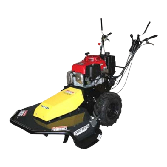
TRT 110‐135 /TRT 110‐135 Swing FUEL TANK CAP STARTER LEVER THROTTLE LEVER HANDLE BAR HEIGHT ADJUSTMENT RIGHT SIDE WHEEL LOCK BLADE ENGAGEMENT LEVER FORWARD MOVEMENT ADJUSTMENT GEARBOX LEVER FORWARD MOVEMENT ENGAGEMENT LEVER 10. LEFT SIDE WHEEL LOCK 11. SLOPE ADJUSTMENT LEVER (ONLY Swing VERSION) 12. MOTOR AIR FILTER 13. CUTTING HEIGHT ADJUSTMENT Figure 3‐2: Details TRT 110‐135 /TRT 110‐ 135 Swing OPERATIONAL PRINCIPLE 3.1.1 Intended Use The forestry mower shredder you have purchased was designed and manufactured for cutting grass/brambles/brush on uncultivated ground and underbrush, working in extreme conditions. ... -
Page 8: Vibrations
VIBRATIONS Operational Conditions: Motor RPM during tests 3000 rpm. TRT 60 / TRT 60 Swing TRT 110 / TRT 110 Swing / TRT 135 / TRT 135 Swing X 1.6 m/s² X 2.4 m/s² AEQ Y 2.2 m/s² AEQ Y 3.2 m/s² Z 4.1 m/s² Z 5.4 m/s² NOISE EMISSIONS The weighted equivalent continuous sound pressure level A in the work station is: TRT 60 / TRT 60 Swing TRT 110 / TRT 110 Swing / TRT 135 / TRT 135 Swing 93 dB (A) 95 dB (A) Other phonometric measurements in the workplace must be performed pursuant to what is provided for in the standards in force in the country of use. TECHNICAL SPECIFICATIONS TRT 60 TRT 60 Swing TRT 110 TRT 110 Swing TRT 135 TRT 135 Swing Motor Honda GCV 190 Honda GXV 340 Honda GXV 390 Honda GXV 160 Start up Recoil pull starter Transmission ... -
Page 9: Storage
ATTENTION! THE LIFTING POINT FOR THE FORK LIFT FORKS IS INDICATED IN THE FIGURE! STORAGE During long periods of storage of the machine it would be best to: Empty the fuel tank of fuel; Lubricate the cylinder with a suitable product, available at your reseller; Clean the air filter; Empty any residual gasoline from the carburettor; Grease any parts with the paint worn off by wear or impact of the machine and any parts where the treatment has worn off to avoid possible rust formation. PRELIMINARY CHECKS Check that all of the safety instruction adhesive labels are in order and legible. Check that the machine is cleaned of plant residue and debris. Check that all of the safety guards and grilles are in order and in good condition Before starting the motor Visually inspect for any leaks and/or defective, missing or worn parts. See to any necessary repairs before using the machine again. ... -
Page 10: Scrapping
SCRAPPING Proceed with the disassembly of the machine dividing its parts based on the materials with which they were manufactured. Follow the waste management and disposal standards in force. SAFETY GENERAL WARNINGS Inside of this manual and on the machine there are indications and printed messages together with the danger symbol shown below that indicate potential hazard. It would be best, therefore to pay close attention to what is shown or written in order to ensure greater safety for the operator and anyone else who might be in the operational range of the machine. Read this manual before using the machine. Only the instructions found in this manual will assist you in using the machine safely and efficiently. Safe usage is only the result of proper operation of the machine, in compliance with the standards and limitations described in this manual. Therefore, you must know and comply with all safety warnings in this manual and those relative to the proper operation of the machine. USE RESTRICTIONS ... -
Page 11: Signs
ATTENTION!!! Always keep the hands at a safe distance from the oscillating mechanism on the machine as it can easily crush the fingers. APPLICATION OF THESE REGULATIONS IS NOT A WASTE OF TIME! THESE REGULATIONS CONTRIBUTE TO KEEPING PERSONS AND THINGS FROM IRREPARABLE HARM AND ENSURE OPERATOR SAFETY. RESIDUAL RISKS Noise: always wear ear protection. Vibrations: these have been reduced by using anti‐vibration grips on the 110 and 135 models. It is recommended that one take regular breaks during work time. Do not use the machine for more than 8 hours in a day. MACHINE USE Dear customer, we thank you for the trust you have given ECOTECH ITALIA. We are confident that use of this new machine will fully fulfil your requirements. For the purpose of obtaining optimum application and efficient maintenance of the machine over time, please read all of the directions and warnings described in this booklet, which must always be kept together with the machine. BEFORE STARTING UP THE MACHINE READ THE USE INSTRUCTION MANUAL THOROUGHLY! ADJUSTMENTS Model Adjustment TRT 60 TRT 60 Swing TRT 110 TRT 110 Swing TRT 135 TRT 135 Swing Cutting ... -
Page 12: Operational Modes
(Figure 3‐1 n. 13) to corresponds to neutral and then so on to the first gear, second, third, fourth and fifth. increase or reduce the To move the machine with the motor off shift the lever to (Figure 3‐2 no. 8) the speed neutral position and activate the forward movement lever engagement (Figure 3‐2 no.9). Steering Use sufficient pressure on the hand grips to The machine is equipped with two levers, one on the left of the handle bar and the turn right or left. other on the right. These control the locking of the two wheel semi‐axles (Figure 3‐2 no. 5/ no. 10). Lightly activating these two levers, allows the corresponding wheel to turn freely, whilst the other continues as a drive wheel enabling the machine to make a large radius turn and to correct therefore the machine's trajectory in a smooth manner without jolts. Pulling the same lever to its full stroke instead acts on the locking of the wheel whilst the other continues as a drive wheel ensuring that the machine turns on itself when there is an obstacle or broken and unmanageable ground in front of it. Handlebar N/A The handlebars can be adjusted to five different heights. To adjust the height use the height right hand external lever (Figure 3‐2 no. 4) then adjust the corresponding pins in one of the five height adjustment holes (Figure 6‐1 no. 15) 15 ‐ Handlebar height adjustment pin 16 ‐ Handlebar end stroke screw Figure 6‐1: Handlebar height Slope N/A The machine enables three The machine The machine enables ... -
Page 13: Working On A Slope (Only On The Swing Version)
6.2.2 WORKING ON A SLOPE (only on the Swing version) TRT 60 Swing When working on sloping ground, it is necessary to widen the track of the wheels. To carry out this operation, raise the safety spring off of the pin and remove the pin (see figure). Slide out the semi‐axle and locate it in correspondence to the second hole, then replace the pin and the relative safety spring. Engage the parking brake located on top of the transmission casing. Figure 6‐4: Wheel locking pin TRT 60 At this point, unlock the motor, moving the lever on the handlebar backwards (Figure 6‐5: Handlebars no. 1), set the inclination angle of the machine according to the slope on the ground on which the work is to be done until the motor is on the level, horizontally, then lock the motor shifting the same lever forward. make sure that the locking pin (Figure 6‐6: Locking Pin) is positioned in one of the three seats to the right or to the left. Figure 6‐5: Handlebars Figure 6‐6: Locking Pin Now the machine is ready for work. To invert the working direction on the slope, unlock the lever (Figure 6‐7: Handlebars no. 1), hold it balanced with the handlebars rotate the machine 180 turning uphill, set the machine inclination angle on the opposite side, repositioning the motor on the level, then relocking the machine with the same lever and continuing the work in the ... -
Page 14: Normal Stop
At this point, unlock the motor, holding the left lever down on the handlebar (Figure 6‐10: Left handle bar no. 2), set the inclination angle of the machine according to the slope on the ground on which the work is to be done until the motor is on the level, horizontally, then lock the motor releasing the same lever in correspondence with one of the four positions. Figure 6‐10: Left handle bar Now the machine is ready for work. To invert the work direction on a slope the following sequence must be followed: release the forward movement lever (Figure 6‐10: Left handle bar no. 1), this way the machine is stopped and braked, position the motor in neutral (in this way the motor will be inclined for a few seconds together with the machine), engage the forward movement (Figure 6‐10: Left handle bar no. 1) and at the same time pull the uphill wheel locking lever all the way (Figure 6‐10: Left handle bar no. 3 or Figure 6‐12: Right handle bar no. 6), in this way the machine will turn 180° on itself toward the uphill side of the slope and will then be positioned in the opposite direction ready for work. Figure 6‐11: Left handle bar Figure 6‐12: Right handle bar Release the forward movement lever again (Figure 6‐10: Left handle bar no. 1), put the motor on the level again turning uphill, and at this point the machine is ready to start back to work in the opposite direction. ... -
Page 15: Cleaning
CLEANING ATTENTION!!! ABSOLUTELY DO NOT USE WATER JET CLEANING SYSTEMS. LUBRICATION Regularly lubricate/grease the mechanical components that actuate the moving parts of the machine: chains, gears, linkages, etc. For suitable lubricants, contact your reseller. ORDINARY MAINTENANCE Generally the oil level should be checked every 8 hours of running time, whilst the air filter should be cleaned every 4 hours, or even more often if working in a particularly dusty environment. Remove any cut grass deposits from the motor head to ensure better air flow. For proper use of the machine, do not ever force the motor; if white smoke begins to come out of the exhaust, it is necessary to slow down. EXTRAORDINARY MAINTENANCE Ask the reseller to perform these operations that require specific capabilities and equipment. Component to be Every 100 hours / Inspection Every 10 hours Every 50 hours checked year Check belt tension Blades belt Check belt wear Replace as necessary. ... -
Page 16: Diagnostics And Trouble Shooting
DIAGNOSTICS AND TROUBLE SHOOTING A. The motor does not start: make sure that: There is fuel in the tank (no. 10) The gas cock, if present, is not closed. With the engine cold, the gas lever must be on the START position (no. 9). With the motor hot, the gas lever should not be on the START position (this could flood the motor). The gas lever is not in the STOP position. Fuel reaches the carburettor. The air filter is not fouled (no. 13). The vent hole on top of the fuel cap is not clogged with debris (no. 10). The spark plug sparks. If these checks are positive but the motor does not start, contact your local reseller. ... -
Page 17: Spares And Accessories
The managers in the corporate departments who purchase this machine, have the obligation, pursuant to the standards in force, to read the contents of this Manual carefully and to have the assigned operators and maintenance personnel read it as regards the parts that concern them. The time used for this purpose will be for the most part compensated by the proper operation of the machine and by its safe use. This document assumes that wherever the machine is to be put into operation, that the work health and safety standards in force will be complied with. The instructions, drawings and documentation contained in this Manual are technical and confidential, being the property of ECOTECH ITALIA and may not be reproduced in any manner, either wholly or in part. The customer, in addition, has the responsibility to make sure that, in the event that this document were to be changed by the manufacturer, only updated versions of the manual will be actually available in the places where the machine is being used. The ECOTECH ITALIA Company is considered released from any liability in the case that the machine is used improperly, such as for example: Improper use of the machine or operation by untrained/unqualified personnel; Use in contrast with specific standards and legislation; Fuel supply defects; Serious deficiencies in maintenance; Unauthorised modifications or service procedures; ... -
Page 18: Glossary
INSTRUCTION MANUAL UPDATING METHODS ECOTECH ITALIA reserves the right to change the design in order to improve the machine without giving notice to customers, and without updating the manuals already delivered to end users. Therefore, in case of changes to machines installed in the customer's premises, as agreed to with the manufacturer and that bring about changes to one or more chapters of the Instruction Manual, it will be the manufacturer's responsibility to send the owners of the Instruction Manuals involved in the changes, with a new revised version of the same. It is the end user's responsibility, following the indications that accompany the updated documentation, to replace in all of the copies in their possession the old chapters with the new, the introductory page and the table of contents with the new revision. ECOTECH ITALIA is responsible for the descriptions given in the Italian language; any translations cannot be fully verified, therefore, if an incongruence were to take place, it is necessary to refer to the Italian language version and if necessary contact our sales offices, which will provide for any necessary changes. GLOSSARY In this section the uncommon terms, or those with a meaning different from the norm, will be listed. Below the abbreviations used are explained. 9.3.1 Glossary (Annex I p. 1.1.1 Dir. 2006/42/CE) DANGER: A potential source of injuries or damage to one's health and safety; ... - Page 19 Notified Body no. 1282: Ente Certificazione Macchine S.r.L. ‐ via Cà Bella 243, 40053 Loc. Castello di Serravalle – Valsamoggia (BO) ‐ ITALIA. La persona autorizzata a costituire il Fascicolo Tecnico Costruttivo è il Sig. Roberto Romboli presso ECOTECH ITALIA S.r.l. via Copernico, 85 47122 Forlì FC – ITALIA. Il Fascicolo Tecnico Costruttivo richiesto dalla Direttiva Macchine 2006/42/CE è conservato presso la sede dell’azienda. ...
- Page 20 HANDLEBAR MOUNTING SCHEME 1. Remove the 3 screws as in the pictures. 2. Turn the handlebar as in the picture. 3. Pull the lever. 4. Pull the handlebar forward. 5. Put again the 2 screws of handlebar. 6. Put again the screw.
- Page 21 7. Mount the handle gas. 8. Mount the gear lever 9. Turn the right levers and the left levers to the position as the 2 pictures. 10. Tighten the screws of right and left levers 11. Tighten with the band only the cable 12.
Need help?
Do you have a question about the TRT Series and is the answer not in the manual?
Questions and answers