Table of Contents
Advertisement
Quick Links
Advertisement
Table of Contents

Related Manuals for Medisoft Micro 5000


Summary of Contents for Medisoft Micro 5000
- Page 1 HARDWARE USER MANUAL Micro 5000 Version 2.2 H16-EN 30/12/2019...
-
Page 2: Table Of Contents
Calibration ......................21 Foreword ........................21 Preparing the equipment ..................21 Initializing the calibration mode ................22 Volume calibration ....................24 5.4.1 Calibrating the pneumotachograph .................... 24 5.4.2 Checking the pneumotachograph calibration ................30 Maintenance ......................32 H16-EN Micro 5000 2/35... - Page 3 Foreword ........................32 Maintenance planning ....................33 Maintenance procedures for the user ..............34 6.3.1 Cleaning ............................34 6.3.2 Replacement of the pneumotachograph mesh ................34 H16-EN Micro 5000 3/35...
- Page 4 Revision Date Version Modifications 16/06/2014 1.0 Creation 01/06/2018 2.0 New design 14/05/2019 2.1 Modification of the CE marking 30/12/2019 2.2 Removing redundant information’s H16-EN Micro 5000 4/35...
-
Page 5: Foreword
The handheld spirometer is suitable for spirometry in clinical context, pharmacology and epidemiology studies. The Micro 5000 is operated by ExpAir, a software program developed by Medisoft S.A. that functions on Windows based PC systems. -
Page 6: Description Of Available Tests
• Maximal voluntary ventilation test (MVV) • Minute tidal ventilation test (VE) Airway resistance The Micro 5000 device allows measuring the airway resistance by using the flow interruption techniques (Rint). This technique is based on measurement of mouth pressure during airflow occlusion. -
Page 7: List Of Standard And Optional Tests
1.3 List of standard and optional tests Standard/ SPIROMETRY Abbreviation optional Vital Capacity standard Forced Vital Capacity standard Maximum voluntary ventilation standard Minute tidal ventilation standard Reversibility (pre/post) standard Challenge (only software) standard MECHANICS Resistance by flow interruption RINT optional Maximal Inspiratory/Expiratory mouth Pressures MIP/MEP optional... -
Page 8: Warnings
2.1 Location of the device Location of the Micro 5000 The Micro 5000 module should not be located on wet or dusty conditions. The cooling ventilator on the rear panel must not be obstructed which could lead to an overheating inside the module. -
Page 9: Gas Cylinders
2.2 Gas cylinders If option NEP is available on your system, the Micro 5000 device requires one gas cylinder. Some recommendations have to be followed carefully in order to avoid any risk for the patient or the device. Localization of the gas cylinder Do not place a compressed gas cylinder near the device. -
Page 10: General Overview
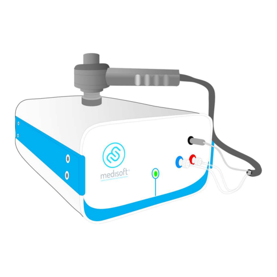
General overview 3.1 Front panel 3.1.1 Basic version Front panel Power LED Handheld spirometer Lilly type pneumotachograph Combined tubing for handheld spirometer Upstream flow connector (+, red) Downstream flow connector (-, blue) Heated wire connector Holder for pneumotachograph H16-EN General overview 10/35... -
Page 11: Provo 4 Option
3.1.2 Provo 4 option Front panel Power LED Handheld spirometer Lilly type pneumotachograph Combined tubing for handheld spirometer Upstream flow connector (+, red) Downstream flow connector (-, blue) Heated wire connector Holder for pneumotachograph Nebulizer Inlet for pressure measurement for nebulization triggering Outlet for nebulization pressure H16-EN General overview... -
Page 12: Rint, Mip/Mep, P01 Or Compliance Option
3.1.3 RINT, MIP/MEP, P01 or compliance option Front panel Power LED Handheld spirometer Lilly type pneumotachograph Combined tubing for handheld spirometer Upstream flow connector (+, red) Downstream flow connector (-, blue) Heated wire connector Holder for pneumotachograph Shutter Outlet for piston pressure supply H16-EN General overview 12/35... -
Page 13: Nep Option
3.1.4 NEP option Front panel Power LED Handheld spirometer Lilly type pneumotachograph Combined tubing for handheld spirometer Upstream flow connector (+, red) Downstream flow connector (-, blue) Heated wire connector Holder for pneumotachograph Venturi Outlet for Venturi pressure supply H16-EN General overview 13/35... -
Page 14: Snip Option
3.1.5 SNIP option Front panel Power LED Handheld spirometer Lilly type pneumotachograph Combined tubing for handheld spirometer Upstream flow connector (+, red) Downstream flow connector (-, blue) Heated wire connector Holder for pneumotachograph Catheter SNIP H16-EN General overview 14/35... -
Page 15: Rear Panel
3.2 Rear panel Rear panel Cooling fan Serial communication port (connected to computer) Thermometer sensor Humidity sensor Power switch (ON/OFF) Power supply entry Gas inlet for nebuliser (Provo 4 option) or piston supply (MIP/MEP, RINT, P01 or NEP option) H16-EN General overview 15/35... -
Page 16: Handheld Pneumotachograph
3.3 Handheld pneumotachograph Pneumotachograph front part (patient facing) Heated wire and plug Pneumotachograph mesh Handle Pneumotachograph back part (to ambient) Antibacterial/viral filter Shutter for MIP/MEP, RINT or P01 Upstream flow line and connector (+, red) option Downstream flow line and connector (-, blue) Venturi for NEP option H16-EN General overview... -
Page 17: Connections
Connections 4.1 Connections on the front panel 4.1.1 All versions Insert the plug-in connectors to the upstream (red)/downstream (blue) ports Secure the connection by clockwise rotation of the plug-in connectors Plug the heated wire H16-EN Connections 17/35... -
Page 18: Provo 4 Option
4.1.2 Provo 4 option Connection to pressure measurement for nebulization triggering Connection for nebulization pressure 4.1.3 MIP/MEP or RINT option Connection for piston pressure supply H16-EN Connections 18/35... -
Page 19: Nep Option
4.1.4 NEP option Connection for Venturi pressure supply 4.1.5 SNIP option Upstream flow connector (+, red) Downstream flow connector (-, blue) H16-EN Connections 19/35... -
Page 20: Connections On The Rear Panel
4.2 Connections on the rear panel Power supply cable Serial communication cable For Provo 4, MIP/MEP, P01, RINT or compliance option Connection to compressor (3.5 bar – 50 psi) For NEP option Connection to compressed air bottle (6 bar – 87 psi) H16-EN Connections 20/35... -
Page 21: Calibration
After a calibration, it is possible to perform a check (which is recommended by ATS-ERS guidelines) in order to verify the quality of the calibration and the accuracy of the measurement. The table below summarises the calibrations which have to be performed on Micro 5000 module. Calibration Min. -
Page 22: Initializing The Calibration Mode
5.3 Initializing the calibration mode On main menu of Expair, select the calibration menu Click on New Check ambient conditions and correct if necessary Define operator’s name H16-EN Calibration 22/35... - Page 23 The ambient conditions are used to calculate BTPS correction factor. It is essential that ambient conditions are measured or encoded correctly for accurate volume measurement: • Temperature: in degrees Celcius • Relative humidity: in % • Barometric pressure: in mmHg Important information on barometric pressure The barometric pressure used by the software is the actual barometric pressure, not barometric pressure corrected at sea level.
-
Page 24: Volume Calibration
5.4 Volume calibration 5.4.1 Calibrating the pneumotachograph Calibration process H16-EN Calibration 24/35... - Page 25 Select the Volume tab. Select the device (if there are several modules connected to the same computer). Define the calibration syringe volume (by default, it is set to 3 liters). Click on Calibrate. Wait for the zero measurement (red cross). When the green check mark is displayed, the device is ready to calibrate.
- Page 26 Analysis of the volume calibration results Analysis of the calibration results is essential to ensure an accurate volume measurement by the system. Flow-volume loop During the calibration process, the flow-volume loops are displayed, the volume is on the horizontal axis and the flow is on the vertical axis. There should be no drift on the horizontal axis as shown below.
- Page 27 Verification of the system If one or two traffic lights are yellow or red, the operator has to perform a verification of the system described below. 1. Verify the connection of the tubing to the module (red and blue connectors). 2.
- Page 28 3. Verify the pneumotachograph is assembled correctly and fitted securely to the handle. 4. Verify the correct syringe volume (indicated on a label on the syringe) is the same volume entered into the software. 5. Verify the calibration syringe is not damaged and has no leak. Calibration syringes should ideally be checked and calibrated annually by a calibration laboratory.
- Page 29 Deviation between 5 and 10%. The calibration is acceptable and the system can be used. The deviation could be a sign that device maintenance is necessary. Please contact your Medisoft representative. Deviation greater than 10%. The calibration is not acceptable. A verification of the system by a field service technician is required.
-
Page 30: Checking The Pneumotachograph Calibration
5.4.2 Checking the pneumotachograph calibration As the respiratory flow patterns are made up of many different flows, an individual flow error will affect the overall result. The calibration can be verified at multiple flow rates with the use of the Check button. This allows the operator to check different flow rates and to ensure the quality of the volume measurement linearity or that the readings are good over the full operating range of the pneumotachograph. - Page 31 ATS-ERS criteria. The system can be used. Accuracy greater than 3.5%. The linearity of the volume measurement is not good and does not meet ATS-ERS criteria. A verification of the system linearity by a field service technician is required. Please contact your Medisoft representative. H16-EN Calibration...
-
Page 32: Maintenance
Maintenance 6.1 Foreword All Medisoft devices are designed to have a lifetime of 10 years minimum, which entails a regular maintenance to be performed by the manufacturer or its representative. The device requires a preventive maintenance once a year, along with a recommended bi-annual control visits in order to validate the calibration. -
Page 33: Maintenance Planning
6.2 Maintenance planning Table below shows the list of actions to be performed for a full preventive maintenance. Each action has to be performed by the user or a technician approved by Medisoft or its representative. The highlighted actions have to be performed by the user by following the procedures described in the next paragraphs. -
Page 34: Maintenance Procedures For The User
6.3 Maintenance procedures for the user 6.3.1 Cleaning See dedicated manual for cleaning and disinfection. 6.3.2 Replacement of the pneumotachograph mesh Remove the pneumotachograph from the handle. Take the pneumotachograph from the lower part and turn counter clockwise the upper part in order to disassemble the pneumotachograph. Carefully remove the mesh. - Page 35 Medisoft S.A. www.medisoft.be P.A.E. de Sorinnes info@medisoft.be 1, Route de la Voie Cuivrée T: +32 (0)82 22 30 20 5503 Dinant – Sorinnes (Belgium) F: +32 (0)82 22 33 34...
Need help?
Do you have a question about the Micro 5000 and is the answer not in the manual?
Questions and answers