Table of Contents
Advertisement
Quick Links
CODEL
Page 1
Operation and Maintenance
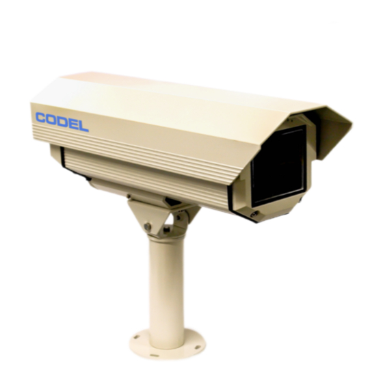
TunnelTech 601 Luminance Photometer
Operation and Maintenance Manual
CODEL International Ltd.
Station Building, Station Road, Bakewell, Derbyshire DE45 1GE United Kingdom
t : +44 (0) 1629 814 351
f : +44 (0) 8700 566 307
e : codel@codel.co.uk
web : www.codel.co.uk
Issue: A
Revision:
Date: 10/10/18
Ref: 100533
Advertisement
Table of Contents

Related Manuals for CODEL TunnelTech 601


Summary of Contents for CODEL TunnelTech 601
- Page 1 CODEL Page 1 Operation and Maintenance TunnelTech 601 Luminance Photometer Operation and Maintenance Manual CODEL International Ltd. Station Building, Station Road, Bakewell, Derbyshire DE45 1GE United Kingdom t : +44 (0) 1629 814 351 f : +44 (0) 8700 566 307 e : codel@codel.co.uk...
- Page 2 CODEL Page 2 Operation and Maintenance Issue: A Revision: Date: 10/10/18 Ref: 100533...
- Page 3 Page 3 Operation and Maintenance CODEL International Ltd is a UK company based in the heart of the Peak District National Park at Bakewell, Derbyshire. The company specialises in the design and manufacture of high-technology instrumentation for the monitoring of combustion processes and atmospheric pollutant emissions.
- Page 4 CODEL Page 4 Operation and Maintenance Issue: A Revision: Date: 10/10/18 Ref: 100533...
-
Page 5: Table Of Contents
CODEL Page 5 Operation and Maintenance Contents System Description ......................... 1 The TunnelTech 601: ....................... 1 Optional accessories ....................... 1 Principles of Operation ........................2 Specification ............................ 3 Sensor............................3 Housing ........................... 4 Certifications ........................... 4 Installation ............................5 Device Location ........................5 Unit Installation ........................ - Page 6 CODEL Page 6 Operation and Maintenance Issue: A Revision: Date: 10/10/18 Ref: 100533...
- Page 7 CODEL Page 7 Operation and Maintenance IMPORTANT The warning signs (and meanings) shown below, are used throughout these instructions and are intended to ensure your safety while carrying out installation, operation and maintenance procedures. Please read these instructions fully before proceeding.
- Page 8 CODEL Page 8 Operation and Maintenance Issue: A Revision: Date: 10/10/18 Ref: 100533...
-
Page 9: System Description
A signal output from the TunnelTech 601 is fed to a suitable controller to adjust the level of light intensity inside the road tunnel to the light intensity outside, The TunnelTech 601 Luminance Photometer fully complies with CIE recommendations for road tunnel lighting control. -
Page 10: Principles Of Operation
Operation and Maintenance 2 Principles of Operation The TunnelTech 601 is built around a metal/glass encased reverse biased silicon diode photocell that determines the luminance levels of a given area, together with an eye response optical filter with a 20° viewing angle. Optical filters are used to provide measurements of luminance to the required standard human visible spectral response. -
Page 11: Specification
CODEL Page 3 Operation and Maintenance 3 Specification 3.1 Sensor Sensor type Silicon Photocell with eye response filter. 20° viewing angle Measurement cd/m². Standard measurement range 0-6500 cd/m². (max range 0-10000 cd/m² available on request) Calibration Tracible to British National Physics Laboratory NPL Ref. -
Page 12: Housing
CODEL Page 4 Operation and Maintenance 3.2 Housing Material Extruded aluminium, Epoxypolyester powder paint and RAL9002 colour stainless steel external screws Dimensions L: 493mm W:175mm H:168mm weight 4.5kg weatherproofing Weatherproof standard IP66; Solar protection provided by extruded aluminium sunshield, Thermostatically controlled heater element (12 watt consumption). -
Page 13: Installation
CAUTION! Device installation must be performed by specialist technical staff only. 4.1 Device Location The TunnelTech 601 enclosure can be mounted on a purpose-built mounting platform or fastened to an existing column, wall or other mounting surface in the same manner that any other electrical surveillance device. -
Page 14: Unit Installation
4 times the weight of the device is applied. The pan/tilt bracket allows the TunnelTech 601 to be panned through a 360° lateral angle and tilted vertically through ±120°. The main device housing is attached to the tilt/pan bracket via two M6x12mm 10mm hex head bolts and m6 washers, supplied with the bracket. -
Page 15: Cable Installation
CODEL Page 7 Operation and Maintenance 4.3 Cable installation Before starting any installation, ensure that the power supply Is disconnected. Never under any circumstances make any changes or connection that are not shown in this manual. Improper use of the appliance can cause serious hazards, risking the safety of personnel and of the installation. - Page 16 CODEL Page 8 Operation and Maintenance Figure 6: Luminance Amp and Current Driver PCB CAUTION! The type of cable used must be compatible with the planned use and comply with the national regulations in force on electrical installation. connect the signal output cable to the TB2 terminal (marked Sig) on the Luminance Amplifier and Current Driver PCB, paying attention to the + and –...
-
Page 17: Optional 24V Dc Power Supply Unit (Psu) Installation
CODEL Page 9 Operation and Maintenance 4.4 Optional 24V DC Power Supply Unit (PSU) Installation Mount the PSU to the mounting surface using 4 M6 bolts (by others). Mounting hole details are shown in Figure 7 below Figure 7: Optional PSU mounting Arrangement Make sure the PSU enclosure is earthed with a grounding strap during installation using the earthing bolt. -
Page 18: Maintenance
CODEL Page 10 Operation and Maintenance 5 Maintenance Recalibration checks: The silicone receptor is extremely stable over a long period. Recalibration checks are not normally necessary within ten-year periods. Maintenance: Minimal. Occasional cleaning of the viewing window. (Not necessary if automatic Wash/Wipe unit is fitted, available upon request). -
Page 19: Ma Output
Operation and Maintenance 6 mA Output the output of the TunnelTech 601 is a standard 4- 20mA current loop. The response from the sensor is perfectly linear within the calibrated range of 0 to 6500 cd/m² and therefore the mA output is delivered accordingly and is updated near constantly. -
Page 20: List Of Figures
CODEL Page 12 Operation and Maintenance 7 List of Figures Figure 1: positioning ..........................5 Figure 2: Enclosure Dimensions ......................6 Figure 3: Bracket dimensions ........................6 Figure 4: enclosure disassembly ......................7 Figure 5: Power Distribution and Heater Control PCB ................7 Figure 6: Luminance Amp and Current Driver PCB .................
Need help?
Do you have a question about the TunnelTech 601 and is the answer not in the manual?
Questions and answers