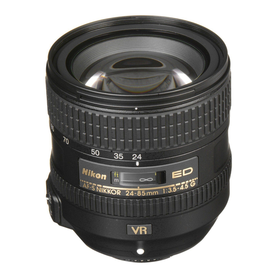
Summary of Contents for Nikon AF Nikkor 24-85
- Page 32 JAA77451-R.3512.A - A16-1・ AF24-85/2.8-4D - Added page February. 14. 2005...
- Page 33 JAA77451-R.3512.A Back view of Lens optical alignment equipment ・ Connect each cable to the appropriate equipment with the same number. (e.g. Connect up ① to‘ ① ) ① VIDEO cable ‘ ① VIDEO IN ② VIDEO OUT ‘ ② "VIDEO IN"...
- Page 34 JAA77451-R.3512.A (2) Temporary positioning of Rear lens group ① Mount the (self-made) center positioning tool on the lens alignment equipment (for periphery) with the groove positioned slightly toward the counterclockwise direction from the below 12 o’clock position. Then turn the tool clockwise all the way to the right, and move the lever to the left to fix it. Fixing lever Groove for release pin Center positioning tool...
- Page 35 JAA77451-R.3512.A - A16-4・ AF24-85/2.8-4D - Added page February. 14. 2005...
- Page 36 JAA77451-R.3512.A - A16-5・ AF24-85/2.8-4D - Added page February. 14. 2005...
- Page 37 JAA77451-R.3512.A 30 cm - A16-6・ AF24-85/2.8-4D - Added page February. 14. 2005...
- Page 38 JAA77451-R.3512.A Back Front Connect the PC and camera via USB cable. (Camera setting: Mass Storage) ⑧ Start the adjustment software (LWM.exe) ⑨ Click the "Reset all log" button. ⑩ “ - A16-7・ AF24-85/2.8-4D - Added page February. 14. 2005...
- Page 39 JAA77451-R.3512.A ⑫ Set the indication pointer of the tripod to 30 cm. "Focusing" (Revision) � � Click the "adjustment" button to activate the AF and the shutter will be released. ⑭ Check that the shape of shot 8 point images (as shown below) becomes as perfect as circle. ※...
- Page 40 JAA77451-R.3512.A - A16-9・ AF24-85/2.8-4D - Added page February. 14. 2005...
- Page 41 JAA77451-R.3512.A Note 1: When the below warning is given, there may be some defects in the brightness of the viewers and/or parallelism of the chart and camera, etc. So correct the above and make a remeasurement. Note 2: When the below warning is given, recheck that the Quality mode of the camera is set to RAW. Note 3: When the below warning is given, recheck that the zoom ring of the lens is set to TELE-end.
- Page 42 JAA77451-R.3512.A After the 7 measurements, point the cursor to the confirmation screen of the software. Click it 3 times, and ⑲ if "END" is displayed on the Information, the lens optical alignment is completed. If "END" is NOT displayed, go to the next “(4) Rear lens group alignment” to readjust. - A16-11 ・...
- Page 43 JAA77451-R.3512.A (4) Rear lens group alignment ① Mount the lens in the equipment (for center). (ref. ① of (2) for how to fit in it.) ② Turn the power of the monitor, LINE GENERATOR, and MEGALIGHT100 to ON. ③ Press the "LINE ON/OFF" button of LINE GENERATOR. Turn the knobs of “X1” and “Y1” so that X- and Y-lines are displayed on the monitor.
- Page 44 JAA77451-R.3512.A ④ Unlock the holder-moving lever, and move the holder down slowly by the lever. ⑤ Insert the alignment screwdrivers (long, middle, short) into the screw holes of the 5th lens chamber, and loosen the 3 screws. ⑥ Rotate the micrometers (X and Y), and shift the cross lines by the scales that were results of the chart shooting of the 5th lens group alignment.
- Page 45 JAA77451-R.3512.A How to create positioning tool of rear-lens-group holder for lens alignment 1: Summary 1-1: This is a positioning tool of the rear lens group holder for lens alignment, in order to secure the position for attaching the rear lens group temporarily.
- Page 46 JAA77451-R.3512.A 3-3: Turn the rear cover ring clockwise, which was attached to the bayonet mount. Then stop at the position as shown in Fig.3-1. Fig. 3 Fig. 3-1 3-4: Fix the following 3 locations of the rear cover ring with the instant adhesive. Fig.
- Page 47 JAA77451-R.3512.A How to create Setting board of "Lens alignment chart" and "Viewer" 1. Summary 1-1: In order to get necessary data for lens alignment, this board is created to use for setting a special chart and light viewers (for chart illumination), while taking pictures of the special chart with a digital camera. 2.
- Page 48 JAA77451-R.3512.A (Fig. 1- Prepare 2 package cardboard (Fig. 2 - As for the 1st flattened cardboard box, cut out the boxes, and flatten them as below.) <154 x 245 mm sized> shape at 5 locations.) (Fig. 3- Package cardboard boxes) (Fig.


Need help?
Do you have a question about the AF Nikkor 24-85 and is the answer not in the manual?
Questions and answers