Table of Contents
Advertisement
SERVICE MANUAL
Ver. 1.1 2011.12
System
Laser: Semiconductor laser
Inputs and outputs
(Jack name:
Jack type/Output level/Load impedance)
LINE OUT R-AUDIO-L:
Phone jack/2 Vrms/10 kilohms
DIGITAL OUT (COAXIAL):
Phono jack/0.5 Vp-p/75 ohms
HDMI OUT:
HDMI 19-pin standard connector
LINE OUT VIDEO:
Phono jack/1.0 Vp-p/75 ohms
LAN (100):
100BASE-TX Terminal
USB:
USB jack Type A (For connecting a USB
memory, memory card reader, digital still camera
and digital video camera)
Wireless
Wireless LAN standard:
IEEE 802.11 b/g/n
Frequency range:
2.4 GHz band : Channels 1-13
Modulation:
DSSS and OFDM
This product meets ENERGY STAR guidelines for energy
are registered U.S. marks. ENERGY STAR is a registered
mark owned by the U.S. government.
(BDP-S390:US,CND/BX39:US,CND)
9-890-769-12
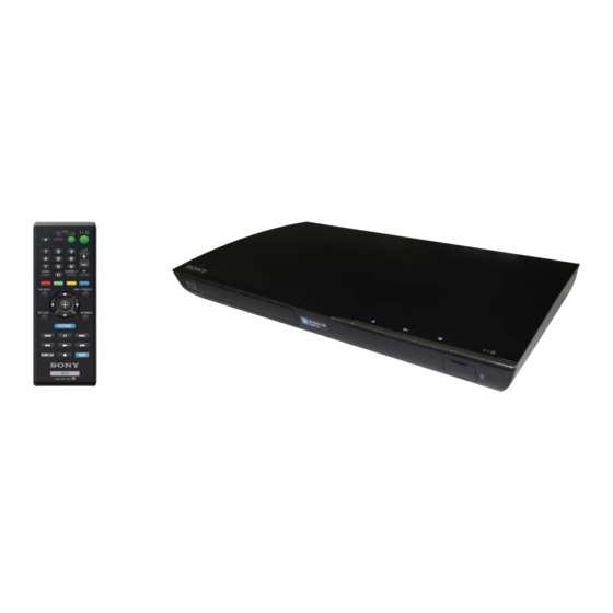
Photo : BDP-S390
Remote : RMT-B119P
SPECIFICATIONS
®
Sony Corporation
Home Entertainment Business Group
BDP-S390/BX39
RMT-B119A/B119P/B120A
General
Power requirements:
110V – 240V AC, 50/60Hz (S390:E,MX)
120V AC, 60Hz (BDP-BX39/S390:US,CND)
220V – 240V AC, 50/60Hz (BDP-BX39/S390:UK,AEP,AUS,RUS)
Power consumption:
11 W
Dimensions (approx.):
5
7
3
12
x 1
320mm × 200mm × 43mm
8
8
4
(width/depth/height) incl. projecting parts
Mass (approx.):
1.2kg (2 lb 10 oz)
Operating temperature:
5 ºC to 35 ºC (4 1 ºF to 95ºF )
Operating humidity:
25 % to 80 %
Supplied accessories
• Audio/video cable (phono plug ×3) (1) (BDP-BX39/S390:US,CND,AUS,RUS)
• HDMI cable (1)(BDP-BX39/S390:MX,E)
Plug adapter (1) (BDP-S390:MX,E)
•
• Remote commander (remote) (1)
Size AA (R6) batteries (2)
•
Specifications and design are subject to change
without notice.
Blu-ray Disc™ / DVD Player
Published by Document Design Dept.
UK Model
AEP Model
Russian Model
Australia/NZ Model
Mexican Model
Latin America Model
BDP-S390
US Model
Canadian Model
BDP-S390/BX39
2011K6900-1
© 2011.12
Advertisement
Table of Contents

Related Manuals for Sony RMT-B119A


Summary of Contents for Sony RMT-B119A
- Page 1 BDP-S390/BX39 RMT-B119A/B119P/B120A SERVICE MANUAL UK Model AEP Model Russian Model Australia/NZ Model Mexican Model Ver. 1.1 2011.12 Latin America Model BDP-S390 US Model Canadian Model BDP-S390/BX39 Photo : BDP-S390 Remote : RMT-B119P SPECIFICATIONS System General Laser: Semiconductor laser Power requirements: Inputs and outputs 110V –...
- Page 2 CRITIQUES POUR LA SÉCURITÉ DE FONCTIONNEMENT. NE ordinary solder so use caution not to let solder bridges occur such REMPLACER CES COMPOSANTS QUE PAR DES PIÈSES SONY as on IC pins, etc. DONT LES NUMÉROS SONT DONNÉS DANS CE MANUEL OU •...
-
Page 3: Table Of Contents
BDP-BX39/S390 TABLE OF CONTENTS SERVICE NOTE 4-11. MB-144 Board (HDMI/VIDEO) 1-1. Disc Removal Procedure If The Tray Cannot Be Schematic Diagram (7/12) .......... 4-11 Ejected (Forced Ejection) ..........1-1 1-2. Work when optical device are replaced ....... 1-1 4-12. MB-144 Board (ETHERNET) 1-3. -
Page 4: Service Note
BDP-BX39/S390 SECTION 1 SERVICE NOTE 1-1. DISC REMOVAL PROCEDURE IF THE TRAY CANNOT BE EJECTED (FORCED EJECTION) 1. Remove the side panel left. (Refer to page 2-1) 2. Insert a clip in the hole of a drive and open a tray. Tray cover out Tray cover out 1 Insert a clip in the hole of a drive... -
Page 5: Test Disc
BDP-BX39/S390 1-3. TEST DISC Part No. Description Layer J-6090-199-A BLX-104 Single Layer J-6090-200-A BLX-204 Dual Layer J-2501-307-A CD (HLX-A1) J-2501-305-A HLX-513 Single Layer (NTSC) J-2501-306-A HLX-514 Dual Layer (NTSC) J-6090-077-A HLX-506 Single Layer (PAL) J-6090-078-A HLX-507 Dual Layer (PAL) 1-3-1. Operation and Display Check Items 1) BLX-104 1. - Page 6 BDP-BX39/S390 1-3-1-1. BLX-104 Menu Function (1) Main Menu 1) When the disc is inserted, 1. Video Signal of 59.94Hz/1080i of the Main Menu is selectively displayed. 1-3-1-2. BLX-104 Menu Function (2) Main Menu To Main Menu after playback of T62_C1 To Main Menu after playback of T61_C1 To Main Menu after playback from T54_C1 to T60_C1 Sub_menu3 is displayed...
- Page 7 BDP-BX39/S390 1-3-1-3. BLX-104 Menu Function (3) Main Menu To Main Menu after playback of T52_C1 To Main Menu after playback of T51_C1 To Main Menu after playback from T44_C1 to T50_C1 Sub_menu2 is displayed To Main Menu after playback of T42_C1 To Main Menu after playback of T41_C1 To Main Menu after playback from T23_C1 to T40_C1 Sub_menu4 is displayed...
- Page 8 BDP-BX39/S390 1-3-1-4. BLX-104 Menu Function (4) Sub menu1 1) At the display of Sub menu1, 1. Color Bar 100% is selectively displayed. 2) Selection of 1. Color Bar 100% t Return to Sub menu1 after seamless playback from T1_C1 to T1_C13. 1. Color Bar 100% is selec- tively displayed on Sub menu1 screen.
- Page 9 BDP-BX39/S390 1-3-1-5. BLX-104 Menu Function (5) Sub menu2 1) At the display of Sub menu2, 1. Color Bar 100% is selectively displayed. 2) Selection of 1. Color Bar 100% t Return to Sub menu2 after seamless playback from T43_C1 to T43_C13. 1. Color Bar 100% is selectively displayed on Sub menu2 screen.
- Page 10 BDP-BX39/S390 1-3-1-6. BLX-104 Menu Function (6) Sub menu3 1) At the display of Sub menu3, 1. Color Bar 100% is selectively displayed. 2) Selection of 1. Color Bar 100% t Return to Sub menu3 after seamless playback from T53_C1 to T53_C13. 1. Color Bar 100% is selectively displayed on Sub menu3 screen.
- Page 11 BDP-BX39/S390 1-3-1-7. BLX-104 Menu Function (7) Sub menu4 1) At the display of Sub menu4, 1. Color Bar 100% is selectively displayed. 2) Selection of 1. Color Bar 100% t Return to Sub menu4 after seamless playback from T22_C1 to T22_C13. 1. Color Bar 100% is selectively displayed on Sub menu4 screen.
- Page 12 BDP-BX39/S390 1-3-2 Menu Function 1-3-2-1. BLX-204 Menu Function (1) Main Menu 1) When the disc is inserted, 1. Video Signal of 59.94Hz/1080i of the Main Menu is selectively displayed. 1-3-2-2. BLX-204 Menu Function (2) Main Menu To Main Menu after playback of T83_C1 To Main Menu after playback of T62 t T82 To Main Menu after playback of T61_C1 To Main Menu after playback of T54_C1-T60_C1 t T83_C1-T94_C1...
- Page 13 BDP-BX39/S390 1-3-2-3. BLX-204 Menu Function (3) Main Menu To Main Menu after playback of T70_C1 To Main Menu after playback of T52_C1 T69 To Main Menu after playback of T51_C1 To Main Menu after playback of T44_C1-T50_C1 T71_C1-T81_C1 Sub_menu2 is displayed To Main Menu after playback of T68_C1 To Main Menu after playback of T42_C1 To Main Menu after playback of T41_C1...
- Page 14 BDP-BX39/S390 1-3-2-4. BLX-204 Menu Function (4) Sub menu 1 1) At the display of Sub menu1, 1. Color Bar 100% is selectively displayed. 2) Selection of 1. Color Bar 100% t Return to Sub menu1 after seamless playback from T1_C1 to T1_C13. 1. Color Bar 100% is selec- tively displayed on Sub menu1 screen.
- Page 15 BDP-BX39/S390 1-3-2-5. BLX-204 Menu Function (5) Sub menu 2 1) At the display of Sub menu2, 1. Color Bar 100% is selectively displayed. 2) Selection of 1. Color Bar 100% t Return to Sub menu2 after seamless playback from T43_C1 to T43_C13. 1. Color Bar 100% is selectively displayed on Sub menu2 screen.
- Page 16 BDP-BX39/S390 1-3-2-6. BLX-204 Menu Function (6) Sub menu 3 1) At the display of Sub menu3, 1. Color Bar 100% is selectively displayed. 2) Selection of 1. Color Bar 100% t Return to Sub menu3 after seamless playback from T53_C1 to T53_C13. 1. Color Bar 100% is selectively displayed on Sub menu3 screen.
- Page 17 BDP-BX39/S390 1-3-2-7. BLX-204 Menu Function (7) Sub menu 4 1) At the display of Sub menu4, 1. Color Bar 100% is selectively displayed. 2) Selection of 1. Color Bar 100% t Return to Sub menu4 after seamless playback from T22_C1 to T22_C13. 1. Color Bar 100% is selectively displayed on Sub menu4 screen.
-
Page 18: Drive Repairing
BDP-BX39/S390 - 1 DRIVE REPAIRING 1-4-1. Preparation • ESD Measures It is necessary to check the working space ESD condition before starting the Drive Part (BU) repairs. The ESD-resistance of BD Laser is weaker than DVD/CD Laser To prevent ESD destruction, please make sure the working space and human ESD. -
Page 19: Bu Check Flow [Zz]
BDP-BX39/S390 1-4-3. BU Check Flow [zz] ~ Before BU Replacement Optical Block Unit (BU) IOP check flow (zz) ~ [Before BU Replacement] Enter Service Mode Press <OPEN/CLOSE>., <PLAY>,<STOP> and plug in AC Power Inside *Service Mode Menu Select [8] Drive Inside *Drive Select [7] OP Check Menu Inside *OP Check Menu... -
Page 20: Bu Adjustment Flow [Yy]
BDP-BX39/S390 1-4-5. BU Adjustment Flow [yy] ~ Explanation: Mode 1: BDV set Select mode: 1 or 2 Mode 2: BDP-BX39/S190/S390 1-4-6. KEM480AAA/C2RP1 Packing Spec. KEM480AAA/C2RP1 KEM-480AAA/C2RP1 Packing Spec. Packing Spec. ① ② ③ Open a box Take a top covered cushion out ④... -
Page 21: Kem480Aaa/C2Rp1 Packing
BDP-BX39/S390 1-4-7. KEM480AAA/C2RP1 Packing Lid foam tray (480RP) Antistatic bag 1) 1 piece of BU is put into “Bag,Charge Prevention” and excess part of bag is folded back. Mechanical deck 2) The BU and Manual instruction are put into Tray (PSFM) and lid is put on it. -
Page 22: Bu Data Decode Jig
BDP-BX39/S390 1-4-8. BU Data Decode Jig ・ JIG Name : BDPRdec.exe ・ Release : 2011.8.25 ・ Version : 3.0.0.0 ・ Software Contents BDPRdec.exe ; Software (initial destination is C:\BuData.txt) TasmanBars.dll ; decode dll Uninst.exe ; unregistration BDPRdec.exe from PC ・ Installations 2.Check the attached 2D code photo(OK_sample.JPG) drag-and-drop onto BDPRdec.exe, the 3.If there is the error message (.NET frame work requirements) please apply... -
Page 23: Loading For Service
BDP-BX39/S390 1-4-9. Loading For Service BDP 7G Loading Assy service parts consists from 2 parts. ① Holder, Clamper Assy ② Loading Assy ① and ② DO NOT COMBINE Currently these parts are producing by 2 vendors. Please (From diferent vendor) because THERE IS NO COMPATIBILITY. - Page 24 BDP-BX39/S390 In case of BU assy replacement: 1. OP related data for new assy is controlled by BU factory 2. All of data is recorded into a barcode label 3. The label is put on the assy 4. Service parts will be followed 5.
- Page 25 BDP-BX39/S390 1-4-10. Laser caution label Save the TEXT data Shoot the barcode Format is JPEG Application Software USB device is connected Data convert from symbol on the JPEG TEXT rear unit, and the TEXT data as new data is loaded to unit by service mode.
-
Page 26: Assembly Caution
BDP-BX39/S390 1-5. ASSEMBLY CAUTION 1-5-1. Whenever you need to disassemble or assemble the PS Insulator please handle it with care, since it might be broken and not a service part. 1-5-2. Whenever you need to disassemble or assemble MB-144 board, please make sure the radiation sheet is at the right place, since it might be rippedand not a service part. -
Page 27: Disassembly
BDP-BX39/S390 SECTION 2 DISASSEMBLY • This set can be disassembled in the order shown below. 2-1. DISASSEMBLY FLOW 2-2. SIDE PANEL (Page 2-1) 2-3. TRAY COVER ASSY (Page 2-2) 2-4. TOP PANEL (Page 2-2) 2-6. SWITCHING 2-8. BD DRIVE 2-5. FR-318 boards 2-7. -
Page 28: Tray Cover Assy
BDP-BX39/S390 2-3. TRAY COVER ASSY 1 Insert a clip in the hole of a drive to open a tray. 3 Tray cover assy Tray 2-4. TOP PANEL Top Panel Five hook... -
Page 29: Board And Wlan Module
BDP-BX39/S390 2-5. FR-318 BOARD AND WLAN MODULE USB-023 PM-173 PM-173 *Caution Whenever you need to assemble WLAN module please make sure harness USB-023 and PM-173 is at the right place. Harness USB-023 (CNxxx) WLAN Module One screws +BV3(3-CR) (tightening torque = 5 to 6 kgf•cm) *Caution Whenever you need to assemble FR-318 Flexible flat... -
Page 30: Drive
BDP-BX39/S390 2-7. MB-144 BOARD Three screw s +BV3(3-CR) Flexibl e fla t cable (SPD-005) (tightening torque = 5 to 6 kgf•cm) (CN1260) Shield Case Flexibl e fla t cable (OPT-005) (CN1101) One screw +P 3x3 Flexibl e fla t cable (LDG-003) (tightening torque = 3 to 4 kgf•cm) (CN1270) One screw (Black) +BV3(3-CR) -
Page 31: Board (Clk/Power2)
BDP-BX39/S390 2-9. CIRCUIT BOARDS LOCATION MB-144 board WLAN Module FR-318 Board Switching regulator 2-5E... -
Page 37: Schematic Diagram (4/12)
BDP-BX39/S390 SECTION 4 SCHEMATIC DIAGRAMS 4-1. THIS NOTE IS COMMON FOR SCHEMATIC DIAGRAMS All capacitors are in F unless otherwise noted. pF : 50V or less are not indicated except for electrolytics and tantalums. All resistors are in ohms, 1/4 W (Chip resistors : 1 /10 W) un-less otherwise specified. -
Page 40: Board (Usb) Schematic Diagram
BDP-BX39/S390 4-4. FR-318 BOARD (USB FRONT) SCHEMATIC DIAGRAM • See page 5-2 for printed wiring board. - Ref. No.: FR-318 board; 20,000 series - FR-318 BOARD... -
Page 53: Waveforms
BDP-BX39/S390 4-17. WAVEFORMS MB-144 BOARD (NS_XTALI) IC101 (VDACX_OUT) IC101 3.3 Vp-p 2.4 Vp-p 27 MHz 4-17E... -
Page 54: Printed Wiring Boards
BDP-BX39/S390 SECTION 5 PRINTED WIRING BOARDS 5-1. THIS NOTE IS COMMON FOR PRINTED WIRING BOARDS • : Uses unleaded solders. • : Pattern from the side which enables seeing. (The other layers’ patterns are not indicated) Caution: Pattern face side: Parts on the pattern face side seen from (SIDE B) the pattern face are indicated. -
Page 58: Ic Pin Function Description
BDP-BX39/S390 SECTION 6 IC PIN FUNCTION DESCRIPTION MAIN SYSTEM CONTROL PIN FUNCTION (MB-144 BOARD IC 101 : CXD90007G-AB) Symbol Type Description DVCC12_K Power 1.2V digital power DVCC12_K Power 1.2V digital power DVCC12_K Power 1.2V digital power DVCC12_K Power 1.2V digital power DVCC12_K Power 1.2V digital power... - Page 59 BDP-BX39/S390 AB13 DGND12_K Ground Digital ground AC18 DGND12_K Ground Digital ground DVCC33_IO Power 3.3V Digital IO power DVCC33_IO Power 3.3V Digital IO power DVCC33_IO Power 3.3V Digital IO power DVCC33_IO Power 3.3V Digital IO power DVCC33_IO Power 3.3V Digital IO power DVCC33_IO Power 3.3V Digital IO power...
- Page 60 BDP-BX39/S390 Multiple function: (1) Audio output serial data 1 (2) Audio output master clock (3) Microphone input master clock (4) Video out DE signal AOSDATA1 (5) External Interrupt 1 (6) 3th RS232 TX (7) Slave I2C clock (8) PWM control signal output (9) Ethernet Activity LED (10) GPIO Multiple function:...
- Page 61 BDP-BX39/S390 Multiple function: (1) Video out mode: VSYNC (2) 3th RS232 TX (3) External interrupt 2 VOUTVSYNC (4) Ethernet Speed LED (5) NAND Flash Data input/output bit 6 (6) Secure Disk interface data bit 0 (7) GPIO Multiple function: (1) Video out 16-bit 422 mode:C0 (2) External Interrupt 4 (3) 3th RS232 RX VOUTDO...
- Page 62 BDP-BX39/S390 Multiple function: (1) Video out 16-bit 422 mode: Y3 (2) Microphone input data (3) 3th RS232 RX VOUTD11 I/O, 5V (4) Slave I2C data (5) External Interrupt 4 (6) Ethernet Link LED (7) NAND Flash ready enable (8) GPIO Multiple function: (1) Video out 16-bit 422 mode: Y4 (2) SPDIF input master clock...
- Page 63 BDP-BX39/S390 Multiple function: NFD0 (1) NAND Flash Data input/output bit 0 (2) GPIO Multiple function: NFD1 (1) NAND Flash Data input/output bit 1 (2) GPIO Multiple function: NFD2 (1) NAND Flash Data input/output bit 2 (2) GPIO Multiple function: NFD3 (1) NAND Flash Data input/output bit3 (2) GPIO Multiple function:...
- Page 64 BDP-BX39/S390 RDQ9 Memory data bit 9 RDQ10 Memory data bit 10 RDQ11 Memory data bit 11 RDQ12 Memory data bit 12 RDQ13 Memory data bit 13 RDQ14 Memory data bit 14 RDQ15 Memory data bit 15 RDQM0 Memory data mask bit 0 RDQM1 Memory data mask bit 1 RDQS0...
- Page 65 BDP-BX39/S390 Multiple function: (1) Serial interface data line GPIO1 I/O, 5V (2) Slave I2C clock (3) External Interrupt 3 (4) GPIO Multiple function: (1) Video output DE signal (2) 2nd RS232 TX (3) External Interrupt 1 GPIO2 I/O, 5V (4) Slave I2C clock (5) PWM control signal output (6) Ethernet Speed LED (7) GPIO...
- Page 66 BDP-BX39/S390 OPWRSB I/O, 5V Power Control RESET_ I, 5V Power on reset Reserved for debug-only Uart pins UARXD I/O, 5V (1) 1st RS232 RX (2) T8032 RS232 RX Reserved for debug-only Uart pins UATXD I/O, 5V (1) 1st RS232 TX (2) T8032 RS232 TX Multiple function: (1) VFD clock...
- Page 67 BDP-BX39/S390 FECMOD 3.3V LVTTL High frequency modulation mode selection signal output, or I/O, LDD serial interface command enable. The pin is spike-free at 5V-tolerance, power-on stage. Slow slew, 2, 4, 6, 8mA PDR, 75K pull-down (0V) FEDMO Analog Output Disk motor control output. DAC output. FEEJECT_ 3.3V LVTTL Eject/stop key input, active low.
- Page 68 BDP-BX39/S390 FEGIO7 3.3V LVTTL General IO. The pin is spike-free at power-on stage. The pin is I/O, not allowed to pull-up in circuit layout. 5V-tolerance, 2,4,6,8 mA PDR, 75K pull-down (0V) FEGIO9 3.3V LVTTL General IO. The pin is spike-free at power-on stage. I/O, Alternate function : 5V-tolerance,...
-
Page 69: Se Rvice Mode
BDP-BX39/S390 SECTION 7 SERVICE MODE VICE MODE... - Page 70 BDP-BX39/S390...
- Page 71 BDP-BX39/S390 7- 3...
- Page 72 BDP-BX39/S390...
- Page 73 BDP-BX39/S390...
- Page 74 BDP-BX39/S390...
- Page 75 BDP-BX39/S390...
- Page 76 BDP-BX39/S390...
- Page 77 BDP-BX39/S390...
- Page 78 BDP-BX39/S390 7-10...
- Page 79 BDP-BX39/S390 7-11...
- Page 80 BDP-BX39/S390 7-12...
- Page 81 BDP-BX39/S390 7-13...
- Page 82 BDP-BX39/S390 7-14...
- Page 83 BDP-BX39/S390 7-15...
- Page 84 BDP-BX39/S390 7-16E...
- Page 85 BDP-BX39/S390 SECTION 8...
- Page 86 BDP-BX39/S390 8-2E...
-
Page 87: Troubleshooting
BDP-BX39/S390 SECTION 9 TROUBLESHOOTING Main Flow ................9-2 Power (System) Flow ............. 9-3 Audio section flowchart............9-4 Video section flowchart ............9-5 FR-318 Board flowchart ............9-6 Remote does not operate............9-7 White LED ................9-8 Drive flowchart ................ 9-9 Ethernet flowchart.............. - Page 88 BDP-BX39/S390...
- Page 89 BDP-BX39/S390...
- Page 90 BDP-BX39/S390...
- Page 91 BDP-BX39/ S390...
- Page 92 BDP-BX39/ S390...
- Page 93 BDP-BX39/S390...
- Page 94 BDP-BX39/S390...
- Page 95 BDP-BX39/ S390...
- Page 96 BDP-BX39/S390 9-10...
- Page 97 BDP-BX39/S390 9-11E...
-
Page 98: Repair Parts List
BDP-BX39/S390 SECTION 10 REPAIR PARTS LIST 10-1. EXPLODED VIEWS NOTE: The components identified by mark or dotted -XX and -X mean standardized parts, so they Items marked “*” are not stocked since they line with mark are critical for safety. may have some difference from the original are seldom required for routine service. -
Page 99: Main Chassis Section
BDP-BX39/S390 10-1-2. MAIN CHASSIS SECTION The components identified by mark Les composants identifiés par une or dotted line with mark marque sont critiquens pour la critical for safety. sécurité. Replace only with part number Ne les remplacer que par une pièce specified. -
Page 100: Bd Section
BDP-BX39/S390 The components identified by mark Les composants identifiés par une or dotted line with mark marque sont critiquens pour la critical for safety. sécurité. Replace only with part number Ne les remplacer que par une pièce specified. portant le numéro spécifié. Ref. -
Page 101: Accessories
Part No. Part Description R e m a r k s 1-751-271-71 CORD, CONNECTION (AV) (BDP-S390:US,CND,RUS,AUS/BDP-BX39) 1-834-169-22 CORD, CONNECTION (HDMI CABLE) (BDP-S390:MX,E/BDP-BX39) 1-490-027-11 REMOTE COMMANDER (RMT-B119A) (BDP-S390:US,CND/BX39) 1-490-028-11 REMOTE COMMANDER (RMT-B119P) (BDP-S390:AEP,UK,AUS,RUS) 1-490-031-11 REMOTE COMMANDER (RMT-B120A) (BDP-S390:MX,E,) 1-569-008-41 ADAPTOR, CONVERSION... -
Page 102: Electrical Parts List
BDP-BX39/S390 FR-318 MB-144 8-2. ELECTRICAL PARTS LIST or dotted line with mark are critical for safety. Replace only with part number NOTE: Due to standardization, replacements in the uA. . : µA. . uPA. . : µPA. . uPB. . : µPB. . uPC. - Page 103 BDP-BX39/S390 MB-144 Ref-No. Part No. Part Description Remarks Ref-No. Part No. Part Description Remarks C309 1-165-908-91 CERAMIC CHIP 1UF C719 1-112-777-11 CERAMIC CHIP 0.01UF C336 1-100-916-11 CERAMIC CHIP 0.1UF C720 1-115-467-91 CERAMIC CHIP 0.22UF 10.00% 10V C337 1-116-714-11 CERAMIC CHIP 22UF 6.3V C723 1-100-916-11...
- Page 104 BDP-BX39/S390 MB-144 Ref-No. Part No. Part Description Remarks Ref-No. Part No. Part Description Remarks C1203 1-112-298-91 CERAMIC CHIP 1UF IC901 6-716-753-01 IC NJU72010RB2-TE2 C1205 1-100-916-11 CERAMIC CHIP 0.1UF IC1001 6-717-878-01 IC STM6779SWB6F C1206 1-112-298-91 CERAMIC CHIP 1UF IC1151 6-718-188-01 IC BD80GA3WEFJ-E2 C1207 1-100-916-11 CERAMIC CHIP 0.1UF...
- Page 105 BDP-BX39/S390 MB-144 Ref-No. Part No. Part Description Remarks Ref-No. Part No. Part Description Remarks R336 1-218-965-81 METAL CHIP 10K 5% 1/16W R922 1-218-949-81 METAL CHIP 470 5% 1/16W R341 1-216-864-91 SHORT CHIP R923 1-218-965-81 METAL CHIP 10K 5% 1/16W R343 1-218-953-81 METAL CHIP 1/16W...
- Page 106 BDP-BX39/S390 MB-144 Ref-No. Part No. Part Description Remarks <THERMISTOR> TH301 1-804-949-11 THERMISTOR, NTC (SMD) <CRYSTAL> X401 1-814-417-11 QUARTZ CRYSTAL UNIT(27MHZ) 10-9E...
- Page 107 BDP-BX39/S390 REVISION HISTORY 2011.11 2011.11 Service Mode update version 0.3...