
Related Manuals for Paccar Winch CARCO H50VS


Summary of Contents for Paccar Winch CARCO H50VS
- Page 1 CARCO MODEL H50VS SERVICE MANUAL LIT2413_R1 Copyright 2008 PACCAR Winch Division 11-2008 All Rights Reserved Printed in U.S.A.
-
Page 2: Table Of Contents
TABLE OF CONTENTS FOREWORD .......................3 GENERAL SAFETY RECOMENDATIONS ..............4 WINCH DESCRIPTION ....................5 CROSS SECTION.......................6 PREVENTATIVE MAINTENANCE ................8 OIL RECOMMENDATIONS ..................10 WINCH REMOVAL AND INSTALLATION ............. 11 WIRE ROPE INSTALLATION ................12 INSTALLATION OF SPIRAL FERRULES .............12 TROUBLESHOOTING GUIDE ..................13 SERVICE PRECAUTIONS ..................17 HYDRAULIC MOTOR GROUP .................17 WINCH DISASSEMBLY ....................19 FREESPOOL GROUP DISASSEMBLY ..............19... -
Page 3: Foreword
FOREWORD Please read and understand this entire manual BEFORE operating or servicing your PACCAR winch. Retain this manual for future reference. Some illustrations in this manual may show details or attachments which may be different from your winch. Also, some components may have been removed for clarity. -
Page 4: General Safety Recomendations
GENERAL SAFETY RECOMMENDATIONS Safety for operators and ground personnel is of prime concern. Always take the necessary precau- tions to ensure safety to others as well as yourself. To ensure safety, the tractor and winch must be operated with care and concern by the operator for the equipment, and a thorough knowledge of the machine’s performance capabilities. -
Page 5: Winch Description
10. The factory approved adaptions for PACCAR winches 13. The winches described in this manual are neither de- are designed and intended for use on specifi c models signed nor intended for use or application to equipment of crawler tractors. Changing winches between trac- used in the lifting or moving of persons. -
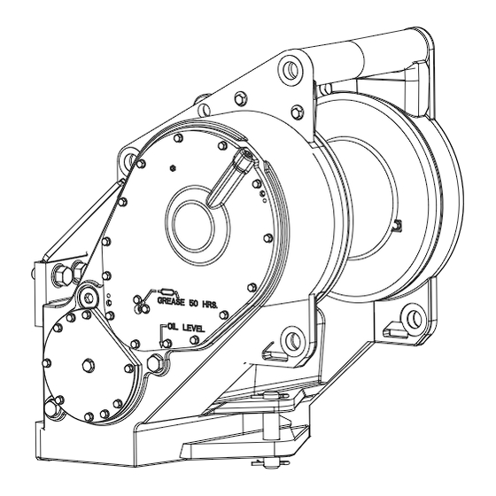
Page 6: Cross Section
Bull Gear Drum Shaft Lower Reduction Gear Group Hydraulic Cartridge Motor Group... -
Page 8: Preventative Maintenance
PREVENTATIVE MAINTENANCE A regular program of preventive maintenance for your PAC- manufacturer’s recommendations. Use the type of hydrau- CAR winch will minimize the need for emergency servicing lic oil recommended by the tractor manufacturer. and promote long product life and trouble-free service. Change the tractor hydraulic oil in accordance with the The service intervals suggested in this manual will opti- tractor manufacturer’s recommendations. - Page 9 WINCH CABLE (WIRE ROPE) Inspect the entire length of wire rope and the hook in ac- cordance with the rigging manufacturer’s recommenda- tions. MOUNTING FASTENERS Check / tighten all winch mounting fasteners to recom- mended torque after the fi rst 100-250 hours of operation, then every 1000 operating hours or six (6) months, which- ever occurs fi...
-
Page 10: Oil Recommendations
Your lubricant supplier should assure you that his product meets this specifi cation. If there is any doubt as to the suit- ability of a lubricant, contact the PACCAR Winch Service Department, providing a copy of the product specifi cations. -
Page 11: Winch Removal And Installation
WINCH REMOVAL AND INSTALLATION Hot oil can cause injury. Make certain the oil has cooled Before servicing, make sure any trapped oil pressure to a safe temperature (less than 110°F or 43°C) before in the tractor hydraulic system has been relieved. Per- servicing the winch. -
Page 12: Wire Rope Installation
WIRE ROPE INSTALLATION All winches are rated at bare drum line pull. As the cable Winch cable anchors (ferrule and ferrule pocket) are drum fi lls, the line pull will decrease (loss of leverage) while NOT designed to hold full rated load. Winch loads ap- the line speed increases (larger circumference). -
Page 13: Troubleshooting Guide
TROUBLESHOOTING The following troubleshooting section is provided as a general guide. You may also need to contact the Origi- nal Equipment Manufacturer (OEM) for additional information. If a hoist exhibits any sign of: - Erratic operation such as poor load control, load creeping down or chattering. - Unusual noise. - Page 14 TROUBLE PROBABLE CAUSE REMEDY Oil leaking from the vent plug. 1. Same as A2. A. Same as A2. 2. Motor seal may be defective as a A. Hydraulic motor case drain pres- result of high hydraulic motor case sure must not exceed 40 PSI (2.8 drain pressure or contaminated kg/cm2).
- Page 15 PROBABLE CAUSE TROUBLE REMEDY The winch will not pull the rated load. 1. The hydraulic system relief valve A. Check system relief pressure as may be set too low. The relief valve follows: may need replacement or repair. Install an accurate gauge into the tractor pump pressure port per the tractor manual.
- Page 16 PROBABLE CAUSE TROUBLE REMEDY TROUBLE “E” CONTINUED FROM Check suction line for damage. PREVIOUS PAGE Pump worn or damaged. Inspect /replace pump as needed. See tractor service manual for more in- formation. 2. Excessively worn or damaged in- A. Disassemble winch for inspection ternal winch components.
-
Page 17: Service Precautions
SERVICE PRECAUTIONS After troubleshooting the winch and its hydraulic system as covered in the “Trouble Shooting” section of this manual, and the problem is determined to be in the winch, use the following procedure to disassemble the winch as needed. •... - Page 18 Drive-away Valve Drawing The hydraulic group consists of the hydraulic motor, winch control valve, drive-away valve, and hoses and fi ttings. Ports to measure loop pressure on the drive-away valve can be accessed at the lower right winch case cover, but the winch must be removed from the tractor for most service on the hydraulic group.
-
Page 19: Winch Disassembly
WINCH DISASSEMBLY FREESPOOL GROUP DISASSEMBLY Ensure the winch oil is cool and hydraulic pressure is released before any work is done on the winch. High pressure oil and hot oil can cause death or personal injury. 1. Bleed the pressure from the tractor hydraulics by cy- cling the joystick with power on but with the tractor en- gine off. -
Page 20: Freespool Group Assembly
FREESPOOL GROUP ASSEMBLY Wash all parts in solvent before assembly. 1. Place spring (711) in drum shaft (202). Slide freespool clutch (709) onto bull gear (601). 2. Place retaining ring (712) on freespool clutch (709). In- stall compression tool in position using the two ½”-13 tapped holes in the bull gear (601). -
Page 21: Lower Reduction Gear Disassembly
LOWER REDUCTION GEAR DISASSEMBLY Remove the freespool group – refer to Freespool Group CAUTION section in this manual. The drum group must be disassembled before the bull The 1st reduction gear (605) weights 38 lbs, and 2nd gear can be removed, so disassembly of both groups is reduction gear (606) weighs 22 lbs. -
Page 22: Lower Reduction Gear Assembly
LOWER REDUCTION GEAR ASSEMBLY (Refer to drawing on p.21) 1. Pack all bearings with grease prior to installation. Use NLGI #2 EP (extreme pressure) grease with a Lithium complex base that meets or exceeds NLGI GC/LP re- quirements. 2. Install retaining ring (618) on shaft (607). Place thrust race (609) on the shaft. -
Page 23: Drum & Bull Gear Disassembly
DRUM AND BULLGEAR DISASSEMBLY The lower reduction gears must be removed before the removal of the upper bull gear or before the removal of any components in the cartridge assembly. The winch drum weighs approximately 240 lbs (109 kg). Ensure rigging for lifting or supporting the drum is properly rated. - Page 24 3. Remove socket head capscrew (206) which secures the locknut (205) in position. User a spanner wrench to remove the locknut (205). CAUTION The bull gear (601) and shaft (202) weigh approximately 125 lbs (57 kg) as a unit. Use proper lifting equipment when removing them from the winch drum.
-
Page 25: Drum & Bull Gear Assembly
DRUM AND BULLGEAR ASSEMBLY (see drawings on pg. 21 & 23) 1. Install seals (208) into winch case driving them from Install bearing (602) into bull gear (601) and install the drum area of the case until fl ush with the winch retaining ring (603) in bull gear (601). -
Page 26: Cartridge Assembly Service
CARTRIDGE ASSEMBLY UNIT REMOVAL The cartridge assembly can be removed as a unit for servicing. However, removing the cartridge assembly requires the removal of the winch from the tractor and removal of the winch motor. The individual components within the cartridge assembly can be service with the winch on the tractor. -
Page 27: Pinion Carrier Service
PINION CARRIER PINION CARRIER DISASSEMBLY ASSEMBLY Proceed to Step 4 if the complete cartridge is removed 1. Use an induction heater to heat the inner race of bear- from the winch. This procedure assumes the parts will be ing (364) and install on pinion (362). serviced with the winch on the tractor, but the same steps are followed if working on a bench. -
Page 28: Planet Carrier Service
PLANET CARRIER ASSEMBLY DISASSEMBLY 1. Place the output planet carrier on workbench with 1. Remove the planet gears by driving the roll pins into splined coupling side down. Install output thrust plate the center of the planet shafts. in center of carrier. 2. -
Page 29: Brake Cylinder Service
BRAKE CYLINDER SERVICE The Brake Cylinder is a subassembly of the Cartridge As- sembly. It can be serviced with the winch on the tractor or on a bench if the entire Cartridge Assembly is removed from the winch. The hydraulic motor must be removed to remove the entire Cartridge Assembly. - Page 30 CLEAN AND INSPECT 7. Position the brake piston (317) onto the brake retain- 1. Thoroughly clean and inspect all brake cylinder as- er and discs. Carefully align the teeth on the friction sembly parts. Check the brake piston and sealing discs (318), and then slide the motor coupling (331) surfaces on the brake cylinder for signs of scoring and into the assembled brake parts to fully align the friction...
-
Page 31: Metric Conversion Chart
METRIC CONVERSION TABLE English to Metric Metric to English LINEAR inches (in.) X 25.4 = millimeters (mm) millimeters (mm) X 0.3937 = inches (in.) feet (ft.) X 0.3048 = meters (m) meters (m) X 3.281 = feet (ft.) miles (mi.) X 1.6093 = kilometers (km) kilometers (km)
Need help?
Do you have a question about the CARCO H50VS and is the answer not in the manual?
Questions and answers