
Related Manuals for Nvidia QM9700


Summary of Contents for Nvidia QM9700
- Page 1 QM9700/QM9790 1U NDR 400Gb/s InfiniBand Switch Systems User Manual Exported on Oct/24/2022 09:50 AM...
-
Page 2: Table Of Contents
Table of Contents Introduction..................5 Speed and Switching Capabilities ..............6 Management Interfaces, PSUs and Fans ............6 Features ....................6 Certifications ..................7 Installation ..................8 System Installation and Initialization .............8 Safety Warnings ..................9 Air Flow....................9 Package Contents .................. 10 19” System Mounting Options ..............10 Tool-Less Rail Kit ................... - Page 3 RS232 (Console) ..................41 Management ..................42 USB ....................42 I²C ....................42 Reset Button ..................43 LEDs ....................43 LED Notifications................... 43 System Status LED ................44 Fan Status LED.................. 45 Power Supply Status LEDs..............45 Unit Identification LED................ 47 Port LEDs ..................
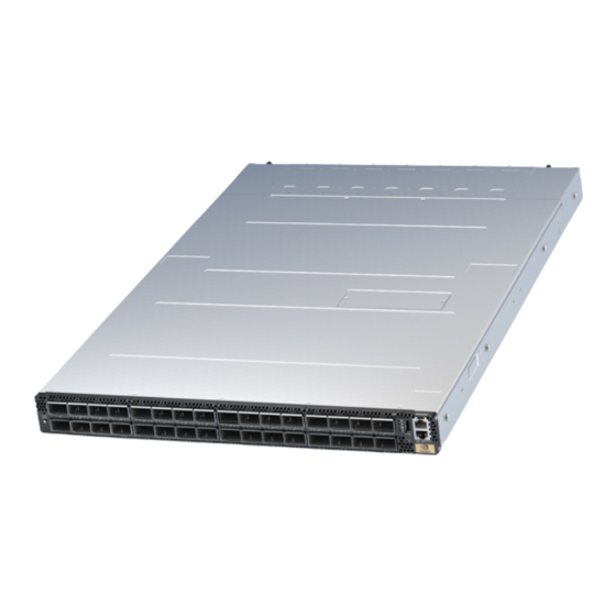
- Page 4 Relevant for Models: QM9700 and QM9790 This manual describes the installation and basic use of the NVIDIA 1U NDR InfiniBand switch systems based on the NVIDIA Quantum™-2 switch ASIC. This manual is intended for IT managers and system administrators. Ordering Information...
-
Page 5: Introduction
Supporting up to 128 ports of 200Gb/s, NVIDIA delivers the densest top-of-rack (TOR) switch available on the market. The QM9700 family of switches enables small to medium-sized deployments to scale with a two-level Fat Tree topology while reducing power, latency, and space requirements. ... -
Page 6: Speed And Switching Capabilities
QM9700 and QM9790 Rear View For additional airflow options, see Airflow. Speed and Switching Capabilities The table below describes maximum throughput and interface speed per system model. 64 NDR non-blocking ports with aggregate data throughput up to 51.2Tb/s System Model NDR 400Gb/s OSFP Interfaces... -
Page 7: Certifications
Certifications The list of certifications (such as EMC, Safety and others) per system for different regions of the world is located on the Mellanox website at http://www.mellanox.com/page/ environmental_compliance. -
Page 8: Installation
Due to thermal considerations, the switch systems must be installed in a horizontal position. do not install the systems vertically. • Unless otherwise specified, NVIDIA products are designed to work in an environmentally controlled data center with low levels of gaseous and dust (particulate) contamination. •... -
Page 9: Safety Warnings
Warnings. Note that some warnings may not apply to all models. Air Flow NVIDIA systems are offered with two air flow patterns: • Power (rear) side inlet to connector side outlet - marked with blue dots that are placed on the power inlet side. -
Page 10: Package Contents
1 – Rail kit • 4 – Power cables Type C14 to C15 • 1 - Harness: HAR000631 – Harness RS232 2M cable – DB9 to RJ-45 (only in QM9700) • 2 – Cable retainers • 32 - OSFP thermal caps ... - Page 11 Prior to the installation procedure, inspect all rail-kit components and make sure none of them is missing or damaged. If anything is missing or damaged, contact your NVIDIA representative at Networking-support@nvidia.com. The following parts are included in the tool-less rail kit (see figure below): •...
- Page 12 The following steps include illustrations that show front side (ports) installation, yet all instructions apply to all installation options. Attach the left and right system rails (A) to the switch. Attaching the System Rails (A) to the Switch Secure the assembly by gently pushing the system chassis’ pins through the slider key holes, until locking occurs...
- Page 13 Securing the System in the Switch Rails (A) Chassis' Pins in the Rails' Slots Locking them in a Fixed Position Mount both of the rack rails (B) into the rack by angularly inserting the brakes located at the rails edges into the designated slots in the rack unit, as shown in the following figure: ...
- Page 14 Inserting the Rack Rails (B) Align both rack rails (B) to sit horizontally in parallel to the rack assembly. By straightening the rails' angular position, their breaks will be caught and locked in the rack's slots. Aligning the Rack Rails (B) Angular The Breaks are Caught and Locked in the Position ...
- Page 15 Rack Rails Fully Inserted and Locked in the Rack Assembly Pull the rack rails' telescopic extensions all the way to the rack's opposite side, and insert the latches at the rails' free edges to the rack's slots. A click should be heard as the spring latches are fully inserted and locking occurs.
- Page 16 Pulling the Rails Telescopic Extensions To mount the system into the rack: At least two people are required to safely mount the system in the rack. While your installation partner is supporting the system’s weight, perform the following steps: Slide the rails installed on the system into the channels in the rack rails.
- Page 17 Sliding the System Rails (A) into the Rack Rails Tightening the Captive Screws To remove the system from the rack: Turn off the system and disconnect it from peripherals and from the electrical outlet. While your installation partner is supporting the system’s weight: Loosen the captive screws attaching the system's rails to the rack's posts. ...
- Page 18 Pressing the Spring Latches on Both Sides Remove the rails from the system. Release the metal latches and pull out the rails, so the system's pins will be removed out of the oval slots. Removing the Rails from the System Remove the rails from the rack by pressing the lock button, and pull the rails outside of the rack assembly.
-
Page 19: Cable Installation
Pressing the Lock Button to Remove the Rails from the Rack Cable Installation Power Cable and Cable Retainer In some switch models, the product's package includes cable retainers. It is highly recommended to use them in order to secure the power cables in place. When installing retainers for the PSUs of the QM97x0 switch systems, please adhere to the following instructions: ... - Page 20 Proper Condition Improper Condition It is advised to place the PSU on a flat, stable surface. While you secure the PSU in place, use two thumbs to insert the retainer's two snaps into the designated holes located near the AC inlet. Make sure that the retainer's plastic loop is facing upwards, as demonstrated in the below table.
-
Page 21: Port Cables
Fully Mated Retainer Make sure that the retainer is fully locked in place by gently attempting to pull it outwards. Open the plastic loop and route the AC cord through it. Locate the loop over the AC cord, as shown in the following table, and fasten it tightly. Proper Loop Placement ... - Page 22 To remove a cable, disengage the locks and slowly pull the connector away from the port receptacle. The LED indicator for that port will turn off when the cable is unseated. For full cabling guidelines, ask your NVIDIA representative for a copy of NVIDIA Cable Management Guidelines and FAQs Application Note.
- Page 23 "InfiniBand Switching" chapter in the latest MLNX-OS® User Manual. QM9700/QM9790 Splitting Options All OSFP ports are splittable. Each OSFP cage contains two ports of 400G, and each port can be split to two. There are no blocking requirements.
-
Page 24: Initial Power On
It may take up to five minutes to turn on the system. If the System Status LED shows amber after five minutes, unplug the system and call your NVIDIA representative for assistance. Check the frontal System Status LEDs and confirm that all of the LEDs show status lights consistent with normal operation (initially flashing, and then moving to a steady color) as shown below. -
Page 25: System Bring-Up Of Managed Systems
If no obstacles were found and the problem persists, call your NVIDIA representative for assistance. Two Power Inlets - Electric Caution Notifications: ... - Page 26 configured DHCP, you may find the explanation in Disable Dynamic Host Configuration Protocol (DHCP) sufficient. In case manual configuration is required, please refer to the instructions in Manual Host Configuration. Disable Dynamic Host Configuration Protocol (DHCP) DHCP is used for automatic retrieval of management IP addresses. If a user connects through SSH, runs the wizard and turns off DHCP, the connection is immediately terminated, as the management interface loses its IP address. In such a case, the serial connection should be used.
- Page 27 This terminal is not active input or output while booting. Boot Menu ------------------------------------------------------------------- 0: <image #1> 1: <image #2> ------------------------------------------------------------------- Use the ^ and v keys to select which entry is highlighted. Press enter to boot the selected image or to enter a password to unlock the next set of features.
- Page 28 Wizard Session Display (Example) Comments Step 2: Use DHCP on mgmt0 interface? [yes] Perform this step to obtain an IP address for the switch. (mgmt0 is the management port of the switch.) - If you wish the DHCP server to assign the IP address, type “yes”...
- Page 29 Wizard Session Display (Example) Comments Step 8: Admin password (Must be typed)? <new_password> To avoid illegal access to the machine, please type a password and then press <Enter>. Starting from the 3.8.2000 release, the user must type in the admin password upon initial configuration.
- Page 30 Wizard Session Display (Example) Comments Step 1: Hostname? [switch-1] If you wish to accept the default hostname, then press <Enter>. Otherwise, type a different hostname and press <Enter>. Step 2: Use DHCP on mgmt0 interface? [yes] Perform this step to obtain an IP address for the switch.
- Page 31 Wizard Session Display (Example) Comments You have entered the following information: The wizard displays a summary of your choices and Hostname: <switch name> then asks you to confirm the choices or to re-edit Use DHCP on mgmt0 interface: yes them. Enable IPv6: yes Enable IPv6 autoconfig (SLAAC) on mgmt0 Either press <Enter>...
- Page 32 IP Zeroconf Configuration Wizard Session Display (Example) Configuration wizard Do you want to use the wizard for initial configuration? y Step 1: Hostname? [switch-112126] Step 2: Use DHCP on mgmt0 interface? [no] Step 3: Use zeroconf on mgmt0 interface? [no] yes Step 4: Default gateway? [192.168.10.1] Step 5: Primary DNS server? Step 6: Domain name?
- Page 33 Wizard Session Display (Example) Configuration wizard Do you want to use the wizard for initial configuration? y Step 1: Hostname? [switch-mgmt1] Step 2: Use DHCP on mgmt0 interface? [yes] Step 3: Enable IPv6? [yes] Step 4: Enable IPv6 autoconfig (SLAAC) on mgmt0 interface? [no] Step 5: Enable DHCPv6 on mgmt0 interface? [yes] Step 6: Admin password (Enter to leave unchanged)? Step 7: HA Chassis IP address: [10.6.166.200]...
-
Page 34: Configuring The Switch With Ztp
<switch ip address>”. rem_mach1 > ssh -l <username> <ip address> Log into the switch (default username is admin, password admin). Read and accept the EULA when prompted. Once the following prompt appears, the system is ready to use. NVIDIA MLNX-OS Switch Management... -
Page 35: Fru Replacements
FRU Replacements Power Supply NVIDIA systems are equipped with two replaceable power supply units work in a redundant configuration. Either unit may be extracted without bringing down the system. Make sure that the power supply unit that you are NOT replacing is showing all green, for both the power supply unit and the rear System Status LEDs. -
Page 36: Fans
Remove the power supply unit. PS Unit Pulled Out To insert a power supply unit: Make sure the mating connector of the new unit is free of any dirt and/or obstacles. Do not attempt to insert a power supply unit with a power cord connected to it. Insert the power supply unit by sliding it into the opening, until a slight resistance is felt. - Page 37 Fan Module Latches To remove or replace a fan unit, gently pull out its handle while pushing the latch release with your index finger. To insert a fan unit: Make sure the mating connector of the new unit is free of any dirt and/or obstacles. Insert the fan unit by sliding it into the opening until slight resistance is felt.
-
Page 38: Software Management
Software and firmware updates are available from the NVIDIA Support website. Check that your current revision is the same one that is on the NVIDIA website. If not upgrade your software. Copy the update to a known location on a remote server within the user’s LAN. -
Page 39: Updating Firmware On Externally Managed Systems
• (Non-typical) Via the I²C port of the switch using an NVIDIA MTUSB-1 device connecting to a server's USB port on the one end and to the I²C port of the switch on the other. Firmware updates should normally be conducted in-band. The use of the MTUSB-1 device is intended for cases of debug or firmware corruption and should be conducted by NVIDIA FAEs or Support engineers, or by trained users at the customer's site. - Page 40 # flint -d <device> q# Compare the results of this command with the latest version for your system posted on https://network.nvidia.com/support/firmware/firmware-downloads/ (select the Quantum™ System page). If the current version is not the latest version, follow the directions in the MFT User manual to burn the new firmware inband.
-
Page 41: Interfaces
40/56/100/200/400 Gb/s. The system offers Class 8 (17W) OSFP112 transceivers support. Speed InfiniBand speed is auto-adjusted by the InfiniBand protocol. NVIDIA systems support QDR/FDR/EDR/ HDR/NDR InfiniBand. • FDR is an InfiniBand data rate, where each lane of a 4X port runs a bit rate of 14.0625Gb/s with 64b/66b encoding, resulting in an effective bandwidth of 56.25Gb/s. -
Page 42: Management
connect a PC to this interface and configure network parameters for remote connections. Refer to Configuring Network Attributes to view the full procedure. This interface is not found in externally managed systems. Management The Management RJ45 Ethernet ports labeled “ ” provide access for remote management. The management ports are configured with auto-negotiation capabilities by default (100MbE to 1000GbE). -
Page 43: Reset Button
NVIDIA cables supplied with the switch package can be used to connect a switch system to the server. Connecting any cable other than the NVIDIA supplied console cable may cause an I²C hang. Using uncertified cables may damage the I²C interface. Refer to the .Replacement Parts Ordering Numbers v2.4... -
Page 44: System Status Led
The LED in the red rectangle shows the system’s status. It may take up to five minutes to turn on the system. If the System Status LED shows amber after five minutes, unplug the system and call your NVIDIA representative for assistance. System Status LED Assignments LED Behavior... -
Page 45: Fan Status Led
Fan Status LED Fan Status LED - Front and Rear Sides Front Panel Description Rear Panel Both of these LEDs in the red rectangles show the fans’ status. Fan Status Front LED Assignments LED Behavior Description Action Required Solid Green All fans are up and running. - Page 46 Action Required Solid Green All PS units are connected and running normally. Flashing Green 1Hz Call your NVIDIA representative for AC present / Only 12VSB on (PSU off) or PSU assistance. in Smart-on state. Amber AC cord unplugged or AC power lost while...
-
Page 47: Unit Identification Led
LED Behavior Description Action Required Flashing Amber Power supply warning events where the Call your NVIDIA representative for power supply continues to operate; high assistance. temp, high power, high current, slow fan. No AC power to all power supplies. Call your NVIDIA representative for assistance. -
Page 48: Inventory Pull-Out Tab
Lane Select Button States State LED Status Ports LED Indication 0 (Default) LED is off 4x || 2xA LED is on 4x || 2xB The port LEDs behavior indicates the ports’ state, as follows: Port LEDs in InfiniBand System Mode LED Behavior Description Action Required Link is down. - Page 49 The images provided here are for illustration purposes only. The may not reflect the latest version of the product nor all available models.
-
Page 50: Troubleshooting
Troubleshooting Problem Symptoms Cause and Solution Indicato LEDs System Status LED is blinking Cause: MLNX-OS software did not boot properly and only firmware for more than 5 minutes is running. Solution: Connect to the system via the console port, and check the software status. -
Page 51: Specifications
Specifications QM9700 and QM9790 Technical Specifications Feature Value Mechanical Size: 1.7” (H) x 17.2” (W) x26” (D), 43.6mm (H) x 438mm (W) x 660mm (D) Mounting: 19” rack mount Weight: 1 PSU: 13.6 kg 2 PSUs: 14.8 kg Speed: 40, 56, 100, 200, 400 Gb/s per port Connector cage: ... -
Page 52: Appendixes
Ordering Part Numbers for Replacement Parts Part Number Legacy Part Part Description Number 930-9BRKT-00JM-00 MTEF-KIT-I-TL NVIDIA 19" racks ,Tool-less rail-kit for QM97xx system, Rack size 0 600-800mm 930-9BFAN-00IW-00 MTEF-FANF-L 400G 1U systems FAN MODULE W/ P2C air flow 0 930-9BFAN-00JA-00... -
Page 53: Interface Specifications
• Emergency – 130°C: In case the firmware fails to shut down the ASIC device upon crossing its Critical threshold, the device will auto-shutdown upon crossing the Emergency (130°C) threshold. Interface Specifications OSFP Pin Description Net Name PinNum Signal Description Ground TX2P Transmitter Data Non-Inverted ... -
Page 54: Rj45 To Db9 Harness Pinout
Net Name PinNum Signal Description Ground Ground RX2P Receiver Data Non-Inverted RX2N Receiver Data Inverted Ground RX4P Receiver Data Non-Inverted RX4N Receiver Data Inverted Ground RX6P Receiver Data Non-Inverted RX6N Receiver Data Inverted Ground RX8P Receiver Data Non-Inverted RX8N Receiver Data Inverted Ground INT_RSTn INT/RSTn ... -
Page 55: Disassembly And Disposal
RJ-45 Console and I²C interfaces are integrated in the same connector. Due to that, connecting any cable other than the NVIDIA supplied console cable may cause an I²C hang. Using uncertified cables may damage the I²C interface. Refer to the Replacement Parts Ordering Numbers appendix for harness details. - Page 56 Follow the instructions found at http://www.mellanox.com/page/dismantling_procedures for proper disassembly and disposal of the switch, according to the WEEE directive.
-
Page 57: Document Revision History
Document Revision History Date Revision Description July 2022 Updated OPNs in: • Ordering Information • Installation • Accessory and Replacement Parts Updated Cable Installation. February 2022 Updated Cable Installation. November 2021 Initial release... - Page 58 NVIDIA accepts no liability related to any default, damage, costs, or problem which may be based on or attributable to: (i) the use of the NVIDIA product in any manner that is contrary to this document or (ii) customer product designs.
- Page 59 Copyright © 2022 NVIDIA Corporation & affiliates. All Rights Reserved.
Need help?
Do you have a question about the QM9700 and is the answer not in the manual?
Questions and answers